Diesel Injection Pump: Faults, Replacement & Maintenance
Diesel injection pump guide for heavy trucks and buses: fault symptoms, diagnosis, replacement steps, torque and pressure values, and maintenance tips.
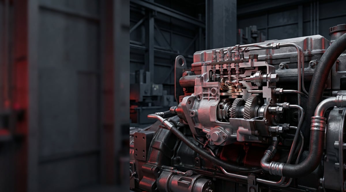
The power, the fuel economy and the exhaust smoke of a heavy commercial diesel engine all come down to a single question: is the right amount of fuel reaching the injector, at the right pressure, at the right moment? The unit that does this job is the fuel injection pump — known on the shop floor simply as the diesel pump. When this pump weakens on a tractor unit or a bus, the result is not merely "a bit of sluggishness": hard starting, power loss on climbs, black or white smoke, rough idle and rising fuel consumption follow in a chain reaction. This guide brings together, in plain field language, the operating logic of the injection pump for heavy diesel vehicles, fault diagnosis, correct replacement practice and safe technical values.
What Is an Injection (Diesel) Pump? Its Function and Operating Principle
The injection (diesel) pump is the high-pressure pump that, in a heavy commercial diesel engine, takes low-pressure fuel and raises it to high pressure, delivering the right amount of fuel with the right timing to the injectors or the common fuel rail on every operating cycle of the engine. In a diesel, ignition happens not through a spark plug but through the compression temperature in the cylinder; that is why injecting the fuel at very high pressure and with precise timing — indeed the entire combustion process — is the job of this pump. The pump is driven from the engine through a gear or coupling (drive connection) and rotates in sync with the crankshaft. In heavy diesels this unit works on the same principle as Bosch-type in-line, rotary and common-rail pumps and their equivalents; the VADEN Fuel System product group covers the service parts around this assembly — the injection pump overflow valve, the drive coupling, the pump pipe and the repair kit, along with the feed pump, the hand pump, the injector line pipes and the fuel filter parts.
An injection pump is not a single part but a subsystem that works together. Its main components are:
- Pump housing and pressure elements: The piston/plunger (in in-line and CP types) or rotor group (in rotary types) that raises the fuel to high pressure.
- Feed (transfer) pump: The low-pressure stage that supplies the fuel coming from the tank to the high-pressure section under pre-pressure; in many types it is located inside the pump.
- Overflow valve: The valve that keeps the pressure in the return line and the feed gallery pressure at a set value and sends the excess fuel back to the tank.
- Timing mechanism: The mechanism that sets the moment of injection according to speed and load; in mechanical types an advance device manages it, in electronic types the control unit does.
- Drive coupling / gear: The connection that links the pump to the engine in sync and transmits the rotational motion.
In-line, rotary and common-rail: the three main types
In in-line pumps (e.g. the equivalent of the Bosch P/PE family) there is a separate plunger element for each cylinder; they are common in large heavy diesels that demand high pressure and durability. In rotary pumps (VE-type equivalent) a single distributor element feeds all the cylinders in turn; they are more compact and suitable for the medium-power class. The common-rail high-pressure pump (CP-type equivalent), on the other hand, pressurizes the fuel to very high pressure into a shared line (rail); the amount and moment of injection are determined not by the pump but by electronically controlled injectors. The vast majority of modern EURO 5/6 heavy commercial vehicles use common-rail systems.
Why is the role of the overflow valve critical?
The overflow valve is a part most users overlook, yet it directly determines the stability of the system. Its job is to keep the gallery pressure constant by returning the excess fuel in the feed circuit to the tank in a controlled manner, and, through this flow, to provide both cooling and air bleeding by continuously passing fuel through the pump. When the overflow valve weakens, the gallery pressure drops, and power loss and air ingress (air bubbles in the fuel line) appear during hot running; when the valve stays clogged, the return is restricted and the pressure balance is disrupted.
OE-equivalent types and vehicle-engine matching
What determines the correct pump choice is the engine family, the system type (in-line/rotary/common-rail), the drive connection and the required flow/pressure. The table below is a guiding match for common heavy commercial platforms.
| Vehicle family (example) | Engine family | Typical system / pump type | Tendency |
|---|---|---|---|
| Mercedes-Benz Actros / Antos | OM 470 / OM 471 | Common-rail (CP-type equivalent) or PLD unit injector | Very high pressure, electronic |
| Volvo FH / FM, Renault T | D11 / D13 | Unit injector / common-rail (equivalent) | High pressure, electronic |
| Scania R / S | DC13 / DC16 | PDE / XPI common-rail equivalent | High pressure (shift to XPI in the new generation) |
| MAN TGX / TGS | D26 (D2676) | Common-rail (CP-type equivalent) | High pressure, electronic |
| Older-generation truck / construction machinery | Mechanical diesel | In-line (P/PE-type equivalent) or rotary (VE-type equivalent) | Mechanical, medium pressure |
| Bus / midibus (mechanical generation) | Various | In-line or rotary equivalent | Mechanical timing |
Fault Symptoms and Diagnosis
Most injection pump faults fall under three main headings: insufficient fuel pressure/flow, air ingress and supply problems, and poor combustion quality (smoke, power loss). The critical point is this: the same symptom (for example hard starting or black smoke) can originate from the pump, the injector, the fuel filter, or a simple air leak alike. That is why diagnosis must be done by isolating the system before removing the expensive pump.
| Symptom | Possible Cause | Check / Verification |
|---|---|---|
| Engine starts hard or does not start at all | Air in the fuel line, clogged fuel filter, weak feed pump, overflow valve fault | First bleed the air with the hand pump (priming); check the filter change and the feed pressure; read the rail/gallery pressure |
| Marked power loss on climbs / under load | Low high-pressure, worn plunger/element, low gallery pressure, restricted fuel flow | Measure the fuel feed pressure and (on common-rail) the rail pressure together with load; rule out filter and intake-line restriction |
| Black smoke from the exhaust | Excessive/mistimed fuel, poor spray pattern, incorrect timing, injector fault | Check the injectors and the timing; rule out the injector and the air filter before blaming the pump |
| White/bluish smoke from the exhaust, delayed ignition on starting | Insufficient pressure or late timing, water in the fuel, fuel not burning when cold | Check the timing and the feed pressure; inspect the water separator for water/dirt in the fuel |
| Rough idle, engine shaking / stalling | Unbalanced supply between cylinders, air ingress, overflow valve/regulator instability | Observe whether there are air bubbles in the return line; monitor the stability of the gallery/rail pressure |
| Increased fuel consumption, excessive fuel in the return | Worn element, leaking valve, overflow/pressure regulator out of adjustment | Measure the return flow; excessive return points to internal leakage |
| Fuel leak / wetness around the pump | Worn seal/O-ring, loose union, damaged seal | Inspect the connections and the seal/gasket areas for leaks on a clean surface |
Distinguishing the air ingress (air in the fuel line) symptom
The diesel fuel system will not tolerate air; even the smallest intake leak on the feed side draws air in and the pump starts to compress air instead of fuel. If hard starting, stalling during running and idle roughness are seen together, first look for an air leak: a loose fuel filter head, a worn O-ring, a cracked fuel line or an emptied water separator are the most frequent culprits. Seeing bubbles in the fuel circulating in a transparent piece of line is clear proof. Before blaming the pump, fully bleed the air from the system with the hand pump (priming) and see whether the problem persists.
Distinguishing the insufficient power / pressure symptom
Power loss under load is the first warning. But before condemning the pump, rule out the supply chain: a clogged fuel filter, a restricted intake line or a weak feed pump gives the same symptom by preventing enough fuel from reaching the high-pressure section. If the feed pressure and (on a common-rail system) the rail pressure are normal and the filter is clean, the power loss most likely originates from a worn pressure element or internal leakage.
Distinguishing the water/dirt-in-fuel damage symptom
Injection pumps work with micron-level tolerances and are lubricated by the fuel; that is why water and dirt in the fuel are their greatest enemies. Water breaks down the lubricating film, causing corrosion and wear on the plunger and valve surfaces, while dirt causes scoring and clogging. If continuous water accumulation in the water separator, early clogging in the filter and rust/wear on the internal pump surfaces are seen together, the root cause is a lack of clean fuel; merely replacing the pump will, without eliminating the source, ruin the new pump in a short time as well.
Further reading
For a plain-language technical overview of this subject, see the reference article on Wikipedia. Always confirm specific figures and procedures against the vehicle manufacturer service data.
Replacement / Installation Steps
The steps below are a general sequence for heavy diesels (truck/tractor unit/bus); always rely on the timing, torque and procedure values in the service manual of the vehicle and the pump. Injection pump replacement is a job that is sensitive in terms of timing and cleanliness; if you are not sure, work with an authorized diesel service.
- Secure the vehicle: Park on level ground, chock it, switch off the ignition, disconnect the negative battery terminal. On a common-rail system, follow the manufacturer's waiting/relief procedure so the high pressure is discharged.
- Set the engine to timing (on mechanical/gear drive): Identify the timing marks (crankshaft and pump) and bring cylinder 1 to TDC or the manufacturer's reference position. Do not remove the drive without recording this position — wrong timing will not let the engine run or will damage it.
- Mark the fuel lines and connections: Photograph and label the feed, return (overflow), high-pressure pipes, electrical connectors and, if present, the timing sensors. Never reuse high-pressure pipes by re-bending them.
- Remove the lines and cap the openings: Disconnect all fuel lines; cap every open opening (pump, pipe, injector) with a clean plug/cover. Even the smallest dirt entering the system puts the new pump at risk.
- Release the drive connection: Undo the coupling/gear nut using the manufacturer's method. On gear drive, note the timing marks and the gear backlash; use a suitable puller, do not force it with impact.
- Remove the old pump: Undo the mounting bolts and lower the pump while supporting it. The pump is heavy and full of fuel; be prepared for tipping and spillage.
- Clean the mounting surface and the circuit: Clean the old gasket/O-ring residue on the flange surface. Take this opportunity to renew the fuel filter and the water separator; in faults caused by dirty fuel, also consider cleaning the tank and the lines.
- Fit the new pump and the new gasket: Always use a new gasket/O-ring. Seat the pump in place and tighten the mounting bolts to the manufacturer's torque progressively and in a crosswise sequence (see the "Technical Values" section for typical ranges).
- Set the timing: On gear/coupling drive, align the timing marks exactly; on a mechanical pump, set the injection advance/static timing specified by the manufacturer. On an electronic system, perform adaptation/calibration with a diagnostic device if required.
- Connect the high-pressure and low-pressure lines: Connect the high-pressure pipes with the correct torque, without strain. Fit the feed and return (overflow) lines in the correct direction; make sure the overflow valve and the return line are open.
- Bleed the air and do the first start: Fully bleed the air from the system with the hand pump (priming); if necessary, purge through the bleed screw until clean fuel comes out. Start the engine, check for fuel leaks at all connections, and observe the idle, the smoke and the gallery/rail pressure.
Points to Watch (Common Mistakes)
- The "smoke/power loss = pump is finished" fallacy: The same symptom also comes from the injector, the fuel filter, the air filter or an air leak. Rule out the supply chain and the injectors before replacing the expensive pump.
- Starting without fully bleeding the air: Air remaining in the system leads to hard starting and stalling; do the priming with the hand pump completely, and make sure there are no bubbles left in the return line.
- Dismantling without recording the timing: On mechanical/gear drive, opening the drive without noting the timing marks results in wrong advance on assembly and a no-run condition.
- Ignoring the dirty-fuel source: If there is water/dirt damage, replacing only the pump is not enough; without renewing the filter, the water separator and, if necessary, cleaning the tank/lines, the new pump will also fail.
- Reusing/re-bending high-pressure pipes: High-pressure pipes and sealing washers that have been tightened once will leak when re-bent; renew them where the manufacturer recommends.
- Neglecting the overflow/return line: A clogged or wrongly connected return line disrupts the gallery pressure and leads to power loss and instability; check the overflow valve and the return.
Technical Values and Check Points
The values below are general/safe references for common heavy commercial vehicle diesel fuel systems. Critical values such as pressure, timing and torque vary greatly according to the vehicle, engine and pump model; for the exact figure, always rely on the relevant service manual. In particular, common-rail pressures and timing angles are engine-specific.
| Parameter | Typical / Safe Reference | Note |
|---|---|---|
| Feed (low-pressure) line pressure | ~ a few bar (e.g. the 3–6 bar band) | Varies by system; sensitive to feed pump and filter restriction |
| In-line/rotary pump injection pressure | ~ order of a few hundred bar | Depends on the type and the injector opening pressure; model-specific |
| Common-rail operating pressure | ~ order of 1000–2500+ bar | Depends on EURO class and engine; very high — safety-critical |
| Overflow / gallery pressure | Fixed value set by the manufacturer | The overflow valve maintains this pressure; if low, power loss/air ingress |
| Fuel temperature (return) | Should not rise excessively | High return temperature may be a sign of internal leakage/wear |
| Water content in the fuel | As low as possible; the water separator should be drained regularly | Water is the most destructive factor for the pump |
The pressure orders above are only intended to give an idea of magnitude; the actual values differ considerably according to the engine family and the emission class. The emission and performance requirements of diesel injection systems are defined in the EU within the framework of EURO 5/6 (e.g. (EC) 595/2009 and the related implementing regulations); the pump and injection settings are calibrated by the manufacturer to comply with these requirements. Regional regulations and vehicle manufacturer values always take priority.
Typical mounting torque and tightening sequence
The torque of the pump mounting bolts and the drive nut varies according to the bolt size, its grade (8.8/10.9) and the design. The values below are only a general reference; for the exact torque and tightening sequence, be sure to use the vehicle/pump manual. For high-pressure pipe unions, the special torque given by the manufacturer is mandatory.
| Connection (size / grade) | Typical dry torque range | Note |
|---|---|---|
| M8 / 8.8 (flange bolt) | ~22–25 Nm | General reference |
| M10 / 8.8 (flange bolt) | ~43–48 Nm | General reference |
| M10 / 10.9 | ~60–65 Nm | High-strength bolt |
| M12 / 8.8 | ~75–85 Nm | General reference |
| High-pressure pipe union | Model-specific (manual value) | Over-tightening cracks the pipe/union, under-tightening leaks |
Quick field check points
- Drain the water separator regularly; observe the accumulation of water/dirt in the fluid that comes out — chronic water means an early death for the pump.
- Comply with the fuel filter change interval; an early-clogging filter is a sign of dirty fuel or algae/sludge.
- Observe the smoke at idle and under load: black smoke tends toward excessive/mistimed fuel, white/blue smoke toward insufficient pressure or late timing.
- Check whether there are air bubbles in the return (overflow) line; a bubble points to an air leak on the intake side.
- Scan the pump and line connections for leaks on a clean surface; even the smallest wetness is a developing leak.
Maintenance and Service Life
The service life of the injection pump depends largely on a single thing: the cleanliness of the fuel. Water and dirt are the two fundamental enemies that wear the micron-tolerance surfaces and break down the lubricating film. When timely filter maintenance and preserving the correct timing are added to this, the pump becomes a very long-lived unit. A routine that keeps preventive maintenance simple extends the life of both the pump and the injector and supply system behind it.
- Daily / before the trip: Drain the water separator, do a visual fuel-leak check, observe the smoke and idle at the first start. Use quality, clean fuel.
- At periodic services: Renew the fuel filter and the water separator element at the manufacturer's interval, assess the feed pressure, scan the lines and unions for leaks.
- Fuel quality: Avoid non-standard, watery or dirty fuel; during long standstills, water condensation and microbial sludge can form in the tank — pay attention to tank hygiene.
- Timing and adjustment: Verify that the timing/advance adjustment is preserved in a mechanical system and that there is no fault record in the diagnostic device in an electronic system.
- Overflow valve and return circuit: If there is power loss or instability, check the overflow valve and the return line; the failure of a cheap part can get the expensive pump blamed.
If worn element, leaking valve and permanent power loss/excessive return due to internal leakage are seen together, it is time for the pump to be overhauled or replaced. Because injection pumps require calibration on special test benches, overhaul is a job for specialists; in many heavy commercial applications, replacing the complete calibrated unit is a more reliable solution with a more predictable total cost. In this case, renewing the fuel filter, the water separator and, where necessary, the overflow valve together with the repair kit prevents fault recurrence and markedly extends the service life. The supply system in front of the pump and the injectors behind it are parts of the same chain; for a healthy result, assess these components as a whole.
Choosing the Right Injection Pump and the VADEN Solution
After correct diagnosis, clean fuel and a meticulous installation, what is decisive is that the part you fit meets the tolerances and durability of the OE-type design. The VADEN Injection (Diesel) Pump product group — the overflow valve, the drive coupling, the pump pipe and the repair kits — covers the service parts of Bosch-type in-line, rotary and common-rail pump assemblies in heavy diesel trucks, tractor units and buses, and has been developed to meet the safe technical values and field expectations in this guide; you need only select the part suited to your requirement, together with the vehicle and engine match, assessing it as a whole with the VADEN Fuel System product group — the feed pump, the hand pump, the injector line pipes and the fuel filter parts.
Shop this part: Injector Pump
Related categories: Injector Pump · Overflow Valve · Coupling · Pipe · Repair Kit
Related technical guides: Fuel Filter & Water Separator: Faults, Change and Care Guide · Feed Pump & Hand Primer: Faults, Replacement, Maintenance · Diesel Injection Line & Fuel Pipe: Faults, Repair, Maintenance
Application and compatibility: Vehicle compatibility catalogue · Engine compatibility catalogue
Vehicles and engines mentioned in this guide: MAN D2676 · Volvo D13 · Volvo D11 · Volvo FM · Volvo FH · Mercedes-Benz Antos · Mercedes-Benz OM471 · MAN TGS I (2007-2020)
Main guide: What Is a Fuel Injector? How to Recognize Injector Failure Symptoms
Tags
Frequently Asked Questions
- What are the most obvious symptoms of an injection (diesel) pump fault?
- The most common are hard starting or no starting at all, power loss under load, black or white smoke from the exhaust, rough idle, increased fuel consumption and a fuel leak around the pump. However, these symptoms also overlap with the injector, the fuel filter and an air leak; for a definite decision, the system must be tested by isolating it.
- Is the pump always the reason the engine starts hard?
- No. One of the most frequent culprits is air in the fuel line — a loose filter head, a worn O-ring or a cracked line draws air in. A clogged fuel filter and a weak feed pump give a similar symptom too. Before blaming the pump, fully bleed the air from the system with the hand pump and check the filter/feed side.
- Does water mixing into the fuel damage the pump?
- Yes, and it is the most destructive factor. Water breaks down the fuel's lubricating film, causing corrosion and wear on the plunger and valve surfaces. Draining the water separator regularly and changing the fuel filter on time is the most effective way to protect the pump. If there is water damage, replacing only the pump is not enough; if the source is not eliminated, the new pump will fail too.
- What does the overflow valve do, and what does its failure cause?
- The overflow valve keeps the gallery pressure constant by returning the excess fuel in the feed circuit to the tank, and cools and bleeds the pump through continuous fuel flow. When it weakens, the gallery pressure drops; power loss and air ingress appear during hot running. When it stays clogged, the return is restricted and the pressure balance is disrupted. It is a cheap part, but its failure can get the expensive pump blamed.
- Does black smoke come from the pump or the injector?
- It can be either. Black smoke is generally excessive or mistimed fuel and a poor spray pattern; frequent causes are a faulty injector, late/early timing and a clogged air filter. Before blaming the pump, the injectors and the air filter should be ruled out and the timing checked.
- What is the difference between in-line, rotary and common-rail pumps?
- In an in-line pump there is a separate element for each cylinder; it is common in large, durable heavy diesels. In a rotary (VE) pump a single distributor element feeds all the cylinders; it is more compact. In a common-rail system the high-pressure pump pressurizes the fuel into a shared line and electronic injectors manage the injection; it is the standard of modern EURO 5/6 vehicles. To find the correct equivalent, it is essential to know the type of your system.
- Why does the engine start hard after fitting a new pump?
- The most common reason is that the air has not been fully bled from the system; do the priming completely with the hand pump. The second frequent reason is wrong timing — on gear/coupling drive the marks must be aligned exactly, and on a mechanical pump the advance must be set correctly. In addition, leaks at the high-pressure connections and a calibration not performed on an electronic system cause a similar problem.
- Should the pump be overhauled or replaced completely?
- The decision depends on the degree of wear and the cost. Because injection pumps require calibration on a special test bench, overhaul is a job for specialists. With heavy wear, replacing the complete calibrated unit is generally more reliable and its total cost more predictable; when renewed together with the filter, the water separator and, if necessary, the overflow valve/repair kit, it gives the longest service life.
- Do I really have to cap the open line openings while removing the pump?
- Yes. The injection pump and the injectors are micron-tolerance units, so dust, sand or fiber entering during dismantling ruins the new pump and the injectors in a short time. Cap every opening you disconnect, pump, pipe and injector alike, with a clean plug or cover immediately, work with clean gloves on a clean bench, and rinse the lines with clean fuel rather than compressed air. Clean old gasket residue off the flange too.
- How should I tighten the pump mounting bolts?
- Not in one go. Tighten progressively, for example to 50% and then to 100%, in a crosswise sequence, so the flange surface seats evenly and seals. The torque figure itself depends on bolt size, grade (8.8/10.9) and design, so take the exact value from the vehicle and pump manual. On a gear-driven pump also verify the gear backlash and the timing marks, and connect the high-pressure pipes without strain.
Related Articles

Fuel Water Separator Filter: Symptoms, Replacement & Care
Truck fuel water separator filter and housing: how it works, water sensor, drain valve, heater, fault symptoms, replacement, bleeding and maintenance.
Solenoid Coil: Faults, Testing, Replacement and Maintenance
Understand how a solenoid coil works, spot open or shorted windings with a multimeter, replace it correctly and extend its service life on trucks.
Diesel Injection Line & Fuel Pipe: Faults, Repair, Maintenance
Heavy truck injection line and fuel pipe guide: high-pressure vs supply line, leak and air ingress diagnosis, torque sequence, replacement and maintenance.


