Truck Retarder: Faults, Replacement & Maintenance Guide
Complete VADEN guide to heavy truck retarders: how hydraulic and electromagnetic types work, fault diagnosis, replacement steps, torque values and maintenance.
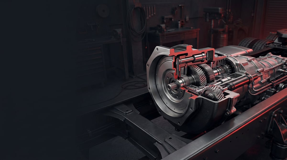
On a long downhill descent, a heavy commercial vehicle driver's greatest ally is not the service brake but the retarder. When a loaded tractor unit or coach tries to hold a gradient of tens of kilometres using only pads and discs, disc temperature climbs rapidly, the pads "fade" (lose their grip), and stopping distance grows dangerously long. This is exactly where the retarder steps in: without touching a wearing part, it converts the vehicle's kinetic energy into heat to deliver continuous, safe deceleration. This guide brings together the operating logic, fault diagnosis, correct replacement practice, and field inspection values of the retarder for heavy diesel trucks, tractor units, and buses.
What Is a Retarder (Transmission Slower / Auxiliary Brake)? Its Purpose and Operating Principle
A retarder is a wear-free auxiliary braking system on a heavy commercial vehicle that slows the vehicle by converting its kinetic energy into heat without using friction brake pads. It assists the service brake (pad + disc/drum) rather than replacing it: it engages especially during long descents and situations requiring continuous deceleration, keeping the service brake cool and at full performance. The retarder usually draws its drive from the transmission output or from a unit integrated into the propshaft; it is controlled by a stalk lever on the column with selectable stages, or by the initial movement of the brake pedal (pedal integration).
Because the retarder "takes back" part of the energy that moves the vehicle and dissipates it as heat, safely removing this heat is the heart of the system. Regardless of type, the main components work on the following logic:
- Rotor: The rotating element that takes rotational motion from the drive shaft (transmission output/propshaft) and where the deceleration force is generated.
- Stator / coil assembly: The fixed element that creates resistance against the rotor; a vaned stator in the hydraulic type, electromagnet coils in the electromagnetic type.
- Control unit: The electronic/pneumatic control that receives the stalk-lever/pedal signal and adjusts the deceleration intensity; it communicates with ABS/EBS.
- Heat-dissipation path: An oil-to-water heat exchanger and the vehicle cooling circuit in the hydraulic type; air-cooled rotor discs in the electromagnetic type.
How does a hydraulic (Voith-type) retarder work?
In a hydraulic retarder, a rotor and a stator sit opposite each other inside an oil-filled housing. When deceleration is requested, the housing is filled with oil at a control pressure; the rapidly spinning rotor flings the oil towards the stator, the stator vanes push the oil back, and this "oil resistance" brakes the drive shaft. Because there is no sliding solid surface, there is no mechanical wear; the resulting energy appears as heating of the oil and is transferred via a heat exchanger to the engine coolant and rejected through the radiator. The deceleration intensity is adjusted in stages by the amount of oil filled into the housing. This type is common in heavy tractor units and coaches that require high, continuous deceleration power.
How does an electromagnetic (Telma/ZF-type) retarder work?
An electromagnetic retarder has one or two rotor discs attached to the drive shaft, with electromagnet coils held stationary between them. When current is applied to the coils, the magnetic field induces eddy currents in the spinning rotor discs; these currents produce a counter-force that brakes the disc, and the energy is rejected as heating of the discs. The discs are cooled by airflow, so no separate liquid cooling circuit is needed. Deceleration is adjusted by the number of coil stages engaged. Thanks to its compact design and ease of maintenance, it is often preferred in city buses and medium-duty applications.
What is the difference between a retarder, an exhaust brake, and an engine brake (Jake)?
These three systems are often confused but work differently. An exhaust brake creates back-pressure against the engine by closing a butterfly valve in the exhaust line; it is simple and cheap but limited in power. An engine brake (Jake / compression brake) changes the valve timing in the cylinders and releases the compressed air at top dead centre, using the engine like an air compressor to give powerful, loud deceleration. A retarder, on the other hand, works independently of the engine via the transmission/propshaft; it offers quiet, staged, and very high sustained deceleration power. In practice, on modern heavy vehicles these systems are used together, coordinated by the EBS.
| Feature | Hydraulic retarder (Voith type) | Electromagnetic retarder (Telma/ZF type) |
|---|---|---|
| Operating principle | Rotor–stator, kinetic resistance via oil | Rotor disc + coil, eddy current |
| Cooling | Oil - water heat exchanger - vehicle radiator | Via air over the rotor discs |
| Deceleration power tendency | Very high, ideal for continuous descents | High; effect drops at low speed |
| Typical mounting | Integrated into transmission output (primary/secondary) | Separate unit on the propshaft |
| Weight / volume | Relatively compact, integrated with the transmission | Can be heavy due to rotor mass |
| Typical use | Heavy tractor unit, long-haul coach | City bus, distribution/medium-duty |
Fault Symptoms and Diagnosis
Most retarder faults fall under three main headings: weak/insufficient deceleration, stages not working, and overheating. The critical point is this: the same symptom (for example, "the retarder isn't holding") can originate from the solenoid/control valve, from the electronic control, and — in the hydraulic type — from the oil/cooling side. That is why diagnosis must be carried out by isolating the electrical/pneumatic control and the cooling before removing the unit.
| Symptom | Possible Cause | Check / Verification |
|---|---|---|
| Retarder does not decelerate at all / holds very weakly | Solenoid/control valve fault, power supply/fuse, no oil filling in the hydraulic type, no coil supply in the electromagnetic type | Read the fault codes (EBS/retarder ECU); measure the supply voltage and the solenoid signal; check the control pressure in the hydraulic type |
| Some stages work, others do not | A single solenoid/coil group faulty, stalk-lever/sensor error, wiring/connector contact | Measure the current/pressure draw at each stage separately; monitor the stalk-lever signal with an oscilloscope/scan tool |
| In the hydraulic type, oil temperature rises very high, warning illuminates | Heat exchanger blockage, low coolant/air lock, oil level/quality, continuous use of the maximum stage | Check the cooling circuit and the heat exchanger; inspect the oil level and colour; read the temperature sensor value |
| Deceleration starts but disappears after a few seconds | Protection (derating) active due to overheating, oil leak, insufficient cooling | Confirm the temperature-related power-limiting code; look for cooling performance and oil leaks |
| In the electromagnetic type, vibration / knocking with weak holding | Rotor–coil air gap incorrect, loose mounting, rotor disc deformation | Measure the air gap with a feeler gauge; check the mounting bolts and bearing play |
| Retarder stays engaged / a constant braking feel while driving | Solenoid/valve sticking on closing, control signal not cutting off, return spring/mechanism fault | Confirm that the control signal resets; remove the valve and check for sticking/contamination |
| Retarder warning/fault lamp on the dashboard | Sensor (temperature/speed) fault, ECU communication error, supply problem | Read the fault code with a scan tool; measure the CAN/EBS communication and sensor resistance |
Distinguishing the weak-deceleration symptom
"The retarder doesn't hold like it used to" is the most common complaint, but on its own it does not condemn the unit. First verify the control: is the stalk-lever/pedal signal reaching the ECU correctly, and is the solenoid/valve being energised at that stage? In the hydraulic type, oil may be filling the housing but temperature protection may be limiting the power; in the electromagnetic type, a coil group may have dropped out and reduced the total power. In a road test, check in a controlled manner whether the expected deceleration is obtained at each stage.
Distinguishing the stage-not-working symptom
Some stages working while others do not almost always points to the control side: a single solenoid/coil group not being supplied, wear on the stalk-lever contact, or oxidation at the connector. This calls for an electrical diagnosis rather than a mechanical/hydraulic fault; measuring the current draw of each stage separately quickly narrows down the culprit.
Distinguishing the overheating symptom (especially hydraulic)
In a hydraulic retarder, rising oil temperature and the subsequent power limiting (derating) is most often a problem of the cooling path rather than the unit: a blocked/dirty heat exchanger, low coolant, an air lock in the system, or saturated/old oil. The driver continuously descending at maximum stage can also make a normal protective response look like a "fault". Read the temperature sensor value and separate genuine overheating from a sensor/communication error.
Further reading
For a plain-language technical overview of this subject, see the reference article on Wikipedia. Always confirm specific figures and procedures against the vehicle manufacturer service data.
Replacement / Installation Steps
The steps below are a general sequence for heavy diesel (truck/tractor/bus); always base your work on the torque and procedure values in the service manual of the vehicle, transmission, and retarder.
- Secure the vehicle: Stop on level ground, chock the wheels, switch off the engine, and apply the parking brake. Disconnect the battery negative terminal to disable the electric control; wait for the system to cool.
- Document the connections: Photograph and label the electrical connectors, the solenoid/control-valve lines, the air/pneumatic lines, and — in the hydraulic type — the coolant and oil lines. Mark the propshaft flange position (for balance).
- Drain the fluids: In the hydraulic retarder, fully drain the oil into a suitable container; drain the unit portion of the cooling circuit according to the rules. Collect the fluids in accordance with environmental regulations.
- Disconnect the electrical and pneumatic connections: Disconnect the control connectors, solenoid/valve connections, and air lines. Cap the open ends to prevent dirt/moisture ingress.
- Release the drive/propshaft connection: Remove the propshaft flange or the transmission output connection according to its markings. In separate-unit electromagnetic types, carefully disconnect the rotor from the shaft.
- Support and remove the unit: Support the retarder unit with a suitable lift/transmission jack and remove the mounting bolts. Retarder units are heavy; never attempt to carry them by hand — use certified lifting.
- Inspect the mounting surface and the cooling path: Clean old gasket residue off the flange surface. In the hydraulic type, always check the heat exchanger and lines for blockage/deposits; a dirty heat exchanger will cause overheating even on the new unit.
- Fit the new unit and new gaskets/O-rings: Always use new gaskets and sealing elements. Seat the unit and tighten the mounting bolts to the manufacturer's torque in stages and in a cross sequence (see the "Technical Values" section for typical ranges).
- Adjust the air gap in the electromagnetic type: Set the air gap between the rotor and the coil to the manufacturer's value with a feeler gauge. An incorrect gap causes both weak holding and overheating.
- Reconnect the lines and fluids: Correctly connect the electrical, solenoid/valve, air, and cooling/oil lines. In the hydraulic type, fill with the correct grade and quantity of oil; fill the cooling circuit and bleed the air lock.
- First start-up and function test: Reconnect the battery and clear the fault codes. Start the engine; check all connections for leaks (oil/water/air). In a controlled road test, verify the deceleration of each stage and the temperature behaviour.
Points to Watch (Common Mistakes)
- The "not holding = unit is finished" fallacy: The most common cause of weak deceleration is the solenoid/control valve or the electrical supply. Before replacing the main unit, verify the control and the fault codes; most cases are solved with a repair kit or a valve.
- Fitting without measuring the air gap: In the electromagnetic type, an incorrect air gap causes weak holding and overheating even if the unit is sound. Setting it to the manufacturer's value with a feeler gauge is essential.
- Wrong oil grade/level (hydraulic): Oil other than that specified by the retarder manufacturer, or an incorrect level, degrades deceleration power and cooling. Always use the approved specification.
- Skipping the propshaft/transmission balance mark: Removing the flange without marking it leads to vibration and loss of bearing life on reassembly.
- Ignoring EBS/ABS integration: The retarder is backed off by the EBS during wheel lock-up. If the control/communication is not connected correctly, the safety function can be disabled; always perform a fault-code and function test after installation.
- Failing to fill the coolant without air: In the hydraulic type, an air lock prevents heat rejection and causes continuous overheating. Always bleed the air when filling.
Technical Values and Inspection Points
The values below are general/safe references for common heavy commercial vehicle retarder systems. Critical values such as torque, air gap, and temperature vary by vehicle, transmission, and retarder model; for exact figures, always base your work on the relevant service manual.
| Parameter | Typical / Safe Reference | Note |
|---|---|---|
| Hydraulic retarder oil operating temperature | Normal range; above ~140–150 °C critical | Varies by model; power limiting (derating) engages when exceeded |
| Deceleration power tendency (heavy tractor) | At a level that noticeably reduces the load on the service brake | Depends on stage/speed; the electromagnetic effect drops at low speed |
| Electromagnetic rotor–coil air gap | ~1.0–1.5 mm typical range | Exact value manufacturer-specific; measured with a feeler gauge |
| Solenoid/coil supply voltage | Within vehicle system tolerance (typically 24 V) | Low voltage causes weak holding |
| Coolant level/condition (hydraulic) | Full and air-free, clean | Critical for heat exchanger performance |
| Retarder oil (hydraulic) | Manufacturer-approved grade and level | Wrong oil degrades cooling and power |
As part of the vehicle's braking system, the retarder is subject to type approval; in the EU, heavy vehicle braking and endurance brake requirements are defined within the framework of ECE R13 / (EU) 2015/68, and certain vehicle classes are expected to have an endurance brake (a retarder/engine-brake combination) able to hold speed constant on long descents without using the service brake. The temperature and air-gap values above are consistent with the common ranges in the service bulletins of Voith, ZF, and Telma-type units. Regional regulations and vehicle manufacturer values always take precedence.
Typical mounting torque and tightening sequence
The torque of the retarder and flange mounting bolts varies by bolt size, class (8.8/10.9), and joint design. The values below are for general reference only; for exact torque and tightening sequence, always use the vehicle/transmission/retarder manual.
| Bolt (size / class) | Typical dry torque range | Note |
|---|---|---|
| M10 / 8.8 | ~43–48 Nm | General reference |
| M10 / 10.9 | ~60–65 Nm | High-strength bolt |
| M12 / 8.8 | ~75–85 Nm | General reference |
| M12 / 10.9 | ~105–115 Nm | High-strength bolt |
| M14 / 10.9 (flange/propshaft) | ~170–190 Nm | Varies by joint design |
Quick field inspection points
- In a controlled road/descent test, check whether each stage delivers the expected deceleration; if there is no difference between stages, suspect the control.
- In the hydraulic type, monitor the oil temperature from the gauge/scan tool; if it rises quickly and continuously on a long descent, check the cooling path.
- In the electromagnetic type, if there is vibration or "knocking" holding, check the air gap and the mounting bolts.
- Visually scan the connections for oil/water/air leaks and the connectors for oxidation/looseness.
- During installation and service, always read the retarder/EBS fault codes with a scan tool and record the function test.
Maintenance and Service Life
Retarder life depends largely on two things: clean and effective heat rejection (cooling), and a healthy control/electrical side. Because it operates without wear, its mechanical maintenance is relatively low; however, oil and cooling in the hydraulic type, and the air gap and connections in the electromagnetic type, must be monitored regularly. A simple, regular routine extends the life of both the unit and the service brake (pads/discs).
- Before a trip / daily: Observe the retarder function and the warning lamp; in the hydraulic type, check the coolant and for leaks. Before a descent, confirm that the retarder engages.
- At periodic service: In the hydraulic type, change the retarder oil and, if necessary, its filter at the manufacturer's interval; check the heat exchanger and lines for blockage/deposits. In the electromagnetic type, measure the air gap and inspect the connections and rotor condition.
- Electrical/control: Scan the connectors and cables for oxidation, looseness, and chafing. Check the solenoid/control valve for function; early intervention with a repair kit prevents replacing the main unit.
- Cooling system (hydraulic): The coolant level and quality are the number-one determinant of retarder overheating. Check regularly for water loss and air lock.
- Driving habit: Advise the driver to engage the retarder at the appropriate stage before entering a descent and to keep the service brake as a reserve/emergency; this improves both safety and component life.
If recurring overheating, permanent power loss in the stages, and fault codes that cannot be cleared are seen together, it may be time to overhaul or replace the retarder unit. However, many "weak deceleration" and "stage not working" cases are solved without replacing the main unit, using a solenoid/control valve or a repair kit; correct diagnosis prevents unnecessary cost. The control/EBS ahead of the retarder and the cooling path behind it in the hydraulic type are parts of the same system; to prevent recurring faults, evaluate these components together as well.
After correct diagnosis and a clean installation, what is decisive is that the part you fit matches the deceleration performance and durability of the OE-type design. The VADEN Retarder (Transmission Slower / Auxiliary Brake) product family — retarder repair kit, gasket, control valve, and solenoid valve with its repair kit — has been developed for Voith, ZF, and Telma-type retarder systems on heavy diesel trucks, tractor units, and buses, to meet the safe technical values and field expectations in this guide; you simply need to select the solution that suits your needs together with the vehicle, transmission, and retarder-type match, evaluating it as a whole within the VADEN gearbox and brake system product groups.
Shop this part: Retarder
Related categories: Retarder · Repair Kit · Gasket · Solenoid Valve Repair Kit · Solenoid Valve · Valve
Related technical guides: Heavy-Duty Truck Gearbox: Faults, Replacement & Maintenance · Transmission Shift Cylinders: Failure, Replacement & Care · Transmission Shift Tower: Faults, Replacement & Maintenance · Transmission Control Unit (TCU): Faults, Replacement, Care
Application and compatibility: Vehicle compatibility catalogue · Engine compatibility catalogue
Tags
Frequently Asked Questions
- Are a retarder and an engine brake (Jake) the same thing?
- No. The engine brake (Jake / compression brake) slows the vehicle using the engine's own cylinders and operates loudly; the retarder, on the other hand, is a quiet, staged auxiliary brake that works independently of the engine via the transmission or propshaft. Both protect the pads, but they are different components and on modern vehicles are usually used together, coordinated by the EBS.
- Which is better, a hydraulic retarder or an electromagnetic retarder?
- It depends on the application. The hydraulic (Voith-type) retarder stands out in heavy tractor units and long-haul coaches because it delivers very high, stable deceleration on long, continuous descents. The electromagnetic (Telma/ZF-type) retarder is compact and maintenance-friendly and is common in city buses and distribution vehicles; however, its effect drops at low speed. The right choice depends on the vehicle type, the route, and transmission compatibility.
- The retarder is holding weakly; should I replace the unit right away?
- No, first verify the control. The most common cause of weak deceleration is not the main unit but a solenoid/control-valve fault, the electrical supply, or (in the hydraulic type) power limiting due to overheating. Read the fault codes with a scan tool and test each stage; many cases are solved with a repair kit or a valve.
- Why does a hydraulic retarder overheat?
- The most common cause is the cooling side: a blocked or dirty heat exchanger, low coolant, an air lock in the system, or saturated/wrong oil. The driver continuously descending at maximum stage can also trigger a normal protective response. Read the temperature sensor value and separate genuine overheating from a sensor/communication error.
- How does the retarder work with ABS/EBS?
- The retarder communicates with the EBS/ABS. When a wheel tends towards lock-up, the EBS automatically reduces or backs off the retarder torque; this keeps the deceleration safe. That is why, after a unit replacement, correctly making the control and communication connections and performing the function test is essential for safety.
- Why is the air gap important in an electromagnetic retarder?
- The air gap between the rotor and the coil determines how effectively the magnetic field induces eddy currents on the disc. If the gap is too large, deceleration weakens; if it is too small, there is a risk of contact/overheating. That is why it must be set to the manufacturer's value with a feeler gauge during installation and checked periodically.
- Does a retarder really extend the life of my service brake (pads/discs)?
- Yes, significantly. Because the wear-free retarder takes on most of the deceleration, the pads and discs are used much less and stay cool. This both extends the pad/disc replacement interval and reduces the risk of brake "fade" on long descents, improving safety; it also contributes indirectly to fuel economy.
- What torque should I use to tighten the retarder unit mounting bolts?
- The exact torque varies by vehicle, transmission, and retarder model; the service manual always takes priority. To give a general idea, common values are around ~75–85 Nm for an M12 8.8 bolt and ~105–115 Nm for M12 10.9; propshaft/flange bolts often require higher torque and an angle procedure. Tighten the bolts in stages and in a cross sequence.
- Some retarder stages work and others do nothing; where should I start?
- Start on the control side. When part of the stages work and part do not, the cause is almost always a single solenoid or coil group not being supplied, a worn stalk-lever contact, or oxidation at the connector. This calls for an electrical diagnosis rather than a mechanical or hydraulic fault hunt. Measure the current draw of each stage separately; that narrows the culprit down quickly, usually without removing the unit.
- What should be checked on a retarder at periodic service?
- On the hydraulic type, change the retarder oil and, if necessary, its filter at the manufacturer's interval, and check the heat exchanger and lines for blockage or deposits. On the electromagnetic type, measure the air gap and inspect the connections and rotor condition. On both, scan connectors and cables for oxidation, looseness and chafing, and check the solenoid or control valve for function; early intervention prevents replacing the main unit.
Related Articles
Transmission PTO: Faults, Replacement and Maintenance Guide
A workshop guide to truck transmission PTO units: how they work, why they fail to engage, correct backlash setting on fitting and habits that extend life.
Transmission Housing Repair Kit & Valve: Faults & Replacement
Understand how the pneumatic shift valve and its seal kit work, spot air leaks early, replace the parts correctly and extend service life on trucks.
Transmission Shift Tower: Faults, Replacement & Maintenance
Transmission shift tower faults, diagnosis, replacement steps, torque and pressure values, maintenance and FAQ for heavy commercial vehicles — VADEN guide.


