Brake Chamber: Faults, Replacement & Maintenance Guide
Service and spring brake chambers on trucks and trailers: diaphragm-leak and stroke diagnosis, why caging is mandatory before removal, and safe replacement.
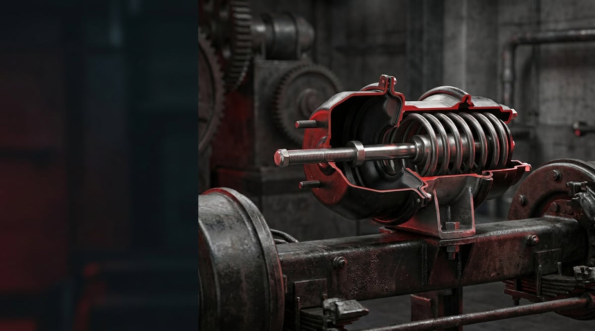
The brake chamber (air chamber) is the actuator that forms the heart of the pneumatic brake system on heavy commercial vehicles: it converts stored air pressure into the mechanical thrust that actually applies the brake. On tractors, trucks and buses the force produced by a single chamber reaches hundreds of kilograms; that is why errors in selection, installation and maintenance directly affect stopping distance and driving safety. This guide addresses, at an expert level, the operation, fault diagnosis, safe replacement and inspection values of the chamber according to heavy diesel vehicle service practice and applicable brake standards such as FMVSS 393.47 and ECE R13.
What Is a Brake Chamber (Air Chamber)? Its Function and Operating Principle
The brake chamber is a fully pneumatic force converter that transmits air pressure through a diaphragm to the push rod, moving the brake slack adjuster (the S-cam or disc caliper mechanism). It is not electronic; it produces force only from the relationship of pressure × effective diaphragm area. Two basic types are used on heavy vehicles:
- Service chamber: Engages when the driver presses the brake pedal. Air pressure pushes the diaphragm, driving the push rod outward and applying the brake; when pressure is released, the return spring pulls the rod back. Chambers with only this type are generally found on the front axles.
- Spring / park (spring brake) chamber: A second-chambered type added behind the service chamber, containing a powerful force spring. It is standard on rear axles and tractors. Here the logic is reversed: when there is air in the system, the spring is compressed and held back by air pressure (brake released), and when air is lost, the spring releases and applies the brake mechanically. Thanks to this fail-safe design, the vehicle is not left without brakes when air is lost; on the contrary, the park/emergency brake engages automatically.
The internal structure of the chamber (cross-section): which part does what?
Picture a combined (service + spring) chamber in cross-section from the front face to the rear; the basic components that make field fault-tracing easier are:
- Push rod and yoke: The external element that transmits the force to the brake slack adjuster; protected by a dust boot (chamber body boot).
- Service diaphragm: The flexible membrane that is pushed by the pressure coming from the service air port. If it tears, there is a continuous air leak and loss of force.
- Return spring: Pulls the service rod back when pressure is released; if it weakens, it causes brake drag.
- Separator (middle) plate and clamp band: The body separating the service and spring chambers; the clamp ring holding the two bodies is the most common point of seal leakage.
- Force (park) spring: The high-tension main spring in the spring chamber. It must be caged before disassembly.
- Spring diaphragm/piston and caging bolt seat: The membrane that holds the park pressure and the area where the bolt that mechanically holds the spring back is seated.
Chambers are sized by push-rod stroke capacity. The common "Type" numbers express the approximate (nominal) effective area of the diaphragm in square inches; this is a design reference, not an exact area value. The most commonly used are Type 20, Type 24, Type 30 (Type 16 and Type 36 are also seen). A larger Type number means, at the same pressure, roughly higher brake force. There are also standard stroke and long stroke (long-stroke / "LS") variants; long-stroke chambers offer a wider adjustment window as the brake pad wears, and the air port on the spring side is square in cross-section (round on standard).
Fault Symptoms and Diagnosis
Chamber faults mostly come from two directions: air leakage (diaphragm/clamp/port) and mechanical weakening (spring fatigue, rod seizing, wrong stroke). Reading the symptom correctly prevents unnecessary part replacement and misdiagnosis.
Symptom 1: Continuous air consumption and the compressor not stopping
With the engine at idle and the brake held applied (or with the park brake released), hissing from the chamber area and a rapid drop in air pressure is typically a torn diaphragm or a leaking clamp seal. The clamp band and air ports are tested with soapy water, looking for bubbles.
Symptom 2: Weak or delayed braking
A partially perforated diaphragm lets some of the pressure escape, so the push rod cannot produce full force; the vehicle "brakes late" or one axle holds weakly. A diaphragm can create brake imbalance (the vehicle pulling to one side) even before it tears completely.
Symptom 3: The park brake will not release or stays locked
If the internal spring in the spring chamber is broken, corroded, or the air passage is blocked, the park brake will not release even though there is air in the system. Conversely, when the spring-retaining structure fails, an unwanted brake application (drag, heating) can be seen while the vehicle is moving.
Symptom 4: Lengthening of the push-rod stroke
Pad wear, a fault in the slack adjuster (automatic adjuster) or spring weakening causes the push rod to extend more than normal at each brake application. Excessive stroke means a drop in brake force and is the most frequently reported non-conformity in roadside inspections.
Symptom 5: Externally visible damage and corrosion
Rusting on the body, a tear in the rod boot (dust boot), mud/water ingress and freezing quickly finish off the internal diaphragm and spring. In a visual inspection, a crack in the chamber boot is an early warning.
When stroke deviates, the mechanism that transfers the chamber's movement is assessed alongside the chamber itself; for how that component works, see our article on the brake slack adjuster.
Table 1 — Symptom / Possible Cause / Check matrix:
| Symptom | Possible Cause | Check / Verification |
|---|---|---|
| Continuous hissing while braking, pressure drop | Torn diaphragm, clamp band seal leak | Apply soapy water to the clamp and ports; watch for bubble formation |
| Weak / unbalanced braking, vehicle pulls to one side | Partial diaphragm perforation, loss of force on one axle | Compare stroke and pressure on an axle basis; pad contact |
| Park brake will not release / locked | Broken spring in the spring chamber, corrosion, blocked air passage | Verify the supply pressure; release manually with the caging bolt |
| Brake applies late, delayed response | Spring fatigue, rod seizing, air line restriction | Application-release timing; free movement of the rod |
| Push rod extends more than normal | Pad wear, adjuster fault, spring weakening | Measure the applied stroke at 90–100 psi; compare with the type limit |
| Crack, rust, water-freezing in the body/rod boot | Torn dust boot, external corrosion, internal wetting | Visual inspection; integrity of the rod boot and body |
| Brake drag, drum/disc overheating | Weak return spring, rod not returning, park partially applied | Observe that the rod fully retracts on release |
How is applied stroke measured correctly?
Stroke measurement is the most critical step in diagnosis and is done as follows:
- Set the conditions: The engine must be off, the park brake released, and the air reservoir in the 90–100 psi (≈6.2–6.9 bar) range. Because the force produced by the diaphragm and the measured stroke change when pressure is outside this range, readings taken at different pressures cannot be compared with one another; for this reason every measurement must be made in the same pressure window.
- Mark the free position: With the brake fully released, mark the point where the rod emerges from the chamber body against a fixed reference that will act as a steel-rule/caliper datum (indelible marker or chalk notch). Choosing a fixed reference point relative to the body, rather than on the rod itself, reduces reading error.
- Apply a full brake: Have a second person press the pedal fully (or fully apply the service line). Mark the outermost (full-out) position of the rod again.
- Measure the difference: Measure the distance between the two marks with a steel rule, caliper or a stroke indicator (marked gauge) made for this purpose. This value is the "applied stroke".
- Compare with the limit: Compare the value found with the FMVSS 393.47 adjustment limit for the chamber's type and stroke type (table below).
Standards and further reading
This subject is governed by the equipment rules for air-braked commercial vehicles. In the United States the federal air brake standard, FMVSS 121 (49 CFR 571.121) defines the reservoirs, protection and timing a compliant system must provide, and Europe applies the equivalent limits of UNECE Regulation No. 13. For further detail, see the illustrated reference guide at airbrakecompressor.com. Always confirm specific figures against the current regulation and the vehicle manufacturer service data.
Outside the United States the equivalent duties sit in national law. In the United Kingdom, regulation 18 of the Road Vehicles (Construction and Use) Regulations 1986 requires every part of the braking system to be maintained in good working order. In Canada, air brake systems fall under the Motor Vehicle Safety Regulations, which contain CMVSS 121.
Replacement / Installation Steps
- Make the vehicle safe: Stop on level ground, switch off the engine, chock the wheels in both directions. Before exhausting the air reservoir, make sure the park brake is physically holding.
- Cage the spring chamber: Using the caging bolt and socket, wind the internal spring back with a hand ratchet (not an impact tool) until the spring is fully compressed. This step zeroes the mechanical force on the rod and makes disassembly safe.
- Exhaust the system air: Discharge the air pressure of the relevant circuit. Mark and disconnect the service and park air lines going to the chamber; check the seals and fittings.
- Undo the connections: Remove the pin connecting the push rod to the slack adjuster (yoke / clevis). Undo the two stud nuts holding the chamber to the brake bracket and remove the chamber.
- Prepare the mounting surface: Clean the mounting flange, studs and brake bracket; remove corrosion, burrs and old gasket residue. Renew any damaged stud.
- Orient the new chamber correctly: Position it at an angle suited to the line geometry of the air ports and to the alignment of the rod with the slack adjuster. The push rod must be set so that it applies force as perpendicular (about 90°) as possible to the slack adjuster; if the angle is off, there is both loss of force and lateral wear.
- Secure and torque: Use the mounting hardware supplied with the new chamber. Bring the stud nuts to the manufacturer's value (typically on the order of ≈195 Nm / 144 ft-lb in heavy diesel applications; always rely on the vehicle/manufacturer specification). If the clamp band is separate, bring the top-bottom bolts to about ≈34 Nm / 25 ft-lb by tightening alternately and evenly.
- Adjust the rod length and stroke: Set the push-rod length so that it gives correct alignment with the slack adjuster in the free position. If there is an automatic adjuster, follow the manufacturer's initial-setup procedure.
- Release the caging: Charge the system with air, and after pressure has built up, undo and remove the caging bolt and place it in its storage seat. Observe that the spring comes to its working position in a controlled way.
- Leak and function test: At 90–100 psi, leak-test all connections with soapy water. In a brake apply-release cycle, verify that the rod extends fully and returns fully, and that the park brake applies and releases. Measure the applied stroke and confirm it is on the safe side of the limit. Carry out a short road test to check for pulling/imbalance.
Points to Watch (Common Mistakes)
- Neglecting the wheel chock: When the park brake is exhausted, the vehicle may be free to move. Letting the air down without chocks is an inescapable risk.
- Caging with an impact wrench: Caging is always done by hand; an impact tool can collapse the spring/body and throw the tool.
- Wrong type or stroke selection: Fitting a smaller type instead of the standard, or the wrong stroke, reduces brake force and creates a non-conformity at inspection. The type, stroke, rod length and flange must match exactly.
- Not centring the diaphragm: On clamp-type chambers, if a dry diaphragm shifts off-centre, it leaks from the band. Dusting the diaphragm with chalk/talc so that it self-centres is a professional method.
- Ignoring the rod angle: If the push rod is not perpendicular to the slack adjuster, there is loss of force, lateral strain and early wear.
- Reusing old/fatigued hardware: Use the studs and nuts supplied with the new chamber; corroded hardware will not hold torque.
- Skipping the dust boot (rod boot): A torn dust boot lets in water and mud, and the most expensive damage begins here. It must be sound at replacement.
- Replacing one chamber and leaving its axle mate: The two chambers on the same axle generally age together; renewing one and leaving the other can create brake imbalance. Evaluate on an axle basis.
Technical Values and Check Points
The stroke adjustment limits below are based on the US federal brake standard FMVSS 393.47(e) "brake adjustment / readjustment limits" table; these values are widely accepted universal references for clamp-type chambers and are consistent with inspection practice under ECE R13. For torque values and model-specific limits, always rely on the vehicle/manufacturer (OE) service document and the DIN/ECE approval label; the exact value may vary by manufacturer.
Applied stroke adjustment limits — FMVSS 393.47(e)
Table 2 — Maximum applied stroke (adjustment) limit for clamp-type chambers. Source: FMVSS 393.47(e). The values are normative in inches; the mm equivalents are rounded.
| Chamber Type | Standard Stroke Limit | Long Stroke (LS) Limit |
|---|---|---|
| Type 16 | 1¾" (≈44 mm) | 2" (≈51 mm) |
| Type 20 | 1¾" (≈44 mm) | 2" (≈51 mm) |
| Type 24 | 1¾" (≈44 mm) | 2" (≈51 mm) * |
| Type 30 | 2" (≈51 mm) | 2½" (≈64 mm) |
| Type 36 | 2¼" (≈57 mm) | — (generally standard stroke) |
* In FMVSS 393.47(e) the standard long-stroke Type 24 limit is 2" (≈51 mm); only for the special Type 24 LS variant with a 3" nominal stroke is the limit separately defined as 2½" (≈64 mm). The nominal stroke stamped on the chamber body must be taken as the basis. These values are inspection (adjustment) limits; in good practice the brake should be readjusted or serviced before it reaches the limit (generally about 6 mm / ¼" below the limit). A stroke that reaches the limit means a serious drop in brake force.
Measurement and installation check points
- Measurement pressure: Engine off, reservoir 90–100 psi (≈6.2–6.9 bar). Outside this window gives incomparable readings.
- Stud nut torque: Typically on the order of ≈195 Nm (144 ft-lb) in heavy diesel applications; confirm the manufacturer's value.
- Clamp band torque (separable type): Alternately and evenly, around ≈34 Nm (25 ft-lb).
- Push-rod angle: Approximately perpendicular (90°) to the slack adjuster; there must be no bind in the free and applied positions.
- Free stroke (free travel): The rod's play up to first contact should be small and within the manufacturer's tolerance; excessive free stroke points to a slack-adjuster/mechanism problem.
- Axle balance: The stroke and response values of the two chambers on the same axle should be close to each other.
- Is the reservoir at 90–100 psi? Engine off, wheels chocked?
- Is the spring chamber caged (not an impact tool)?
- Is the applied stroke ≥6 mm below the type's FMVSS limit?
- Is the push rod ~90° to the slack adjuster?
- Is the soapy-water test clean at all connections?
- Are stroke/response balanced with the axle-mate chamber?
Maintenance and Service Life
The brake chamber is long-lived when correctly installed; the main factors determining its life are moisture/corrosion, continuous operation under excessive stroke, and air system cleanliness.
- Periodic visual inspection: At every major service, inspect body corrosion, rod dust-boot tears, and clamp band and port-area leakage by eye and with soapy water.
- Stroke monitoring: The stroke lengthens as the pad wears. Regular stroke measurement shows the health of both the brake and the automatic adjuster early. A stroke approaching the limit requires checking the pad and adjuster too, before blaming the chamber.
- Air quality: Moist/dirty air corrodes the internal spring and diaphragm from the inside. Timely replacement of the air dryer cartridge directly extends chamber life.
- Winter conditions: Water entering through the dust boot freezes and blocks the diaphragm and rod. A sealed dust boot and regular draining are critically important.
- Replacement logic: Although repair with a diaphragm/clamp repair kit is possible, complete chamber replacement is a safer choice for spring chambers and corroded bodies; a spring-containing body should not be safely opened in the field.
- Quality and equivalent selection: OE-equivalent, ECE R13 / DIN approved chambers stand apart from cheap equivalents in diaphragm material, spring cycle life and body corrosion resistance. The brake is a safety item, not a cost item.
Choosing the Right Chamber (Type / Stroke Guide)
The aim in replacement is to keep exactly the type and stroke class fitted to the vehicle at the factory. Chambers are offered in type/stroke options covering service and combined (service + spring) applications, so that class has to be read off the vehicle before anything is ordered. The guide table below helps you quickly determine the correct class; for the exact selection, rely on the stamp on the chamber body and the vehicle's OE number.
Table 3 — Chamber type/stroke selection guide (by application).
| Application | Typical Type / Configuration | Stroke Class | Common Location |
|---|---|---|---|
| Service chamber (single diaphragm) | Type 20, Type 24 | Standard or LS | Front axle |
| Combined spring park chamber | Type 20/24, Type 24/24 | Standard or LS | Rear axle (truck/bus) |
| Heavy tractor / high load | Type 30/30, Type 24/30 | Mostly LS | Tractor rear axles |
| Trailer / semi-trailer | Type 24/24, Type 30/30 | Standard or LS | Semi-trailer axles |
On combined chambers, a designation such as "24/30" indicates the service (24) chamber type first and then the spring (30). When selecting an OE equivalent, cross-matching can be done with the reference systems on the market (e.g. Knorr-Bremse, ZF/WABCO, Haldex type numbering); however, final verification is always done by an exact match of the four-part set of type + stroke type + rod length + flange/stud spacing. The body stamp and the OE catalogue reference together are what let you confirm the correct equivalent against these four criteria, so record both before ordering.
The correct type, a sound diaphragm-spring structure and a corrosion-resistant body are the basis for a brake chamber working safely for years. For the service and spring-park applications of heavy commercial vehicles, fit a chamber whose type and stroke repeat the original exactly and that carries the ECE R13 / DIN approval marking; when you select the correct type, the installation and inspection steps in this guide provide long-lived, balanced brake performance. For the rest of the wheel end and the air supply feeding it, the VADEN ORIGINAL range covers brake caliper bellows covers and seals, brake caliper sensor covers and sensor repair kits, air dryers and desiccant cartridges, relay valves and brake valves.
Shop this part: Brake Bellows
Main guide: Brake Chamber: Fault Diagnosis, Replacement and Maintenance Guide
Tags
Frequently Asked Questions
- When should a brake chamber be replaced?
- It should be replaced in cases of diaphragm leakage (continuous hissing, pressure drop), the park brake failing to release/locking due to a broken spring, body corrosion, or excessive stroke that reaches the FMVSS limit and cannot be corrected by adjustment. Visual damage (rod boot tear, rust) is an early warning signal.
- What is the difference between Type 20, 24 and 30?
- The number expresses the approximate (nominal) effective area of the diaphragm in square inches; a larger number means roughly higher brake force at the same pressure. The correct type is determined by the vehicle and axle load class. The wrong type creates either insufficient braking or a balance problem; the type must be kept exactly the same at replacement.
- Can standard and long-stroke (LS) chambers be used interchangeably?
- No, they are not swapped arbitrarily. An LS chamber offers a wider stroke window and is recognised on the spring side by a square air port. Whichever stroke type the vehicle was built to at the factory must be kept; mixed use disrupts brake balance and the adjustment tolerance. Each type's FMVSS 393.47 adjustment limit is also different.
- What does the caging bolt do?
- It mechanically holds back and makes safe the high-tension spring in the spring park chamber. It both ensures safety before removing the chamber and serves to manually release a park brake that has locked due to air loss at the roadside. It is always turned by hand; it is never used with an impact tool.
- Who measures the push-rod stroke, and at what value does it alarm?
- The measurement is made with the engine off and the reservoir at 90–100 psi, using a steel rule/caliper or a stroke indicator. When the applied stroke approaches the FMVSS 393.47 limit for the chamber's type/stroke type (in practice about ¼" / 6 mm below the limit), the brake should be readjusted or serviced. A stroke that has reached the limit indicates that brake force has dropped noticeably and that a non-conformity will arise at inspection.
- Should one chamber or both chambers on the axle be replaced?
- Since the chambers on the same axle age under similar conditions, renewing one and leaving the other increases the risk of brake imbalance. Especially if the corrosion and stroke values are close, evaluating on an axle basis and, if necessary, replacing both, gives a safer result.
- What should I read from the stamp on the chamber body?
- The type number (e.g. 20, 24, 30), stroke type (standard/LS), the service/spring chamber types on combined chambers, and usually the manufacturer/approval mark (ECE/DIN) are stamped on the body and clamp ring. In spare-part selection, this stamp must be verified together with the rod length and flange dimension.
- Why must the push rod sit roughly perpendicular to the slack adjuster?
- To avoid loss of force and lateral wear. The rod is set so that it applies force as close to 90 degrees as possible to the slack adjuster; when the angle is off, part of the force strains the mechanism sideways instead of applying the brake, and wear starts early. After fitting, confirm the rod does not bind in either the free or the applied position.
- Does a longer stroke always mean the chamber has to be replaced?
- No. The stroke lengthens naturally as the pad wears, so a reading close to the limit calls for checking the pad and the automatic slack adjuster first. Repeat the measurement with the engine off and the reservoir at 90–100 psi. Replace the chamber only once its own fault is confirmed, such as diaphragm leakage, a broken spring or body corrosion.
- I fitted a new diaphragm but it still leaks at the clamp band. What causes that?
- Usually the diaphragm has shifted off-centre; on clamp-type chambers a dry diaphragm leaks from under the band. Dust it with chalk or talc so that it self-centres. If the clamp band is separable, tighten the top and bottom bolts alternately and evenly to about 34 Nm (25 ft-lb), then repeat the soapy-water test at 90–100 psi.
Related Articles

Air Dryer: Faults, Replacement & Maintenance Guide
How a truck air dryer's charge and purge cycle keeps moisture and oil out of the brake system, and what a hissing purge valve or water in the tanks means.
Air Brake Chamber Explained: Types, Sizes, Failure Symptoms & Replacement
Truck and trailer inspection reports rarely say the brake chamber is defective; they report brake force imbalance. Chamber types, sizes, symptoms and replacement.
How to Read an Air Brake Diagram: Circuit Guide
How do you read an air brake system diagram? Symbol language, line colours, port codes, circuit split, trailer lines and fault-tracing, step by step.


