Air Brake Compressor: Faults, Replacement & Maintenance Guide
On a truck, a slow-filling reservoir or oil in the dryer often starts at the compressor's cut-in/cut-out cycle, not the compressor body: diagnosis and care.
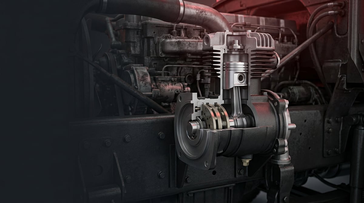
On heavy commercial vehicles the braking system runs entirely on compressed air; the heart that produces this air is the engine-driven air brake compressor. When the compressor weakens on a tractor unit or a bus, the result is not merely a "slow-filling reservoir": it triggers a chain of problems such as extended pressure build-up time, low-pressure warnings, oil passing and premature saturation of the air dryer. In shop-floor language, this guide brings together the operating logic of the compressor for heavy diesel vehicles, fault diagnosis, correct replacement practice and safe technical values.
What Is an Air Brake Compressor? Its Function and Operating Principle
The air brake compressor is a piston-type pump that, on a heavy commercial vehicle, is driven by the engine and compresses atmospheric air to produce the compressed air the brake system needs to operate. The air it produces passes through the air dryer and fills first the wet (supply) reservoir and from there the reservoirs of the front and rear brake circuits. The compressor is driven from the engine by gears, a belt-and-pulley, or a direct crankshaft/camshaft connection, and is usually single- or twin-cylinder. On heavy diesels this unit works on the same principle as the equivalents of Bendix Tu-Flo and Knorr-Bremse type compressors; the VADEN product family is likewise manufactured to replace these OE-type designs.
The compressor turns continuously, but it does not pump air continuously. Three components manage the system together:
- Compressor: The unit that physically compresses the air.
- Governor (pressure regulator): The valve that reads reservoir pressure and switches the compressor between "loaded" (pumping air) and "unloaded" (not pumping air, via the unloader) modes.
- Unloader mechanism: The device that, using pilot air from the governor, holds the inlet valves open and stops the cylinder from pumping air.
How does the cut-in / cut-out cycle work?
When reservoir pressure reaches the upper limit (cut-out), the governor engages and, by feeding the unloader, takes the compressor off load; the compressor turns but does not pump air. When pressure drops to the lower limit (cut-in), the governor cuts off the pilot air, the unloader closes, and the compressor begins pumping air again. This cycle keeps pressure within a narrow band for as long as the engine runs. In a typical heavy commercial system, cut-out is around 8.6 bar (125 psi) and cut-in around 6.9 bar (100 psi); the governor generally cuts in 1.4–1.7 bar (20–25 psi) below cut-out. These values are consistent with the typical ranges given in Bendix and Knorr-Bremse service bulletins; the exact setting varies by vehicle manufacturer and governor model.
Why is a "normal" amount of oil carried over?
In a piston compressor, a very small amount of oil vapour mixing into the discharged air to lubricate the rings and valves is a natural part of the design. This "normal oil carry-over" is captured by the desiccant and oil separator in the air dryer and is expelled at every cut-out by the dryer's automatic purge pulse. The problem begins when this amount exceeds the design limit — that is, when the rings/cylinder wear.
OE-equivalent types and vehicle–engine matching
What determines the correct compressor choice is the engine family, drive type (gear/belt), single or twin cylinder, and the required air delivery. The table below is a guiding match for common heavy commercial platforms.
| Vehicle family (example) | Engine family | Typical compressor type | Cylinder / delivery tendency |
|---|---|---|---|
| Mercedes-Benz Actros / Antos | OM 470 / OM 471 | Knorr-Bremse type (e.g. LK family equivalent) | Single or twin cylinder, medium–high delivery |
| Volvo FH / FM, Renault T | D11 / D13 | Knorr / Wabco type equivalent | Twin cylinder, high delivery |
| Scania R / S | DC13 / DC16 | Knorr type equivalent | Twin cylinder, high delivery |
| MAN TGX / TGS | D26 (D2676) | Knorr type equivalent | Single / twin cylinder |
| DAF XF / CF | MX-11 / MX-13 | Knorr / Wabco type equivalent | Twin cylinder |
| Iveco Stralis / S-Way | Cursor 11 / 13 | Knorr type equivalent | Single / twin cylinder |
| North American tractors | Cummins / Detroit | Bendix Tu-Flo 550 (single) / Tu-Flo 750 (twin) equivalent | Single or twin cylinder |
Fault Symptoms and Diagnosis
Most compressor faults fall under three main headings: oil passing, insufficient/delayed pressure and overheating/noise. The critical point is this: the same symptom (for example a slow-filling reservoir) can stem from the compressor, from the governor, or from a leak in the system. That is why diagnosis should be done by isolating the system before removing the compressor.
| Symptom | Possible Cause | Check / Verification |
|---|---|---|
| Reservoir fills very slowly (long build-up time) | Worn rings/cylinder, clogged air filter, leaking valve plate, system leak | Measure the 85 - 100 psi build-up time (should be ≤40 s); address system leakage first; check the inlet filter |
| Excess oil in the air dryer and reservoirs / oil film at the outlet | Worn rings and cylinder surface, overheating, blocked engine oil return line | Inspect the dryer purge outlet and wet-reservoir drain; use a standard oil-carry-over test instead of a subjective "card test" |
| Pressure does not reach the cut-out value or never cuts out | Governor fault, unloader sticking, exhaust line leak | First disable the governor and test; if the problem persists, remove and inspect the unloader mechanism |
| Compressor constantly runs "labouring", head temperature rising | Unloader stuck closed, restricted/blocked discharge line, carbon build-up | Monitor head and discharge-line temperature; check the discharge line for carbon/flake build-up |
| Irregular cycling, unstable pressure readings | Intermittently operating unloader, governor pilot line leak | Check the governor pilot line and the unloader piston seals |
| Carbon crusting in the discharge line, quickly saturated dryer | Chronic oil carry-over + high discharge temperature | Compressor condition test + inspection of the discharge line and dryer cartridge |
Distinguishing the oil-passing symptom
A small amount of oil carry-over is normal; that is why "there is oil at the outlet" does not by itself condemn the compressor. There is a genuine oil-carry-over fault when oil re-accumulates shortly after a fresh dryer service, together with carbon flakes in the discharge line and a slow-filling system that has no obvious leak. In diagnosis, a standard oil-carry-over test (e.g. a measuring-cup method similar to Bendix BASIC) should be preferred over a subjective eyeball judgement.
Distinguishing the insufficient-pressure / long-build-up symptom
An extended pressure build-up time is the first warning. But before blaming the compressor, isolate the system: with the brakes released, measure the leakage rate. If leakage is within limits and the inlet filter is clean, slow filling is most likely caused by worn rings or a scored cylinder surface.
Distinguishing the overheating / noise symptom
A steady, muffled "labouring" sound and a rising head temperature most often point to an unloader valve stuck closed — because the compressor cannot be unloaded, it pumps continuously. A restricted or wrongly routed discharge line also raises head temperature and turns the oil to carbon; these two feed one another.
How the first signs a driver notices from the cab map onto these three headings is summarised in the air compressor failure symptoms article.
Standards and further reading
This subject is governed by the equipment rules for air-braked commercial vehicles. In the United States the federal air brake standard, FMVSS 121 (49 CFR 571.121) defines the reservoirs, protection and timing a compliant system must provide, and Europe applies the equivalent limits of UNECE Regulation No. 13. For further detail, see the illustrated reference guide at airbrakecompressor.com. Always confirm specific figures against the current regulation and the vehicle manufacturer service data.
Readers outside the United States should work from their own national framework: in the United Kingdom the braking system must be maintained under regulation 18 of the Road Vehicles (Construction and Use) Regulations 1986, and in India the governing rules are published by the Ministry of Road Transport and Highways.
Replacement / Installation Steps
The steps below are a general sequence for heavy diesel (truck/tractor/bus); always follow the torque and procedure values in the service manual for the vehicle and compressor.
- Make the system safe: Park the vehicle on level ground, chock it, shut down the engine, and fully drain all air reservoirs from their drain valves. Do not disconnect any connection before the pressure is at zero.
- Mark the connections: Photograph and label the inlet (engine intake or air filter connection), discharge, governor pilot line, coolant (on water-cooled types) and lubrication lines.
- Disconnect the lines: Separate the discharge, inlet, governor and any water/oil lines. Cap all open ports to prevent dirt/water from entering the system.
- Release the drive connection: On gear-driven types remove the gear/flange; on belt-driven types remove the pulley and tensioner. On gear drive, note the timing marks.
- Remove the old compressor: Undo the mounting bolts and lower the compressor while supporting it. Do not underestimate its weight; use appropriate lifting.
- Clean the mounting surface and lines: Clean off old gasket residue from the flange surface. Be sure to check the discharge line; if it is clogged with carbon, clean or replace it — otherwise the new compressor will also fail quickly.
- Fit the new compressor and a new gasket: Always use a new gasket/O-ring. Seat the compressor and tighten the mounting bolts to the manufacturer's torque, gradually and in a crosswise sequence (see the "Technical Values" section for typical ranges).
- Connect the drive: On gear drive, align the timing marks; on belt drive, set pulley alignment and belt tension to the manufacturer's value.
- Connect lubrication and cooling: Connect the pressurised lubrication line; if necessary, pre-prime with oil before first start so the line does not run dry. On water-cooled types, connect the cooling circuit and bleed the air lock.
- Reconnect the lines: Correctly connect the inlet, discharge and governor pilot lines. Make sure the discharge line is as short as possible, continuously downward-sloping and without loops (this reduces condensation and carbon build-up).
- First start and check: Start the engine and check all connections for leaks with soapy water. Verify the build-up time, cut-in/cut-out pressures and the dryer purge pulse.
Points to Watch (Common Mistakes)
- The "oil at the outlet = compressor is finished" fallacy: A small amount of oil carry-over is normal. Before replacing the compressor, verify with a standard oil-carry-over test; the problem may also be the dryer cartridge or a blocked oil return line.
- Blaming the compressor without testing the governor: If pressure does not cut out or the cycle is disturbed, check the governor and unloader first. Most "the compressor won't pump" cases are actually caused by the governor or unloader.
- Wrong routing of the discharge line: An upward-looping, long or restricted line collects condensation and raises temperature. The line should be short, downward-sloping and free-flowing.
- Overlooking belt tension: On belt-driven types, a loose belt leads to slippage and low delivery, while an over-tight belt shortens bearing life.
- Diagnosing without measuring system leakage: Before pinning slow filling on the compressor, always run a leak test; the real culprit is often a leak in the circuit.
- Not cleaning the old gasket surface properly: Remaining gasket residue leads to leaks and having to disassemble again.
Technical Values and Check Points
The values below are general/safe references for common heavy commercial vehicle systems. Critical values such as cut-in/cut-out, torque and discharge temperature vary by vehicle and compressor model; for exact figures, always rely on the relevant service manual.
| Parameter | Typical / Safe Reference | Note |
|---|---|---|
| Governor cut-out (upper) pressure | ~8.6 bar (125 psi) | Varies by model |
| Governor cut-in (lower) pressure | ~6.9 bar (100 psi) | ~1.4–1.7 bar (20–25 psi) below cut-out |
| Build-up time (85 - 100 psi) | ≤ 40 seconds | At above-idle speed; longer means loss of efficiency |
| System leakage (brakes released) | Single vehicle < 2 psi/min, combination < 3 psi/min | Must be measured before diagnosis |
| Low-pressure warning | ~4.1–4.5 bar (60–65 psi) | The warning light/buzzer should activate below this band |
| Discharge line / head temperature | Should not rise excessively | High temperature turns oil to carbon; a sign of restriction/blockage |
The build-up (≤40 s) and leakage limits above (single vehicle <2 psi/min, combination <3 psi/min) are consistent with widely accepted service and inspection references for heavy commercial brake systems; the leakage limits align with the roadside-inspection criteria derived from FMVSS 121, and the build-up and cycle values with Bendix and Knorr-Bremse service bulletins. For the type approval and minimum performance of the brake system, the applicable regulation in the EU is ECE R13 / (EU) 2015/68. Regional regulations and vehicle-manufacturer values always take precedence.
Typical mounting torque and tightening sequence
The torque of the compressor mounting bolts varies with bolt size, class (8.8/10.9) and flange design. The values below are general references only; for exact torque and tightening sequence, always use the vehicle/compressor manual.
| Bolt (size / class) | Typical dry torque range | Note |
|---|---|---|
| M8 / 8.8 | ~22–25 Nm | General reference |
| M10 / 8.8 | ~43–48 Nm | General reference |
| M10 / 10.9 | ~60–65 Nm | High-strength bolt |
| M12 / 8.8 | ~75–85 Nm | General reference |
| M12 / 10.9 | ~105–115 Nm | High-strength bolt |
Quick field check points
- Measure the build-up time with a stopwatch; if it is lengthening, look first at leakage, then the inlet filter, then the compressor condition.
- At every cut-out you should hear a clear purge pulse (air-water discharge) from the dryer; if not, check the dryer/purge valve.
- Observe the liquid coming from the wet-reservoir drain: excessive oil is a sign of chronic carry-over.
- Check the discharge line by hand (when cold) and by eye; if there are carbon flakes or hardened residue, the line should be renewed.
Maintenance and Service Life
Compressor life depends largely on two things: clean intake air and low discharge temperature. Both directly affect oil carry-over and carbon formation. A routine that keeps preventive maintenance simple extends the life of both the compressor and the air dryer and valves behind it.
- Daily / pre-trip: Observe build-up and cut-out, verify the low-pressure warning, drain the reservoirs. On self-lubricated types, check the oil level.
- Periodic (at PM/DOT services): Record the build-up time, verify the purge pulse, scan the clamps and lines, and evaluate the reservoir drain results (water/oil).
- Oil and lines: On some self-lubricated types the oil is changed periodically (within the manufacturer's interval, e.g. at a given mileage/operating hours with the appropriate SAE-grade oil). On pressure-lubricated types, engine oil quality and an open return line are critical.
- Air dryer cartridge: Renew the cartridge within the manufacturer's interval. A saturated cartridge cannot hold oil and moisture; this leads to corrosion in the reservoirs and valve faults.
- Intake source: Keep the inlet filter/line clean. A dirty intake both reduces delivery and increases oil consumption.
When chronic oil carry-over, recurring carbon build-up and a lengthening build-up with no leak are seen together, it is time to overhaul or replace the compressor. In most heavy commercial applications, complete replacement rather than overhaul is a more reliable solution with a lower total cost; in that case, renewing the discharge line and dryer cartridge at the same time significantly extends service life. The governor and unloader ahead of the compressor and the air dryer behind it are parts of the same system; to prevent a recurring fault, evaluate these components together as well.
After correct diagnosis and a clean installation, what matters is that the compressor you fit meets the tolerances and durability of the OE-type design. The VADEN Air Brake Compressor family is developed as an equivalent to Bendix Tu-Flo and Knorr-Bremse type units on heavy diesel trucks, tractors and buses, to meet the safe technical values and field expectations in this guide; you simply need to choose the model suited to your needs, together with the vehicle and engine match, evaluating it as a whole alongside the VADEN air dryer and governor product groups.
Vehicles and engines mentioned in this guide: MAN D2676 · Volvo D13 · Volvo D11 · DAF MX-13 · DAF MX-11 · Volvo FM · Volvo FH · Mercedes-Benz Antos
Shop this part: Air Compressor
Deciding which adapters, plugs and hoses encountered during removal should be renewed is handled separately in the compressor connection hardware guide.
All our technical guides on this topic
- Air Brake Compressor: The Heart of the Heavy-Duty Vehicle Air System
- Air Compressor Failure Symptoms: No Air Pressure or Compressor Pumping Oil
- Truck Air Compressor by Engine & Make: DD15, Cummins, PACCAR, Mack & More
- Clutched Air Brake Compressor: Faults, Replacement, Care
- Single vs Twin-Cylinder Air Compressor: Choice & Fitment
- Compressor Connection Hardware: Faults, Replacement, Care
- Compressor Crankshaft & Drive Assembly: Failure & Replacement Guide
- Compressor Piston-Ring & Connecting Rod: Repair Guide
- Truck Air Compressor Overhaul Kit: Head, Valve Plate, Gasket
- Compressor Cooling Plate & Water Cooling: Faults, Repair & Care
- Compressor Repair and Gasket Kit: Faults, Replacement, Care
- Compressor Valve & Unloader: Fault, Replacement & Care Guide
VADEN ORIGINAL products
- Air Brake Compressors — 5085 products
- Air Brake Compressor Repair Kits — 4521 products
- Compressor Repair Kit — 1230 products
- Air Compressor — 564 products
Tags
Frequently Asked Questions
- Is it normal to see a little oil at the compressor outlet?
- Yes, a very small amount of oil carry-over is a natural part of a piston compressor and is needed to lubricate the rings/valves. The air dryer holds this oil and purges it out at every cut-out. The problem begins when oil re-accumulating shortly after a fresh dryer service, carbon flakes in the discharge line and a slow-filling system are seen together.
- Is the compressor always the reason a reservoir fills slowly?
- No. The most common culprit is a leak in the system. First measure the leakage rate with the brakes released (single vehicle <2 psi/min, combination <3 psi/min). If leakage is within limits and the inlet filter is clean, then a loss of efficiency from worn rings/cylinder is likely.
- Is it the governor or the compressor that is faulty? How do I tell them apart?
- If pressure never cuts out, does not reach cut-out, or the cycle is irregular, check the governor and unloader first. If the problem clears when the governor is disabled, the culprit is the governor/unloader; if it still won't pump air, remove and inspect the unloader mechanism.
- The compressor overheats and constantly labours — what could cause this?
- The most common cause is an unloader valve stuck closed — because the compressor cannot be unloaded, it pumps continuously and head temperature rises. A restricted or wrongly routed discharge line also raises the temperature. Since high temperature turns oil to carbon, these two problems feed one another.
- Is it essential to replace the discharge line when fitting a new compressor?
- Even if not strictly essential, it is strongly recommended. The oil pumped by the old compressor accumulates as carbon in the discharge line and partly blocks it. If you fit a new compressor without cleaning this build-up, the rising temperature will quickly make the new unit pass oil as well. At the very least clean the line, and if there is carbon crusting, renew it.
- What torque should I tighten the compressor mounting bolts to?
- The exact torque varies by vehicle and compressor model; the service manual always takes priority. To give a general idea, common values are around ~43–48 Nm for an M10 8.8 bolt and ~75–85 Nm for an M12 8.8 bolt. Tighten the bolts gradually and in a crosswise sequence; for gasket sealing, do not go to full torque in one step.
- Should I have it overhauled or replace it completely?
- The decision depends on the degree of wear and on cost. If the cylinder surface is heavily scored and the ring grooves are worn, an overhaul may be short-lived. In heavy commercial use, complete replacement is generally more reliable and more economical overall; renewed together with the discharge line and dryer cartridge, it gives the longest life.
- What should the cut-in and cut-out pressures normally be?
- On a typical heavy commercial system, cut-out is around 8.6 bar (125 psi) and cut-in around 6.9 bar (100 psi), with the governor generally cutting in 1.4–1.7 bar (20–25 psi) below cut-out. These ranges match the typical figures published in Bendix and Knorr-Bremse service bulletins. The exact setting varies by vehicle manufacturer and governor model, so the service manual always has the final word.
- There is no purge pulse from the dryer at cut-out — what does that mean?
- At every cut-out you should hear a clear purge pulse, an air-and-water discharge, from the air dryer. If you cannot, check the dryer and the purge valve. The dryer captures the oil and moisture the compressor normally carries over and expels them each cycle; a saturated cartridge can no longer do this, which leads to corrosion in the reservoirs and valve faults. Renew the cartridge within the manufacturer's interval.
- How does a dirty inlet filter affect the compressor?
- A dirty intake both reduces delivery and increases oil consumption, so the reservoirs fill more slowly while the compressor carries over more oil. Compressor life depends largely on clean intake air and a low discharge temperature. That is why, when build-up time lengthens, you should look at leakage first, then the inlet filter and line, and only then at the condition of the compressor itself.
Related Articles
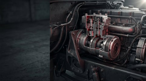
Clutched Air Brake Compressor: Faults, Replacement, Care
Clutched air brake compressors on trucks: how the clutch works, telling a slipping clutch from a worn compressor, replacement steps and torque values.
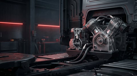
Single vs Twin-Cylinder Air Compressor: Choice & Fitment
Learn how to match single or twin-cylinder air brake compressors to your truck: flow demand, drive and cooling interfaces, fault diagnosis, replacement steps.
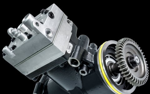
Truck Air Compressor by Engine & Make: DD15, Cummins, PACCAR, Mack & More
When a tractor unit comes into the shop with a note that simply says "compressor job", the thing that decides how long the work will actually take is usually


