Exhaust Manifold: Cracks, Leaks, Replacement & Torque Guide
Spot exhaust manifold cracks, gasket leaks and broken studs on heavy trucks. Learn diagnosis, correct replacement steps, torque values and tightening sequence.
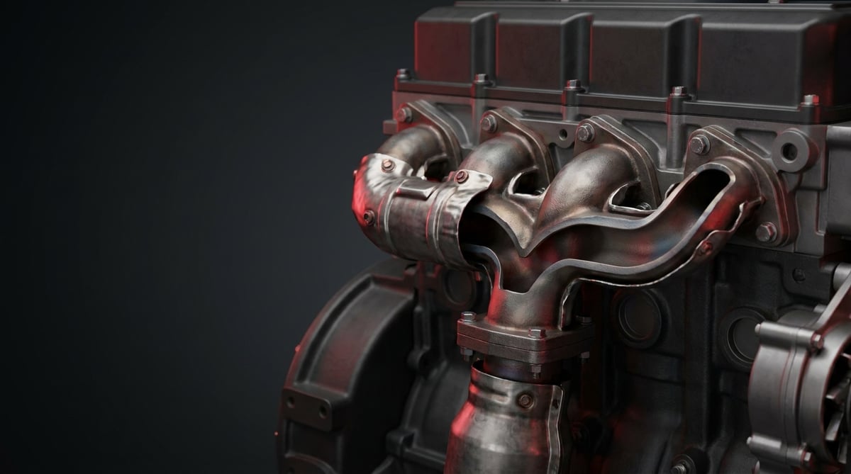
Behind the power a heavy commercial vehicle engine produces and the efficiency of its turbocharger, there is often an unseen but critical component: the exhaust manifold. This cast part, which collects the scorching exhaust gas leaving the cylinders and channels it to the turbocharger, is one of the components exposed to the engine's hottest and most demanding thermal cycle. When a tractor unit or a bus develops a cracked manifold, a gasket leak or a broken stud, the result is not merely a "hissing noise": a chain of problems appears, such as power loss, delayed turbo response, rising exhaust temperature and increased fuel consumption. This guide brings together, in field language, the operating logic of the exhaust manifold for heavy diesel vehicles, fault diagnosis, correct replacement practice and safe technical values.
What Is an Exhaust Manifold? Its Function and Operating Principle
The exhaust manifold is a component made of cast iron or cast steel, designed to withstand high temperatures and thermal cycling, that collects the burnt gases leaving the exhaust port of each cylinder in a heavy diesel engine into a single duct and channels them to the turbine inlet of the turbocharger. Although its job appears simple, its conditions are harsh: from a cold engine the manifold heats up to several hundred degrees within minutes, cools rapidly when the engine stops, and this heating-cooling cycle repeats every time. This constant expansion and contraction is the main factor causing thermal fatigue in the material.
In heavy commercial engines the manifold is designed to feed the turbocharger and preserve exhaust energy even at low engine speeds. In international usage the part is referred to in German as Abgaskrümmer or simply Krümmer, and in English as exhaust manifold. The VADEN product family is also manufactured to replace these OE-type designs, with the same connection dimensions and thermal-durability targets.
Although the manifold looks like a single cast piece, in heavy diesel engines the design is often specialized to manage thermal stress. Its main components and design features are as follows:
- Cast body (single-piece or segmented): On long inline 6-cylinder engines the manifold is often cast in 2–3 pieces (segmented), so that each segment expands on its own and the total thermal stress is reduced.
- Expansion gaps / slip connections: The sliding gaskets or slip rings between segments allow the parts to expand thermally relative to one another, preventing cracking.
- Manifold gaskets: High-temperature-resistant metal/composite gaskets between the cylinder head and the manifold that ensure gas sealing.
- Studs, bolts and nuts: The fasteners that attach the manifold to the cylinder head, working in a hot and corrosive environment.
- Turbo flange: The gasketed interface where the manifold outlet connects to the turbocharger turbine housing.
Why segmented casting and expansion gaps?
Along a long 6-cylinder bank, a single-piece manifold elongates on the order of a centimeter when heated end to end. When this elongation is restrained, the material "relieves" itself by cracking. The segmented design and the sliding gaskets between segments prevent exactly this: each part expands freely, and the total stress is distributed across several points. That is why, during assembly, paying attention to these expansion gaps and the correct positioning of the sliding gaskets is the key to preventing cracks.
Material: cast iron or cast steel?
Classic heavy diesel manifolds are made of gray cast iron or spheroidal graphite (nodular/SG) cast iron; these provide good thermal mass and vibration damping. In applications exposed to higher exhaust temperatures (especially in modern EURO engines running with EGR and at high loads), heat-resistant cast steel (e.g. SiMo-type alloys) is preferred. Material selection directly affects thermal-fatigue life; on an aftermarket part it is critical that the material grade is compatible with the OE.
Single-piece or multi-piece? Engine matching
The determining factors in selecting the correct manifold are the engine family, the number of cylinders and their layout, the segment structure (single-/multi-piece) and the turbo flange type. The table below is a guiding match for common heavy commercial platforms.
| Vehicle family (example) | Engine family | Typical manifold structure | Material tendency |
|---|---|---|---|
| Mercedes-Benz Actros / Antos | OM 470 / OM 471 | Segmented (multi-piece), with sliding gaskets | SiMo cast steel / nodular cast iron |
| Volvo FH / FM, Renault T | D11 / D13 | Multi-piece, with expansion gaps | Heat-resistant cast iron/steel |
| Scania R / S | DC13 / DC16 | Segmented casting | Nodular cast iron / SiMo |
| MAN TGX / TGS | D26 (D2676) | Multi-piece, with slip rings | Cast iron / cast steel |
| DAF XF / CF | MX-11 / MX-13 | Segmented, with expansion gaps | Heat-resistant casting |
| Iveco Stralis / S-Way | Cursor 11 / 13 | Multi-piece casting | Nodular cast iron |
Fault Symptoms and Diagnosis
Exhaust manifold faults fall under three main headings: cracking (thermal fatigue), gasket leak and stud/bolt failure. The critical point is this: the same symptom (for example a hissing noise or power loss) can originate from a manifold crack, a gasket leak, or a broken stud. For this reason, diagnosis should be carried out before removing the part, by tracing the source of the noise and the location of the leak through the difference between cold and hot conditions.
| Symptom | Possible Cause | Check / Verification |
|---|---|---|
| "Tick-tick / puff-puff" noise on cold start, diminishing as it warms up | Manifold gasket leak or small crack (the gap is open when cold, closes as it expands when hot) | With the engine cold, search for the leak point by ear and hand (carefully, from a distance); observe how the noise changes as it heats up |
| Continuous hissing noise, exhaust smell | Gasket leak, loosened/broken stud, body crack | With the engine idling, look for soot/carbon traces and leak noise around the connection |
| Power loss, delayed turbo response (turbo lag), poor response | Pressure leak before the turbo — a crack or gasket leak is losing exhaust energy | Assess the boost pressure and turbo response; check the manifold-turbo interface |
| Exhaust gas temperature (EGT) higher than expected | Turbo efficiency is low due to the leak, and the engine injects more fuel to compensate | Compare the EGT reading against the reference; investigate the increase in fuel consumption |
| Soot/carbon build-up in the connection area, black trace | Soot trace left by hot gas leaking from the gasket (visual evidence of the leak) | Look for a dry carbon line on the manifold-head and manifold-turbo surfaces |
| Vibrating metallic noise, loose feel | Broken or loosened stud/bolt; the manifold is not seating fully | Check all studs/nuts visually and with a torque wrench; look for any that are missing/broken |
| Visible crack or discoloration in the engine bay | Thermal-fatigue crack, overheated zone | Clean the body when cold and inspect for cracks (especially at port corners and the flange) |
Identifying the cracking (thermal fatigue) symptom
The most typical sign of manifold cracks is a "tick-tick" noise that becomes pronounced on a cold start and eases as the engine warms up. When cold, the crack/gap is open and gas escapes through it; as the material expands, the gap partly closes and the noise diminishes. This behavior distinguishes a crack from a steady mechanical noise. Cracks most often begin at the corners of the cylinder ports and at segment/flange transitions. To be sure, clean the body while cold and inspect it visually; fine cracks reveal themselves with a carbon line.
Identifying a gasket leak
A gasket leak usually leaves a continuous hiss and a dry, black carbon line on the connection surface. If there is a trace on the surface between the manifold and the cylinder head, the gasket is suspect; if there is a trace on the flange between the manifold and the turbo, the turbo flange gasket is suspect. A leak often comes together with a loosened stud or a warped flange surface; therefore, replacing only the gasket does not solve it—surface flatness and the fasteners must also be checked.
Identifying stud / bolt failure
In a hot and corrosive environment, studs become brittle over time and break; a broken stud causes the manifold not to seat fully against the head in that area, thus leading to a leak and a vibrating metallic noise. While checking all nuts with a torque wrench, you may notice that one or several "turn freely" or that there is a broken stud in place. Trying to force out a broken stud can strip the threads; it should be removed with heat, penetrating oil and the correct technique.
Further reading
For a plain-language technical overview of this subject, see the reference article on Wikipedia. Always confirm specific figures and procedures against the vehicle manufacturer service data.
Replacement / Installation Steps
The following steps are a general sequence for heavy diesel vehicles (truck/tractor/bus); always rely on the torque and procedure values in the vehicle's and engine's service manual.
- Cool the engine and make it safe: Park the vehicle on level ground, chock it, disconnect the battery terminal (if necessary) and wait for the engine to cool completely. Never work on a hot manifold.
- Gain access: Remove or move aside the turbocharger, exhaust pipe connection, heat shields, EGR connections and any obstructing air/fuel lines according to the manual. Photograph and label everything you remove.
- Disconnect the turbo and exhaust connection: Remove the manifold-turbo flange and, if present, the exhaust brake/flap. Cap the open ports to prevent foreign matter from entering the system.
- Assess the studs/nuts: Apply penetrating oil before loosening the nuts holding the manifold. Loosen them in sequence and gradually from the outside inward; note any corroded or broken studs.
- Remove the old manifold and gasket: Undo the nuts and lower the manifold while supporting it. On segmented types, note the position of the parts relative to one another and the orientation of the sliding gaskets. Remove the old gaskets.
- Extract broken studs: Remove broken studs with heat + penetrating oil + an extractor, without stripping the threads. Use a new stud set if necessary. If the thread seat is damaged, apply a helicoil/thread repair.
- Clean the surfaces and check for cracks: Clean old gasket residue, carbon and roughness from the cylinder head and manifold flange surfaces. Check the flatness (warp) of the head surface with a straightedge/feeler gauge. If the existing part is being refitted rather than a new manifold, inspect it for cracks.
- Fit the new gasket and studs: Always use a new gasket; fit the gasket in the correct orientation and dry (without applying silicone/sealant unless the manufacturer states otherwise). If the manufacturer permits, apply high-temperature anti-seize to the threaded part of the studs—this makes the next removal easier.
- Fit the manifold, mind the expansion gap: On segmented types, join the parts and sliding gaskets in the correct orientation; take care to keep the thermal expansion gaps free. Seat the manifold in place and start the nuts by hand.
- Apply torque in sequence and in stages: Tighten the nuts to the manufacturer's torque from the center outward, in stages (e.g. 50% - 100%). This sequence ensures the flange seats properly and the gasket seals; the wrong sequence leads to warping and early leaks.
- Reconnect the turbo, exhaust and shields: Connect the turbo flange with a new flange gasket, and refit the heat shields, EGR and exhaust line. On first start, check for leaks (noise/soot) at idle; after a brief warm-up, cool it down and re-check the torque as specified by the manufacturer (re-torque).
Points to Watch (Common Mistakes)
- The "the noise stops once it warms up, no big deal" misconception: A tick-tick noise that appears when cold and diminishes when hot is often the first sign of a real crack or gasket leak; postponing it enlarges the leak and the power loss.
- Replacing only the gasket without checking surface flatness: A new gasket placed on a warped flange surface soon leaks again. Surface flatness and stud condition must be checked.
- Reusing old/corroded studs: Studs that have been through the heat-corrosion cycle become brittle; using a new stud/nut set at replacement prevents the fault from recurring.
- Skipping the anti-seize: Studs without high-temperature anti-seize applied to the threaded part break at the next service and double the work. (Watch the manufacturer's friction/torque requirement.)
- Not renewing the turbo flange gasket: When the manifold is removed, the turbo interface gasket should also be renewed; if the old gasket is refitted, the pre-turbo leak continues.
- Wrong gasket/part number: EURO 5 and EURO 6, or a different engine variant, may require a different manifold/gasket; do not fit it without verifying against the OE number.
Technical Values and Check Points
The values below are general/safe references for common heavy commercial vehicle engines. Critical values such as torque, tightening sequence and exhaust temperature vary by vehicle and engine model; for exact figures always rely on the relevant service manual.
| Parameter | Typical / Safe Reference | Note |
|---|---|---|
| Manifold surface temperature (under load) | High — on the order of several hundred °C | Varies with engine load and speed; the thermal cycle is the real stressor |
| Exhaust gas temperature (EGT, before turbo) | General reference ~500–700 °C band | Varies by model; a sudden rise is a sign of a leak/efficiency drop |
| Flange surface flatness (warp) | Within the manufacturer's tolerance (very low deviation) | Check with a feeler gauge; if out of tolerance, the surface must be machined/the part replaced |
| Manifold-turbo interface pressure | Must be leak-free | A leak shows itself as a boost drop and turbo lag |
| Visible crack / carbon trace | Must not be present | Port corners and flange transitions are the riskiest zones |
| Expansion gap / sliding gasket | Must be able to move freely | A jammed gap = crack risk |
The EGT band and temperature statements above are only guiding general references; in modern EURO 6 engines the values differ markedly depending on EGR and load conditions. In terms of exhaust emissions and sealing, the type-approval framework in force in the EU is taken as the basis (e.g. EURO 6 / (EU) 595/2009 and the related implementing regulations). Regional regulations and vehicle-manufacturer values always take priority.
Typical nut/stud torque and tightening sequence
The torque of manifold nuts varies with the stud size, grade and flange design. The values below are only a general reference; for exact torque and tightening sequence, always use the vehicle/engine manual.
| Stud/nut (size / grade) | Typical torque range | Note |
|---|---|---|
| M8 / 8.8 | ~20–25 Nm | General reference; the use of anti-seize affects the torque |
| M10 / 8.8 | ~40–50 Nm | General reference |
| M10 / 10.9 | ~55–65 Nm | High strength |
| M12 / 8.8 | ~75–90 Nm | General reference |
| M12 / 10.9 | ~100–120 Nm | High strength |
Quick field check points
- On the first cold start, listen for the tick-tick / hissing noise; observe how it changes as it warms up (distinguishing a crack from a steady leak).
- Look for a dry black carbon line on the manifold-head and manifold-turbo surfaces; this is the clearest visual evidence of a leak.
- Assess the boost pressure and turbo response; delayed boost may indicate a pre-manifold leak.
- Scan all nuts with a torque wrench; verify whether there is any freely turning nut or broken stud.
- Clean the body while cold and look for cracks at the port corners and flange transitions.
Maintenance and Service Life
The service life of an exhaust manifold depends largely on two things: the severity of the thermal cycle and the health of the fasteners. The manifold is not a "wearing" part; what finishes it off is repeated sudden heating-cooling together with corrosion. For this reason, preventive maintenance is less about the part itself and more about regularly monitoring the gasket, studs and turbo interface around it.
- Periodic visual inspection: At services, review the manifold body, the flanges and the turbo interface for carbon traces and cracks.
- Fasteners: Periodically check the nut torques; loosening is the harbinger of a leak that begins at a single point.
- Heat shields: Keeping the heat shields in place and intact protects the surrounding lines and sensors and supports thermal management.
- Gasket-renewal discipline: Whenever the turbo or manifold is removed, renew the relevant gaskets; an old gasket is not reused.
- Cooling-down habit: Running the engine at idle for a while after a heavy load allows the turbo and manifold to cool gradually, reducing thermal shock.
If a visible crack, a tick-tick noise that stops once warm, a persistent carbon trace and a boost loss are seen together, it is time to replace the manifold. Repairing a cracked cast manifold by welding is often not a permanent solution in heavy diesel applications; the thermal cycle causes the weld zone to crack again. For this reason, in heavy commercial use, complete replacement is generally more reliable and, overall, more economical. When renewing the manifold, replacing the gasket set and the corroded studs at the same time prevents the fault from recurring and gives the longest service life.
After correct diagnosis and a clean installation, the decisive factor is that the manifold you fit meets the material grade, thermal durability and connection dimensions of the OE-type design. The VADEN Exhaust Manifold family has been developed as an aftermarket equivalent of OE-type (Abgaskrümmer / exhaust manifold) units on heavy diesel trucks, tractor units and buses, to meet the safe technical values and field expectations in this guide; you simply need to select the model suited to your needs together with vehicle and engine matching, evaluating it as a whole with the gasket and fastener sets in the VADEN Engine product group.
Shop this part: Exhaust Manifold
Related categories: Exhaust Manifold · Exhaust Manifold
Related technical guides: Engine Cylinder Head Group: Faults, Replacement & Maintenance · Exhaust / Engine Brake: Faults, Replacement & Maintenance Guide · Oil Cooler: Failure Symptoms, Replacement & Maintenance Guide · Truck Oil Pan Group: Faults, Replacement & Maintenance Guide · Engine Valve Train & Adjustment Shim: Faults, Replacement, Care
Application and compatibility: Vehicle compatibility catalogue · Engine compatibility catalogue
Vehicles and engines mentioned in this guide: MAN D2676 · Volvo D13 · Volvo D11 · DAF MX-13 · DAF MX-11 · Volvo FM · Volvo FH · Mercedes-Benz Antos
Main guide: What Is an EGR Valve? Failure Symptoms and Cleaning (Heavy Commercial Vehicles)
Tags
Frequently Asked Questions
- How do you tell if an exhaust manifold is cracked?
- The most typical sign is a "tick-tick" or "puff-puff" noise that becomes pronounced when the engine is cold and diminishes as it warms up. When cold, the crack is open and gas escapes; as the material expands, the gap partly closes and the noise softens. In addition, a dry black carbon trace on the connection and body, power loss and a rising exhaust temperature may accompany it. For a definitive diagnosis, the body should be cleaned while cold and inspected visually, especially at the port corners and flange transitions.
- What are the symptoms of a manifold gasket leak?
- A continuous hissing noise, an exhaust smell, a dry black carbon line on the connection surface and power loss over time are the most common symptoms. If there is a trace on the surface between the manifold and the cylinder head, the manifold gasket is suspect; if there is a trace on the flange between the manifold and the turbo, the turbo flange gasket is suspect. A leak often comes together with a loosened stud or a warped surface.
- Does an exhaust manifold leak cause power loss and turbo lag?
- Yes. The manifold carries exhaust energy to the turbocharger; a crack or gasket leak loses part of this energy before the turbo. The result is delayed turbo response (turbo lag), low boost, loss of responsiveness and a rising exhaust temperature as the engine injects more fuel to compensate. As the leak grows, the power loss and the increase in fuel consumption become more pronounced.
- Why does a manifold stud break, and how is a broken stud removed?
- Studs become brittle in the constant high-temperature and corrosion cycle and break over time; studs at the ends in particular are at risk. A broken stud should be removed with heat (controlled), penetrating oil and a stud extractor, without stripping the threads. If the thread seat is damaged, a thread repair (helicoil) is applied. Using a new stud set at replacement and applying high-temperature anti-seize to the threaded part makes the next removal easier.
- Can a cracked exhaust manifold be repaired by welding?
- Although in some cases it can be welded temporarily, in heavy diesel applications welding a cast iron/steel manifold is often not a permanent solution. The thermal cycle causes internal stress and re-cracking in the weld zone. For this reason, in terms of reliability and total cost, complete replacement is recommended for a cracked manifold.
- In what sequence and to what torque should I tighten the manifold when fitting it?
- The exact torque and sequence vary by vehicle/engine model; the service manual is always the priority. The general rule is to tighten the nuts from the center outward, in stages (e.g. 50% then 100%). Common reference values are around ~40–50 Nm for an M10 8.8 stud and ~75–90 Nm for an M12 8.8. If you are using anti-seize, apply the manufacturer's lubricated-torque value and re-torque after the first warm-up if required.
- If a leak persists even though I fitted a new gasket, what could be the cause?
- The most common causes are uneven seating on a warped flange surface, a loosened or broken stud, and a turbo flange gasket that was not renewed. Replacing only the gasket is not enough: the flatness of the cylinder head and manifold surfaces must be checked, the fasteners renewed and the torque applied in the correct sequence. In addition, a fine body crack that was overlooked can also keep the leak going.
- What does the expansion gap (sliding gasket) do, and should I close it?
- On segmented manifolds, the expansion gaps and sliding gaskets between the parts allow the parts to elongate freely as they heat up, preventing cracking. Compressing or closing these gaps "to make it solid" produces the opposite effect: the restrained expansion cracks the material through thermal fatigue. The gaps are part of the design and must remain free.
- Why does the material grade matter when choosing a replacement exhaust manifold?
- Because thermal fatigue, not wear, ends a manifold's life, and that depends directly on the material. Classic heavy diesel manifolds are gray or spheroidal graphite (nodular/SG) cast iron, which give good thermal mass and vibration damping. Applications exposed to higher exhaust temperatures, especially modern EURO engines running EGR at high load, use heat-resistant cast steel such as SiMo-type alloys. On an aftermarket part the grade must remain compatible with the OE.
- What can I do to extend the service life of an exhaust manifold?
- Watch the parts around the casting rather than the casting itself. At each service, inspect the body, flanges and turbo interface for carbon traces and cracks, check the nut torques periodically, and keep the heat shields in place and intact. Renew the relevant gaskets every time the turbo or manifold comes off. After a heavy load, idle the engine briefly so the turbo and manifold cool gradually, which reduces thermal shock.
Related Articles

Oil Filter Cap and Housing: Leaks, Cracks and Seal Replacement
Truck engine oil filter cap and housing: why plastic caps crack, O-ring leak causes, bypass valve faults, and correct torque and seal replacement steps.
Piston Rings: Oil Consumption, Compression Loss and Replacement
Ring-related oil consumption and compression loss in truck diesel engines: how rings seal, blow-by and leak-down tests, ring gap and replacement.
Intake Manifold and Intake Pipe: Faults, Diagnosis, Repair
How the intake manifold and charge air pipe work on truck diesel engines, how to spot boost leaks, run a pressure test and fit them leak free.


