Air Compressor No Air or Pumping Oil: Diagnostic Guide
Compressor or system? The pressure build-up test that separates no-air and oil-pumping faults on truck air brakes, plus a pre-replacement checklist.
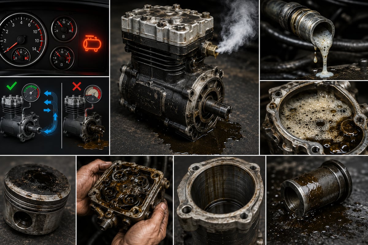
Across a fleet yard, the first move of the morning gets delayed: the ignition comes on, the pressure gauges sit in the red, the parking brake won't release, and the driver waits in the cab while the engine idles for minutes on end. The diagnosis that comes back over the radio is always the same: "the compressor's gone." Pull the same truck's overnight log, though, and the picture changes: the system was at full pressure when it was parked for the night, and most of that pressure is gone by morning. In other words, air was produced — it just wasn't held. This guide isn't a parts list; it's a diagnostic flow. It walks through the two typical field complaints, "no air pressure" and "pumping oil," and shows how to sort them into the right branch before the compressor ever comes off the truck.
Two symptoms, one question: is production short, or is the system losing air?
A compressed-air system does three separate jobs: it produces, it conditions, and it holds. The compressor is only responsible for the first of these — storing the air is the tank's job, drying it is the dryer's job, and distributing and containing it is the job of the valves. Almost every misdiagnosis in the field comes from skipping this distinction, because when a driver says "no pressure," that one phrase can mean a production shortfall, a loss downstream, or simply a faulty gauge.
The same applies to the oil complaint. A piston-type air compressor is lubricated with engine oil, and by design it carries a very small amount of oil vapor into the compressed air; the dryer's oil-separation stage is built to manage exactly that amount. So the real question isn't "is oil getting through" — it's "is the amount getting through more than the system can manage," and, more importantly, "what is forcing the compressor to pass that much oil in the first place."
That's why the diagnostic flow splits into two branches here. But both branches pass through the same front door: before you touch the compressor, you need to prove that the system actually holds air, and that the compressor is genuinely turning under load. Skip that proof and every replacement you make just repeats the same fault with a new part a short time later. The driver's sentence describes a behavior, not a part — and diagnosis starts by turning that behavior into a number.
Pressure build-up time: the one measurement that splits the diagnosis
The backbone of the split is the build-up time measurement. The goal is to record how long the system takes to climb from a defined low pressure up to the regulator's cut-out point, and compare that against the value in the OE manual. This isn't a hunt for one absolute number — it's far more useful read against the same truck's own history and against a sister vehicle on the same route.
- Secure the vehicle on level ground, chock the wheels, and apply the parking brake correctly.
- In addition to the dash gauge, connect a calibrated pressure gauge to the wet tank and to the circuit outlets. Relying on the dash gauge alone is the most common mistake — the fault can sit in the measurement chain itself.
- Drain the tanks through their petcocks and catch the liquid in a clean container for inspection. Clear water, a milky emulsion, and dark oily sludge each point to something very different; this observation feeds into the oil branch later.
- Bleed the pressure down to the starting level the OE manual specifies. If the manual gives no starting value, pick the same two pressure points and time the interval between them, repeating the exact same condition on every run.
- Start the engine and hold it at the fixed rpm the manual specifies. A different rpm changes the time directly — a reading taken at idle cannot be compared with one taken at higher rpm.
- Start the stopwatch, watch the climb through to the cut-out point, and record the time. Also note whether the climb is steady or slows once it passes a certain pressure.
- Watch for the moment the regulator cuts out and listen for the dryer's purge. If cut-out never happens, the fault isn't in production but in the control side, and the time measurement loses its meaning.
- Stop the engine, leave the vehicle exactly as it is, and take the pressure drop after a set period as a second reading. Repeat the reading with the brake pedal held and released; the difference between the two narrows down which circuit the leak is in.
The result falls into three categories. If build-up is slow and there's no drop, the fault is on the production side and you move to the compressor branch. If build-up is normal and the drop is significant, the compressor is innocent — the system is losing air it's already holding. If build-up is slow and the drop is significant at the same time, close the leak first and re-run the measurement; you can't measure production capacity in the shadow of a large leak.
There's a fourth outcome, and it's the most misleading one: pressure climbs quickly up to a point, then stops climbing. This behavior usually points to a valve-plate leak, a restricted discharge line, or an unloader circuit that isn't closing fully; because the loss grows as pressure rises, production ends up balanced out by the loss at some point.
Ruling out the system: static leaks, the dryer, and the valve side
Before moving to the compressor branch, you need to prove the system actually holds air. The static leak test is simple: bring the system up to full pressure, stop the engine, and watch the pressure drop over a set period. If the drop is above what's expected, look for the source in sequence — by ear, with soapy water, and by isolating circuits. In heavy-duty vehicles the usual leak points are well known: line fittings and elbows, trailer coupling heads, brake chambers and their seal assemblies, air-suspension bellows and the leveling valve, the parking brake valve, the four-circuit protection valve, the dryer's purge valve, and the regulator's control line.
The connecting hardware between the compressor outlet and the dryer is the quietest part of that list; fittings, adapters, plugs, and hose surfaces fatigue under vibration and heat, and even a very small leak here keeps the compressor under constant load. For fault symptoms, removal order, and assembly discipline for this group, see the compressor connection hardware guide; in the diagnostic flow, these parts are ruled out before the compressor itself.
The dryer side deserves its own heading, because it's the most common impostor for a "compressor won't build" complaint. When the purge valve gets dirty and sticks open, or when the regeneration cycle runs long, the system vents a significant share of the air it just produced. The symptom looks exactly like a production shortfall: pressure climbs slowly, the compressor runs almost constantly, and a purge sound is heard often out in the field. For the dryer's purge behavior, cartridge life, and heater circuit, the air dryer guide gives a detailed check sequence.
Once the system side is ruled out, the flow splits in two: if pressure builds slowly with no leak found, move to the "no air" branch; if there's an abnormal oil trace in the tanks or at the dryer outlet, move to the "pumping oil" branch. It isn't rare for both branches to be open at once — an excessive duty cycle both lowers production capacity and increases oil carryover.
The "no air" branch: tracing the flow from the intake side
The rule for this branch is to follow the air's path from start to finish: intake, compression, discharge. Breaking that order wastes time, because looking inside the compressor is the most expensive step and, most of the time, unnecessary.
The intake side is the first place to check. The compressor draws its air either from the engine's intake side or from its own filter. A restricted intake reduces the air mass taken in on every stroke and directly lengthens build-up time. The usual suspects: a clogged air filter, a collapsed or internally delaminated intake hose, a crushed pipe, a dirty compressor filter, and foreign debris pulled into the intake. A hose delaminating internally is especially sneaky — it can look sound from the outside yet collapse under load, so the fault only shows up at higher rpm.
The discharge side is second, and it's the most commonly overlooked cause in heavy-duty vehicles. The discharge line carries hot, oil-vapor-laden air from the compressor outlet to the dryer. If the line is routed poorly, made from the wrong material, or the truck has run a high duty cycle for a long time, coke builds up on the inner surface. The narrowing bore first raises discharge temperature, the rising temperature speeds up coke build-up, and the process feeds itself. The result: pressure builds slowly, the compressor overheats, and oil carryover increases — which is why the discharge line is, as a rule, cleaned or renewed at the same time the compressor is replaced.
The unloader circuit comes third. Once cut-out pressure is reached, the regulator unloads the compressor with an air signal. If the signal line is leaking, the inside of the regulator is dirty, or the unloader piston isn't returning, the compressor keeps turning but stops pumping air into the system. The check is simple: disconnect the control line and watch the behavior, then confirm the signal actually arrives at cut-out pressure.
| Check point | What you see or measure | What the finding means |
|---|---|---|
| Intake filter and hose | Contamination, collapse, internal delamination, a crushed section | Restricted intake, low air mass per stroke |
| Discharge line inner surface | Coke layer, narrowed bore, excessive temperature | Back-pressure has risen, efficiency has dropped |
| Regulator and control line | Whether the cut-out signal is present, whether the line leaks | The unloader circuit isn't taking the compressor off load |
| Dryer purge valve | Continuous blow-off, a dirty valve seat | Produced air is being vented, production is innocent |
| Tank petcocks | Stuck open, frozen, held open by dirt | System isn't filling, the loss sits downstream of the tank |
| Cylinder head and valve assembly | Back-blow from the intake, an overheating head | Valve-plate leak, compressed air flowing back |
| Drive group | Belt slip, clutch not engaging | Compressor isn't turning at sufficient rpm |
Valve plate and cylinder head gasket: the center of a no-build fault
Once the intake, discharge, and control sides are ruled out, attention turns to the compressor itself. The group that actually determines compression efficiency is the valve plate: the plate holding the intake and discharge valves, their springs, and their seating surfaces. When this group degrades from coking, fatigue, or thermal stress, compressed air leaks back into the cylinder or out through the intake side; the result is a compressor that turns but can't build pressure.
The field symptoms are recognizable. Hold a hand near the intake opening and you'll feel a steady back-pulse; the compressor head runs unusually hot; build-up time stretches out dramatically past a certain pressure; and even an unloaded compressor gives off a faint hiss. Once the group is stripped down, you'll typically find a cracked valve reed, pitting on a seating surface, a lost spring, or coke keeping a valve from closing fully. Dark, hard, glossy deposits on the surfaces are usually the signature of excessive discharge temperature — in other words, a high duty cycle.
The cylinder head gasket, meanwhile, is the source of two entirely separate fault families, because inside the head, air passages and coolant passages run right next to each other. If the gasket is breached between the two passages, the direction of the leak can go either way. If compressed air leaks into the cooling circuit, you'll see bubbling and level movement in the expansion tank, and pressure will still show up in the circuit even after the engine has stopped. If coolant leaks into the air side, instead of clear condensate the tank drain will yield a colored, slippery liquid with a different smell; coolant residue quickly damages valves and the dryer cartridge.
To tell the two possibilities apart, the character of the drained liquid is decisive: normal condensate is clear and odorless, a milky emulsion points to oil mixing with water, and a colored, slippery liquid suggests coolant crossing over. Before deciding, weigh the coolant level history and any external leak trace together — pulling the head is the last step, not the first.
The drive side: is the compressor actually turning?
This is the question most often skipped in the diagnostic flow. However sound the compressor is, it can't produce enough air if it isn't turning at the right rpm without interruption. Heavy-duty vehicles use two basic drive types: gear drive taken directly off the engine's timing gear, and belt drive.
In belt-driven systems the fault develops gradually. If the belt has glazed, the tensioner has weakened, or the pulley surface is worn, the compressor turns normally unloaded but slips under load. Build-up time therefore only stretches out while the system is actually filling; a short spin-up on an empty system can still look normal. Watch the belt's behavior under load and check the pulley grooves and the tensioner's freedom of movement. Black dust around the belt track, a hot pulley, and a short squeal under load round out this picture.
With clutched compressors, the picture changes completely. In this design the compressor is engaged and disengaged through a clutch according to system demand; the point is to cut the fuel and wear cost of a compressor that spins unloaded. If the clutch doesn't engage, the compressor never builds any pressure at all, and the picture looks exactly like "the compressor is dead" — even though the compressor itself is perfectly sound. Whether the engagement signal is arriving, and the condition of the clutch face and its control, call for a separate check sequence; the clutched compressor guide walks through it in detail. On a clutched vehicle, starting diagnosis by pulling the compressor housing is, more often than not, an unnecessary teardown.
Gear-drive faults are rarer but more serious. Wear on the drive gear, increased backlash, or a loose mounting bolt both hurts air production and carries a risk of secondary damage on the engine side. An irregular knock from the housing, an oil leak at the block mounting, and a metallic sound tied to gear backlash are the signs of this group — in this case the engine side needs to be assessed as well, before the compressor comes off.
The "pumping oil" branch: how does oil escape the compressor?
The first rule of this branch is setting the right expectation. A piston compressor carries an oil film on the cylinder wall, and a very small amount of oil vapor inevitably mixes into the compressed air. The fault isn't the presence of oil — it's the quantity: dark oily sludge from the tank drain, oil pooling at the dryer outlet, oily valve outlets, and a cartridge that saturates far sooner than expected are what open this branch.
Worn piston rings and sticking piston rings are the best-known cause, but they're two different things. Worn rings have reached the end of their mechanical life and usually come with high mileage. Sticking rings, on the other hand, are glued into their grooves by coked oil — the result of high discharge temperature, in other words an excessive duty cycle or a restricted discharge line. In the second case, replacing the compressor only postpones the fault.
Scoring and out-of-round wear on the cylinder wall is the second mechanism, and it's usually the signature of dirty intake air — grit pulled in through the intake acts like sandpaper. If the intake source isn't corrected in this case, the new part follows the same path. A blocked oil return line is the third: if the return path carrying pressurized oil back to the engine crankcase narrows, oil pools inside the housing and gets pushed past the rings into the air side — meaning heavy oil carryover can show up even while the compressor is mechanically sound.
Excessive crankcase pressure is the fourth mechanism, and the one most often misdiagnosed; on most designs the compressor's crankcase is tied to the engine crankcase, and rising pressure pushes oil toward the compressor and blocks its return path. In this picture, the real fault is in the engine. Incorrect oil level and the wrong oil grade is the fifth mechanism: an overfilled crankcase, long idling on a grade, and an oil outside the OE approval all directly increase oil carryover.
Standards and further reading
This subject is governed by the equipment rules for air-braked commercial vehicles. In the United States the federal air brake standard, FMVSS 121 (49 CFR 571.121) defines the reservoirs, protection and timing a compliant system must provide, and Europe applies the equivalent limits of UNECE Regulation No. 13. For further detail, see the illustrated reference guide at airbrakecompressor.com. Always confirm specific figures against the current regulation and the vehicle manufacturer service data.
Readers outside the United States should work from their own national framework: in the United Kingdom the braking system must be maintained under regulation 18 of the Road Vehicles (Construction and Use) Regulations 1986, and in India the governing rules are published by the Ministry of Road Transport and Highways.
Crankcase pressure, oil return, and level: three quiet causes
In the oil branch, the three most productive checks are the ones you can do without ever pulling the compressor. The first is crankcase ventilation. If the engine's breather element or hose is blocked, crankcase pressure rises; the simple tells are a strained oil filler cap, a dipstick pushed out of its seat, and seals that have just started weeping. Once the breather path is cleared, the compressor's oil carryover can drop noticeably.
The second is the oil return line. Check the feed and return connections, hoses, and any transition adapters for grade and crushing. The return line has to be routed so oil can flow back to the crankcase by gravity; a low elbow, a crushed section, or coke build-up blocks that flow.
The third is oil level and grade. Confirm the level was checked with the vehicle on level ground and following the OE procedure, and make sure the oil's viscosity grade and approval list match the vehicle. In a compressor exposed to high discharge temperature, the wrong oil cokes much faster and sets the stage for sticking rings.
| Mechanism | Typical observation | How to confirm |
|---|---|---|
| Ring wear | High mileage, dark oily sludge in the tanks | Cylinder and ring inspection, oil-consumption record |
| Sticking rings | Overheated discharge line, hard glossy deposits | Duty-cycle measurement, discharge-line inner inspection |
| Cylinder-wall scoring | Dust trace on the intake side, filter fault | Audit of the intake source and filter history |
| Blocked oil return line | Oil pooling in the housing, dryer saturating quickly | Remove the line and test its flow |
| Excessive crankcase pressure | Oil cap under strain, dipstick pushed out | Check the crankcase ventilation path |
| Excess oil level or unsuitable oil | Level above the top mark, early coking | Re-check on level ground, compare against approval list |
| Excessive duty cycle | Compressor loaded almost continuously | Leak survey and consumption inventory |
| External seal leak | Wetness outside the housing, drip trace | Clean and re-observe, rule out an internal path |
Where does the escaped oil go, and what does it damage?
This is the most important part of the oil branch, because replacing the compressor doesn't take back the oil that's already gotten into the system. Escaped oil travels with the air and passes through, in order: the discharge line, the dryer, the wet tank, the circuit protection valve, the distribution lines, the control and relay valves, the brake chambers, the air-suspension bellows, and the pneumatic auxiliary circuits.
The first casualty is the dryer. Once the cartridge's desiccant is coated in an oil film, its moisture-holding capacity drops fast; the result is more moisture getting through to the system and hose lines starting to freeze in winter. A cartridge saturating far earlier than expected is usually the first sign that the compressor is carrying oil — which is why, in a system where oil has been found, the cartridge is renewed in the same job as the compressor.
The valve groups come second. The seals and diaphragms inside pneumatic valves swell, harden, or soften on continuous contact with oil. The symptom is easy to recognize: brakes releasing late, valves hissing, a delayed response from the parking brake control, and erratic trailer supply behavior. The same mechanism also shortens the life of the brake chambers and the air-suspension bellows; the bellow material changes size and elasticity once it contacts oil.
The tanks come third. Oily sludge collecting at the bottom of the tank holds the petcock and traps water that can't be drained. This is the start of the most dangerous chain in winter: oil carryover, a saturated cartridge, moisture in the system, a frozen line, and lost brake function.
Duty cycle: why loaded running increases oil carryover
Duty cycle is the share of a given time period the compressor spends loaded — that is, actually compressing air. The compressor keeps turning even when it's unloaded, but it doesn't pump air; the loaded time is what actually generates the heat and wear. This concept is the most common yet least-discussed cause behind a "pumping oil" complaint.
The connection works like this: the more time the compressor spends loaded, the higher discharge temperature climbs; as temperature rises, the oil film on the cylinder wall thins, oil in the ring grooves cokes, and coke builds up in the discharge line. A coked groove sticks the ring, a sticking ring passes more oil, the extra oil produces more coke in the line, and the narrowing line raises temperature once more. In other words, a high duty cycle sets up a self-feeding cycle of deterioration. Under continuous-duty conditions the industry generally wants duty cycle to stay under roughly a quarter; the real threshold for a given vehicle depends on the engine, compressor capacity, and tank volume, and is stated in the OE documentation.
Most of what pushes duty cycle up sits outside the compressor: a large number of small leaks, seepage at trailer coupling heads, a dryer that purges continuously, add-on consumers, and stop-and-go city driving. Lowering duty cycle before replacing the compressor is the single most important thing you can do for the new part's service life.
Symptom, measured value, likely cause, and first action
The table below brings both branches' check points together on a single decision surface. The rule for using it is simple: pick the row, measure first, let the measurement narrow the likely cause, and only then touch a part.
| Symptom | Measured value | Likely cause | First action |
|---|---|---|---|
| Pressure never builds at all | Time to reach cut-out pressure | Drive disconnected, clutch not engaging, a petcock left open | Confirm the compressor is turning and all drains are closed |
| Pressure builds very slowly | Build-up time and intake restriction | Intake blocked, discharge line narrowed, valve plate leaking | Check intake and discharge line, re-measure the time |
| Stops climbing past a certain pressure | The kink point in the pressure curve | Valve-plate leak, or the unloader isn't closing fully | Check for intake back-blow, test the regulator signal |
| Pressure drops overnight | Pressure drop rate with the engine off | Static leak, a valve or chamber seal leaking | Run a circuit-by-circuit leak survey |
| Compressor almost never stops | Duty-cycle ratio | Leak, an added consumer, continuous purging | Build a consumption inventory, close the leak |
| Discharge line runs excessively hot | Line temperature behavior and bore | Coke build-up and high duty cycle | Clean or renew the line, bring the duty cycle down |
| Dark oily sludge at the tank drain | Character of the drained liquid | Compressor is carrying oil, cartridge is saturated | Move to the oil branch, plan a cartridge change |
| Colored, slippery liquid at the drain | Liquid character and coolant level | Cylinder head gasket breached to the water side | Monitor coolant level and the expansion tank |
| Brakes release late | Release time and valve inner surface | Valve seals swollen from oil | Shut off the oil source, inspect affected valves |
| Lines freeze in winter | System moisture level and drain log | Dryer capacity reduced by oil | Drain the tanks, trace the oil source |
| Dash gauge disagrees with the test gauge | Comparison against a calibrated gauge | Fault in the gauge, sensor, or control line | Verify the measurement chain, rebuild the diagnosis |
System-side causes mistaken for air compressor failure
A significant share of the compressors replaced in the field are actually sound. It isn't unusual for a part pulled under the label "air compressor failure" to test within tolerance, because every one of the following looks identical from the driver's seat.
A faulty regulator is first: if cut-out pressure has settled low, the system never fully fills; if it never cuts out at all, the safety valve takes over instead, and now the complaint becomes "it keeps venting air." A dryer that purges continuously is second, and because it vents produced air straight back out, it's a near-perfect impersonation of a production shortfall. A tank petcock stuck open or frozen open is third — especially in winter, ice can hold a petcock open and the truck never builds pressure at all.
A leak at the trailer supply line or coupling head is fourth: the tractor behaves normally on its own, and the picture falls apart once the trailer is coupled. A faulty four-circuit protection valve is fifth, and its typical sign is one circuit not filling, or all circuits filling far too slowly.
A fault in the measurement chain is sixth, and the most frustrating of all. If the dash gauge, the pressure sensor, or the line feeding the sensor is faulty, the actual pressure can be correct while the gauge simply reads wrong — which is why the first step in the diagnostic flow is always to hook up a calibrated gauge. Add-on consumers are seventh: an auxiliary circuit with a leaking control silently drains the system's air and keeps the compressor under constant load. These seven items need to be ruled out before the compressor comes off the truck; ruling them out costs a few hours of measurement, while skipping that costs a new part and a repeat fault.
What to check before you replace the compressor
Even when diagnosis points to the compressor, the part shouldn't go in before the list below is complete. The reason is simple: in a system-side fault, the new compressor meets the same fate, and the fault log grows into "the second compressor didn't hold up either."
- Leak survey must be complete and static pressure drop brought down to an acceptable level; a compressor fitted while a leak is still open goes into a high duty cycle from day one.
- Duty cycle must be measured, and if it's high, the cause must be found. Add-on consumers, continuous purging, and the trailer side are each assessed separately.
- The discharge line must be removed and its inner surface inspected. If there's coke build-up, clean or renew the line; the old line doesn't go back onto the new compressor.
- The dryer cartridge — and the dryer assembly, if needed — must be renewed; in a system where oil has been seen, a saturated cartridge strains the new part from day one.
- All tanks must be drained, checked for oily sludge on the inner surface, and the petcocks confirmed to move freely.
- The intake source must be checked: air filter, hose integrity, clamps, and the compressor's own filter if it has one. Dirty intake air is a direct cause of cylinder wear.
- The oil feed and return lines must be removed and their flow tested; the return line is checked for grade, crushing, and blockage.
- Engine crankcase ventilation must be checked; a compressor fitted without correcting high crankcase pressure starts carrying oil in short order.
- Coolant-side connections must be inspected, and if the compressor is water-cooled, flow must be confirmed unobstructed; otherwise discharge temperature runs out of control.
- The regulator, the unloader control line, and the drive group must be tested: belt, tensioner, and pulley surface, or gear backlash and clutch behavior. Gaskets and sealing elements are prepared as a fresh set.
Rebuild or replace? Decision criteria and commissioning
Once diagnosis lands on the compressor, there are two paths: repair by rebuild, or full replacement. The decision should be based on findings, not gut feeling. If the fault is limited to the valve plate and gasket group, the cylinder wall and crank assembly are healthy, and a suitable rebuild kit and bench capability are available, a rebuild can make sense. On the other hand, if there's deep scoring and out-of-round wear on the cylinder wall, play in the crank bearing, a cracked housing, a high-mileage unit, or this is the second time the same fault has recurred, replacement is the sounder call.
The second group of criteria sits on the operations side: the cost of vehicle downtime, parts lead time, warranty coverage, and the vehicle's remaining service life. If the truck runs a clutched unit, the clutch assembly is its own separate decision — a fault on the clutch side can end up sending a perfectly sound compressor housing to the bin unnecessarily.
Fitting and commissioning matter just as much as diagnosis. Mating surfaces are cleaned, fresh gaskets and seals are used, and mounting bolts are torqued to the sequence and value in the OE manual. Before the oil feed line is connected, confirm the oil passage is clean; bleed air from the coolant lines, and connect the discharge line without strain.
Commissioning closes with three measurements: build-up time is re-measured and checked against the OE value or a sister vehicle; the regulator's cut-out and cut-in behavior is confirmed; and static pressure drop is recorded again after the engine is shut down. If all three come back positive, the vehicle goes back into service; at the first service interval, the liquid from the tank drain is inspected again to confirm the oil carryover has genuinely stopped.
Finally, record-keeping is what closes the loop. When the replacement date, mileage, measured build-up time, estimated duty cycle, the cartridge renewed, and the line cleaned are all logged in the vehicle file, the next diagnosis starts within minutes. In every case, the current OE service documentation for the vehicle's engine and chassis code is authoritative; the statements here are meant to set the order of the decision, not to substitute for the numbers.
Readers who first want the wider picture, where the compressor sits in the vehicle and how it works with the governor and unloader, can start with the air brake compressor overview.
Shop this part: Air Compressor
In-depth technical guide: For fault diagnosis, step-by-step replacement and service intervals: Truck Air Compressor Overhaul Kit: Head, Valve Plate, Gasket
Main guide: Air Brake Compressor: Faults, Replacement & Maintenance Guide
Tags
Frequently Asked Questions
- What are the symptoms of air compressor failure?
- There are two typical patterns. The first is a production shortfall: pressure builds very slowly, stops climbing past a certain point, the compressor almost never cuts out, and the discharge line runs excessively hot. The second is oil carryover: dark oily sludge comes out of the tank drain, the dryer cartridge saturates far sooner than expected, valve outlets turn oily, and brakes start releasing late. None of these symptoms on their own is enough to blame the compressor — you first have to measure whether the system is actually holding the air it produces.
- Is the compressor not building air, or is the system leaking? How can you tell?
- The measurement that settles it is pressure build-up time. The system is started from a defined low pressure, the engine is held at the fixed rpm the manual specifies, and the time to reach the regulator's cut-out point is recorded. The engine is then shut down and the pressure drop over a set period is taken as a second reading. If build-up is slow but there's no drop, the fault is on the production side. If build-up is normal but the drop is significant, the compressor is innocent and there's a leak. If both show up together, close the leak first, then repeat the measurement.
- If the compressor is pumping oil, does it always need to be replaced?
- No. At least half of oil-carryover cases trace back to something outside the compressor: a blocked oil return line, rising crankcase pressure in the engine, an overfilled or unsuitable oil, or an excessive duty cycle. Fit a new compressor without fixing these and it develops the same complaint in short order. Replacement becomes the right call once mechanical findings like ring wear or cylinder-wall scoring are confirmed — and even then, crankcase ventilation, the oil return line, and oil level should be checked first.
- The compressor runs almost constantly and never cuts out — what does that mean?
- That points to consumption and leaks rather than a production shortfall. A large number of small leaks in the system, seepage at a trailer coupling head, a dryer that purges continuously, a regulator that never unloads, or an add-on air consumer keeps the compressor under constant load. This is described as a rise in duty cycle, and it directly shortens compressor life. Run a static leak test first, then build a consumption inventory.
- What is duty cycle, and why does it increase oil carryover?
- Duty cycle is the share of a given time period the compressor spends actually compressing air, i.e. running loaded. The compressor keeps turning when unloaded too, but the loaded time is what generates the heat and wear. As loaded running increases, discharge temperature climbs, the oil film on the cylinder wall thins, oil in the ring grooves cokes, and coke builds up in the discharge line. The narrowing line raises temperature again, so a self-feeding cycle of deterioration sets in and oil carryover increases.
- What does the liquid drained from the air tank tell you?
- The drained liquid is the cheapest evidence in the whole diagnosis. Clear, odorless liquid is normal condensate and can carry a trace of oil. A milky, emulsion-like liquid shows oil mixing with water. Dark, oily sludge points to serious oil carryover from the compressor and a saturated dryer cartridge. A colored, slippery liquid with an unusual smell suggests coolant has crossed into the air side — a possible sign of trouble at the cylinder head gasket.
- How far through the system does oil from the compressor travel?
- Oil moves with the air and passes through the discharge line, the dryer, the wet tank, the circuit protection valve, the distribution lines, the relay and control valves, the brake chambers, and the air-suspension bellows. The first casualty is the dryer cartridge; once its desiccant is coated in an oil film it can no longer hold moisture, and hose lines start freezing in winter. Valve seals and diaphragms swell on contact with oil, showing up as brakes releasing late and a delayed parking-brake response. So replacing the compressor alone doesn't fix the problem.
- If the compressor isn't building any air at all, where should you check first?
- First confirm the compressor is actually turning. In belt-driven systems, a glazed belt, a weak tensioner, or pulley wear causes slipping under load. On clutched compressors, if the clutch doesn't engage, the part builds no pressure at all even though it's perfectly sound. Next check that the tank petcocks are closed, the dryer isn't purging continuously, and the regulator is sending a cut-out signal. These are the cheapest checks to rule out before deciding to pull the compressor.
- What must be checked before replacing the compressor?
- Leak survey must be complete with static pressure drop brought to an acceptable level. Duty cycle must be measured, and the cause found if it's high. The discharge line must be pulled and its inner surface inspected, cleaned or renewed if coked. The dryer cartridge must be renewed, the tanks drained, the intake source and filter checked, the oil feed and return lines tested for flow, crankcase ventilation checked, and the regulator and drive group verified.
- Should the compressor be rebuilt or replaced outright?
- The decision rests on findings. If the fault is limited to the valve plate and gasket group, the cylinder wall and crank assembly are healthy, and a suitable rebuild kit and bench capability are on hand, a rebuild can make sense. If there's deep scoring and out-of-round wear on the cylinder wall, play in the crank bearing, a cracked housing, a high-mileage unit, or a second occurrence of the same fault, replacement is the sounder call. Downtime cost, parts lead time, and warranty coverage also factor into the decision on the operations side. In every case, the vehicle's current OE service manual is authoritative.
Related Articles
Clutched Air Brake Compressor: Faults, Replacement, Care
Clutched air brake compressors on trucks: how the clutch works, telling a slipping clutch from a worn compressor, replacement steps and torque values.
Single vs Twin-Cylinder Air Compressor: Choice & Fitment
Learn how to match single or twin-cylinder air brake compressors to your truck: flow demand, drive and cooling interfaces, fault diagnosis, replacement steps.
Air Brake Compressor: Faults, Replacement & Maintenance Guide
On a truck, a slow-filling reservoir or oil in the dryer often starts at the compressor's cut-in/cut-out cycle, not the compressor body: diagnosis and care.


