Truck Air Compressor by Engine & Make: DD15, Cummins, PACCAR, Mack & More
When a tractor unit comes into the shop with a note that simply says "compressor job", the thing that decides how long the work will actually take is usually
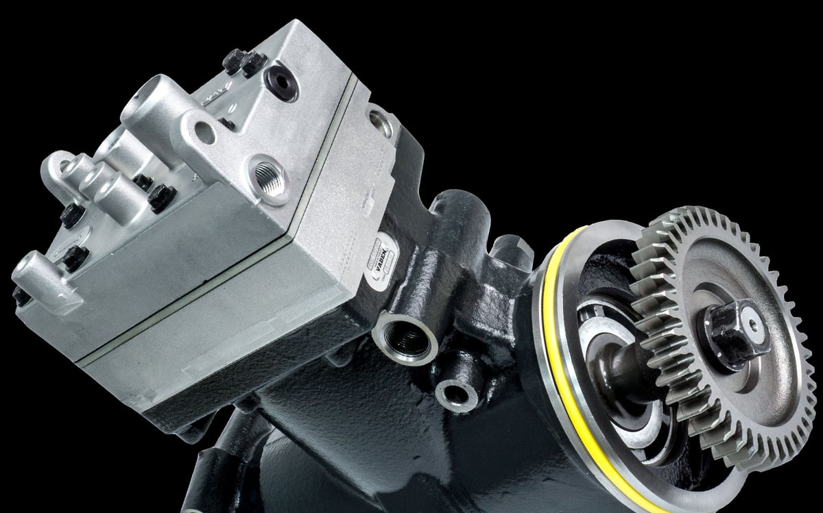
When a tractor unit comes into the shop with a note that simply says "compressor job", the thing that decides how long the work will actually take is usually not the compressor itself. The same job on two trucks of the same class can be a short reach under the hood on one and, on the other, a plan that requires half a dozen surrounding components to come off in sequence. Two variables produce that difference: which family the engine belongs to, and which chassis architecture that engine was installed in. This page deals with exactly those two variables. It does not explain what a compressor is, how it fails or how it is replaced; it explains where it sits on a given engine and how much work it takes to get there.
One sentence is enough for the definition: the air brake compressor is the unit driven by the engine that produces the compressed air the braking and auxiliary circuits need. Its duty, operating principle, failure symptoms, replacement procedure and maintenance discipline are covered in detail on the Air Brake Compressor: Faults, Replacement & Maintenance Guide page and are not repeated here. The subject of this page is narrower and more practical: how the engine family and the chassis make together determine the physical location of the compressor and the workload involved in reaching it, and where the North American platforms of Detroit, Cummins, PACCAR, Mack and International diverge from one another in that respect.
What engine family and chassis make determine about the compressor, and what they do not
The shortcut most often taken in the field is to ask "which truck brand". Yet the first layer that determines the physical arrangement of the compressor is not the chassis make but the engine family. The compressor bolts to the engine block, takes its drive from the engine's own motion train, and in most heavy-duty applications draws its cooling and lubrication connections from the engine's circuits as well. All of those are engine architecture decisions. An engine family largely fixes which end of the engine the drive comes from, the geometry of the mounting face the compressor sits on, which components are packaged around it, and whether a cooling connection exists at all.
The second layer is the chassis make, and it determines not the location but the access. When the same engine family is fitted to two different chassis, the compressor stays in the same zone on the engine; what changes is the world around that zone. Cab type, hood opening, front axle position, the depth of the cooling package, the routing of air and fuel lines, the placement of the starter motor and the aftertreatment unit, the volume the body occupies on the frame: all of these are chassis decisions, and they determine from which direction and through how many components the technician reaches the compressor.
This distinction produces a practical result. The engine family determines the nature of the job, the chassis make determines its duration. A family whose packaging places the compressor at the rear of the engine will not offer front access on any chassis; but the same family in a North American conventional tractor and in a European cab-over tractor will finish the same job in very different times.
What these two layers do not determine matters as much as what they do. Engine family and chassis make say nothing about whether the compressor is faulty. If pressure builds slowly on a vehicle, the cause may lie on the production side or on the loss side of the system; that separation is made by measurement, and it is the subject of the Air Compressor No Air or Pumping Oil: Diagnostic Guide. This page does not diagnose, does not list symptoms and does not describe replacement steps.
In the same way, knowing the engine family does not on its own produce a part decision. Reasoning of the form "the engine is from this family, therefore the compressor is this one" is not reliable on heavy commercial vehicles: within a single engine family there are different specification levels, different air demands and different connection variants. Identifying the correct part is a matching exercise carried out through an authorised catalogue using the engine and chassis identity of the vehicle; this page performs no such matching and gives no part numbers.
North American and European platforms: two different approaches to the compressor
In the heavy commercial vehicle world, the biggest line separating attitudes to the compressor is drawn less by the engine than by the cab architecture. North America's dominant layout is the conventional, that is the bonneted chassis: the engine sits ahead of the cab, under a long hood. Europe's dominant layout is the tilt cab; the engine sits beneath the cab and the cab is tilted forward for service. These two architectures do not change where the compressor sits on the engine, but they completely change how it is reached.
On a conventional chassis, opening the hood exposes the front face of the engine and part of its upper area. The rear of the engine, however, lies close to the cab firewall and outside the opening the hood provides. That is why, on North American platforms, a component packaged at the rear of the engine is usually serviced by approaching from the side, from underneath or through the space behind the wheel. The width of the hood opening, the position of the front axle relative to the engine and the depth of the cooling package decide how comfortable that approach will be; even between two conventional chassis carrying the same engine, if those three dimensions differ, the workload comes out differently.
On a tilt cab chassis, the moment the cab is tilted the top and both sides of the engine open up completely. The direction of access is different from the outset: the technician looks down on the engine. The price is the preparation before tilting and the working height once the cab is over; the gain is that almost the entire engine becomes reachable in a single move. For the same component, where a North American conventional chassis requires several neighbouring parts to come off, a tilt cab chassis usually allows a direct approach.
The second difference between the two regions is the density of air consumers around the compressor. On a North American long-haul tractor, the trailer air line, air suspension, cab suspension and auxiliary equipment all connect to a single source; on vocational vehicles, body circuits are added on top. In Europe the same functions are gathered into a more tightly packaged volume beneath the cab. This does not change the duty of the compressor, but it does change the number of lines around it, and therefore the number of connections that must be parted during access.
The third difference is the maintenance habit that follows from the architecture. On a conventional chassis the daily check is made from under the hood and the rear of the engine stays outside routine sight; on a tilt cab, every time the cab goes over the whole engine is seen. This is not a design fault but a natural consequence of the architecture, and it is accounted for in service planning.
Common drive and cooling arrangements by engine family: which platform shows which?
This section is not a concept section. What the terms drive interface and cooling architecture mean, the criteria by which they are assessed and all the factors that determine fitment are defined in the Single vs Twin-Cylinder Air Compressor: Choice & Fitment guide. The work done here is only mapping: which arrangement is commonly seen on which platform.
In heavy-duty tractor and vocational applications, the general tendency is for the compressor to take its drive from the engine's own gear train. Gear drive carries a higher continuous load than a belt and is independent of belt tension; given the continuity of heavy-duty air demand, that is why it is the common choice. Belt drive is seen less on heavy-duty tractors and more on medium-duty vehicles, some buses and special applications.
A similar tendency exists on the cooling side. In heavy-duty applications with high and continuous air demand, connecting the compressor to the engine coolant circuit is common; this arrangement allows the heat released during compression to be rejected through the engine cooling system and limits the air temperature at the compressor outlet. In lower-demand applications, air cooling can be sufficient. The presence of a cooling connection is an important detail from a service point of view: if the connection exists, the job may require the relevant part of the cooling circuit to be drained, and that directly extends the duration.
The table below summarises the general tendencies encountered on heavy-duty platforms. No row in the table is a verified configuration statement for a specific vehicle; within an engine family the model year, emissions level, market and specification option can change the arrangement.
| Engine family | Common drive arrangement | Common cooling approach | Typical zone on the engine | Main factor governing access |
|---|---|---|---|---|
| Detroit DD13, DD15, DD16 | Driven from the engine gear train | Usually engine coolant in heavy-duty use | Rear of the engine, close to the cab firewall | Hood opening not reaching the rear zone |
| Cummins ISX and X15 | Driven from the engine gear train | Usually engine coolant in heavy-duty use | Rear of the engine | Density of surrounding lines and working angle |
| PACCAR MX-11 and MX-13 | Driven from the engine gear train | Usually engine coolant in heavy-duty use | Rear of the engine | Hood and front axle package by chassis make |
| Mack MP7, MP8, MP10 | Driven from the engine gear train | Usually engine coolant in heavy-duty use | Rear of the engine | Vocational body and frame-mounted equipment |
| European heavy-duty families (general) | Driven from the engine gear train | Usually engine coolant in heavy-duty use | A side face or the rear of the engine | Working height once the cab is tilted |
| Medium-duty and special applications | Belt drive is seen more often | Air cooling is seen more often | Front or side of the engine | Position of the belt run and tensioner layout |
Only one general conclusion should be drawn from the table: on heavy-duty North American engines, the common arrangement is a gear-driven, water-cooled compressor positioned at the rear of the engine. For the technician, that means the "open the hood and look" scenario is largely invalid; the remaining sections of this page deal with what that conclusion means platform by platform.
Detroit DD13, DD15 and DD16: where the compressor sits on the engine
Detroit's heavy-duty DD family builds three displacement steps on a shared architecture. The DD13 is aimed at distribution and regional haul, the DD15 at the long-haul tractor application, and the DD16 at heavy-haul and vocational work. What these three engines have in common from the compressor's point of view is that the drive and packaging logic is consistent across the family: the compressor takes its drive from the engine's own gear train and sits at the rear of the engine, in a position close to the cab firewall.
This packaging has two service consequences. First, opening the hood does not make the compressor visible. On a North American conventional tractor, the hood opening covers the front and middle of the engine; the rear zone stays in the narrow volume between the engine and the cab. Second, the compressor is not alone in that zone: the starter motor, the exhaust manifold and turbocharger outlet, aftertreatment connections, fuel and coolant lines all share the same space. That density extends the "getting to the job" part far more than the job itself.
As displacement grows within the family, package density grows with it. An approach angle that is relatively comfortable on a DD13 can narrow on the DD15 and especially on the DD16; as the block grows, the clearance between the engine and the frame rail and the cab firewall shrinks. So for three members of the same family, the nature of the job is the same while its duration differs.
The cooling connection is the factor that most directly affects planning on this family. If the compressor is connected to the engine coolant circuit, working on the component may require the relevant section of that circuit to be drained, which adds preparation, plus refilling and bleeding, to the job list. Which arrangement a given vehicle has must be verified from current service documentation matching the engine identity.
Cummins ISX and X15: compressor layout in a high air demand tractor application
Cummins' heavy-duty ISX family and its successor the X15 are among the most widely fitted engine options in the North American long-haul tractor, and have been offered as a factory option across many different chassis makes. From the compressor's point of view, the defining characteristic of this family is that the drive is taken from the engine gear train and the compressor is positioned at the rear of the engine. In that respect the packaging logic resembles the DD family; the difference shows up in the arrangement of the surrounding components and in the chassis-side packaging.
The long-haul tractor application is a form of use that increases the number of lines around the compressor. Trailer air supply, air suspension, cab suspension, the park brake circuit and auxiliary equipment all connect to the same source. That does not change where the compressor sits; but it does increase the number of connections that must be parted to reach the component and the line routing that must be restored afterwards. Marking those connections in advance during service planning is a habit that noticeably shortens the total duration of the job.
The second consequence of high air demand is the thermal environment. In a zone where exhaust-side components sit around the compressor, the heat of a continuously working compressor is added on top. That produces a practical warning about approaching the component: this zone is not worked on while the engine is hot, and cool-down time is built into the job plan. The effect of air demand on the working load of the compressor is a separate subject and falls outside the scope of this page.
The differences between the ISX and the X15 lie largely at the level of emissions hardware, electronic control and auxiliary systems. In terms of compressor packaging the logic of the two families stays similar; however, as model years advance, the volume aftertreatment components occupy on the chassis and the routing of lines close to the engine change, so the access path can differ by year even within the same engine family.
PACCAR MX-11 and MX-13: what changes between Kenworth and Peterbilt chassis?
The PACCAR MX family is the clearest illustration of this page's central argument: same engine, different chassis. The MX-11 and MX-13 are offered as the same engine family in the two North American chassis makes under the PACCAR roof, Kenworth and Peterbilt. The engine's own architecture, and therefore the drive arrangement and the zone the compressor occupies on the engine, follow the same logic in both makes. What changes is entirely on the chassis side.
Another characteristic of the MX family is that its architecture is related to the European heavy-duty engine tradition; it descends from a shared design lineage with the DAF engine family of the same name. That creates an interesting situation: an engine architecture of European origin has been installed in North America's conventional bonneted chassis. While the engine's own layout stays close to European habit, the access arrangement is entirely governed by North American architecture. The comfortable access the same engine offers under a European tilt cab does not apply on a conventional chassis. Here too, knowing the engine family gives you the location, not the access.
From a compressor point of view, the differences between Kenworth and Peterbilt gather under these headings: how the hood opens and how much of the engine the opening exposes, the position of the front axle relative to the engine, the depth of the radiator and cooling package, the clearance between the cab firewall and the engine, the possibility of a side approach through the space behind the wheel, and the choice of line routings. These dimensions vary from make to make and from model series to model series, which is why no generalisation of the form "a compressor job on an MX-13 takes this long" can be made. The correct statement is this: on an MX-13 the nature of the job is defined, while its duration depends on the chassis.
Standards and further reading
This subject is governed by the equipment rules for air-braked commercial vehicles. In the United States the federal air brake standard, FMVSS 121 (49 CFR 571.121) defines the reservoirs, protection and timing a compliant system must provide, and Europe applies the equivalent limits of UNECE Regulation No. 13. For further detail, see the illustrated reference guide at airbrakecompressor.com. Always confirm specific figures against the current regulation and the vehicle manufacturer service data.
Readers outside the United States should work from their own national framework: in the United Kingdom the braking system must be maintained under regulation 18 of the Road Vehicles (Construction and Use) Regulations 1986, and in India the governing rules are published by the Ministry of Road Transport and Highways.
Mack MP7, MP8 and MP10: how vocational use shows up at the compressor
Mack's MP family shares its heavy-duty architecture with the Volvo heavy-duty engine tradition and is widespread in North America especially in vocational use: dump, mixer, refuse collection, tractor and heavy haulage. On the engine side, the compressor logic resembles the other heavy-duty families; the drive is taken from the engine gear train and the compressor is positioned at the rear of the engine. What makes the difference in this family is not the engine but the form of use.
On a vocational vehicle the chassis is not an empty carrier. The body, the lifting arrangement, power take-off connections, additional air reservoirs, and the air and hydraulic lines running to the body all occupy space on the frame and around the engine. A side or underneath approach to the compressor that may be open on a long-haul tractor can be closed on a mixer carrying the same engine. At this point the factor governing access moves from the engine family to the body installation.
The second difference is the working environment. In uses such as construction sites, quarries and waste collection, dust, mud and salt accumulate in the engine bay; cleaning is required before the component can be reached. Adding that step to the access plan does not change the nature of the job, but it makes the duration realistic.
The third difference is that the usage profile of the vehicle increases the number of lines around the compressor. On vehicles with a body air circuit, the number of consumers fed from the compressor is higher and the connection routings pass through the engine bay. That increases both the number of connections to be parted during access and the number of points to be verified after the job. The displacement difference between the MP7, MP8 and MP10 produces a result similar to the DD family: as the engine grows, the clearance around it shrinks and the approach angle narrows.
International chassis with Detroit engines: same engine, different packaging
A distinguishing feature of the North American heavy commercial vehicle market is that the engine and chassis decisions can be made independently of one another. A buyer can select the chassis make from one manufacturer while choosing the engine from a separate list. This is a flexibility less often seen in Europe, and it bears directly on the subject of this page: the same engine family appears with different access arrangements on different chassis makes.
International chassis are a typical example of that flexibility. When an engine family is used together with a different chassis make's hood geometry, front axle position, cooling package and firewall distance, the position of the compressor on the engine does not change but the route to it does. A habit a technician has formed on one chassis make, along the lines of "remove that panel, approach from that side", can lose its validity on the same engine in another chassis. Location is learned from the engine, access from the chassis; when the two are confused, the result is a wrong time estimate.
One point deserves attention here: which engine families a chassis make offers as a factory option varies by model year, series and market. Those lists are updated over time; commercial partnerships change and emissions regulations reshape the options. That is why the engine family of a specific vehicle is established from the vehicle's own identity data, not from a remembered brand pairing. This page gives no list of which chassis make was sold with which engine; the only rule it offers is this: verify the engine family from the vehicle, and build the access plan according to the chassis series.
The practical application is simple. At job intake, two pieces of information are recorded separately: the engine family and the chassis series. The engine family determines the nature of the job, the chassis series determines its route. In workshops where both are recorded together, the time estimate becomes accurate when the same job comes back; in workshops where only the brand name is recorded, every vehicle is discovered from scratch.
A brief look at European engines: Mercedes-Benz, MAN, Scania, Volvo, DAF and Iveco
On European heavy-duty engine families as well, the compressor is a component driven from the engine gear train and, in heavy use, generally cooled by engine coolant; the packaging logic belongs to the same family as North American heavy duty. The difference emerges not in the engine but in the cab: because the tilt cab architecture opens the top and both sides of the engine in a single move, access to the compressor on Mercedes-Benz, MAN, Scania, Volvo, DAF and Iveco heavy-duty vehicles is generally a more direct operation than on North American conventional chassis. Packaging, drive arrangement and service details for each of these engine families are covered separately on our related engine pages; this section only builds the bridge, and the focus of the page stays on the North American platforms.
Access to the compressor: packaging differences that change service time by engine family
Access workload is made up of too many variables to reduce to a single number; but those variables can be counted. In practice, the factors that determine the duration of a compressor job gather under six headings, and all of them relate to packaging: approach direction, the number of neighbouring components that must come off, whether the cooling circuit is touched, connection density, working angle, and the need for lifting or supporting.
Approach direction determines which zone of the engine is worked on. A component positioned at the front or side of the engine can be reached from under the hood, while a component at the rear requires an approach from the side, from underneath or through the space behind the wheel. The number of neighbouring components counts the obstacles in the way of that approach; as the engine bay gets denser, that number rises. The cooling circuit is the item that adds the most time: if a connection exists, preparation, draining, refilling and bleeding steps join the list.
Connection density rises with the number of consumers fed from the compressor and reaches its highest value on vocational vehicles. Working angle expresses the angle at which the technician's hand and tool reach the component; tight angles increase both the time and the risk of error. The need for lifting and supporting arises from the weight and position of the component; there is a clear difference in this respect between a position reached from above and one reached from below.
Establishing the packaging before a job starts is the cheapest step that brings the estimated time closer to reality. The sequence below is not a removal procedure but a planning sequence:
- Record the vehicle and engine identity. The chassis make and series and the engine family are written separately; either one alone is not enough to build the plan for the job.
- Verify which end of the engine the drive comes from. Whether the gear train sits at the front or the rear of the engine sets the approach direction from the start.
- Check whether a cooling connection exists. If it does, cooling circuit preparation and completion items join the job list; if not, that item drops out entirely.
- Count the surrounding components. Every component on the access path is assessed individually for whether it will be removed or merely loosened.
- Mark the connection routings. When the lines and electrical connections to be parted are marked beforehand, the reassembly stage gets shorter and the risk of a wrong connection falls.
- Choose the access direction and the equipment needed. The decision to approach from above, from the side or from underneath, together with lifting, supporting and lighting needs, is settled at this step.
- Write the time estimate, and record the actual time when the job is done. When the same engine and chassis combination comes back, the estimate is made from that record.
The most valuable output of this sequence is the last item. A time record in which the engine family and the chassis series are logged together gives the workshop its own platform table after a handful of jobs; that table ends up more accurate than any general guide could be, because it was produced from that fleet's own vehicles.
| Chassis architecture | Typical access route | Most common obstacle | Qualitative workload tendency |
|---|---|---|---|
| Conventional bonneted tractor (North America) | Limited under the hood; approach from the side and behind the wheel | Rear of the engine falling outside the hood opening | Medium to high |
| Conventional bonneted vocational vehicle | From below and from the side; varies with the body | Body, extra reservoirs and line routings blocking the path | High |
| Tilt cab tractor (Europe) | Directly from above once the cab is tilted | Cab tilt preparation and working height | Low to medium |
| Tilt cab vocational vehicle | From above; varies with body connections | Body circuits passing through the engine bay | Medium |
| Bus and special chassis | Through a service hatch or the rear compartment | Packaging density inside the compartment and access angle | Varies with chassis design |
The qualitative workload column in the table is deliberately comparative rather than numerical. How many hours a job takes depends on the age of the vehicle, the state of accumulated deposits, the quality of previous interventions, the equipment of the workshop and the technician's experience on that platform. The only reliable measure given on this page is how the architectures rank relative to one another for the same job.
A final reminder: packaging knowledge is not a part decision. Knowing where the compressor sits on the engine does not tell you which product to fit. VADEN ORIGINAL manufactures OE-equivalent compressors and spare parts for heavy commercial vehicle air brake systems; identifying the correct product, however, is a matching exercise carried out through an authorised catalogue using the engine and chassis identity of the vehicle, and it falls outside the scope of this page.
How these two displacement classes are chosen against the duty profile, and how fitment is verified, is taken apart in the single vs twin-cylinder compressor guide.
Shop this part: Air Compressor
Which questions reveal a supplier's manufacturing depth and consistency over time is examined from a purchasing angle in choosing an air brake compressor manufacturer.
Main guide: Air Brake Compressor: Faults, Replacement & Maintenance Guide
Tags
Frequently Asked Questions
- Can a compressor be selected from the information on the engine label?
- No. The engine label gives the engine family and the engine's identity data; it does not tell you which compressor variant is fitted. Within the same engine family there can be different specification levels, different air demands and different connection arrangements, and these cannot be read from the label alone. Identifying the correct part is a matching exercise carried out through an authorised catalogue and service records using the engine and chassis identity of the vehicle. This page explains packaging and access; it does not perform part matching.
- How do I work out where the compressor sits on the engine before the job starts?
- Two pieces of information are enough: the engine family, and which end of the engine the gear train is on. On heavy-duty North American engines, the common arrangement is for the drive to be taken from the gear train at the rear of the engine and for the compressor to be positioned in that zone. The exact position is verified from current service documentation matching the engine and chassis code of the vehicle; model year and specification option can change the arrangement.
- Does the same engine family sit in the same place on every chassis?
- Its position on the engine stays largely the same, because that is an engine architecture decision. What changes is the access. When the same engine family is fitted to a chassis with a different hood geometry, a different front axle position and a different cooling package, the neighbouring components that must come off and the approach direction to reach the same part can change. That is why the packaging is learned from the engine and the access plan from the chassis.
- What is the most noticeable difference between North American and European platforms?
- The difference is not on the engine side but in the cab architecture. North America's dominant layout is the conventional bonneted chassis; the hood opening does not reach the rear of the engine and that zone is approached from the side or from below. Europe's dominant layout is the tilt cab; when the cab goes over, the top and sides of the engine open in a single move. The position of the compressor on the engine is determined by similar logic in both architectures; what differs is the route to it.
- Does the answer to the single or twin-cylinder question change with the engine family?
- That is not a packaging question but a capacity and fitment question, and it falls outside the scope of this page. The number of cylinders is determined by assessing the total air demand of the vehicle together with the drive and cooling arrangement; it is not chosen by looking at the engine brand alone. All the criteria and the comparison are covered in the Single vs Twin-Cylinder Air Compressor: Choice & Fitment guide.
- Does the cab always have to be raised to reach the compressor?
- No, that depends entirely on the chassis architecture. On tilt cab vehicles the cab is tilted and the top of the engine is reached directly, which is usually the shortest route. On conventional bonneted vehicles the cab is not tilted; access is gained from under the hood, from the side, through the space behind the wheel or from underneath. Which route is chosen is planned before the job starts, according to the zone of the engine and the packaging of the components around it.
- Why does packaging create more work on a vocational vehicle?
- The engine side does not change, but the chassis side gets crowded. The body, the lifting arrangement, extra air reservoirs and the air and hydraulic lines running to the body occupy space around the engine and on the frame; a side or underneath approach that is open on a tractor can be closed on these vehicles. Added to that is the dust and mud accumulation brought by uses such as construction sites and waste collection; cleaning is needed before the component can be reached, and that adds time to the job plan.
- How does the compressor's cooling connection affect job time?
- In heavy-duty applications, connecting the compressor to the engine coolant circuit is common. That connection links work on the component to the relevant section of the cooling circuit; preparation, draining, refilling and bleeding items join the job list and the total duration grows. On air-cooled arrangements that item drops out entirely. Which arrangement a given vehicle has must be verified from current service documentation matching the engine identity.
- If the vehicle is not building air, should you go straight to the compressor?
- No. Pressure building slowly or not at all does not on its own point to the compressor; the source may lie on the production side or on the loss side of the system. That separation is made by measurement and is the subject of a separate diagnostic flow. Packaging knowledge comes into play only after the diagnosis is complete and the decision to intervene has been made; the function of this page is exactly that stage, planning the route and the duration of the job.
- Is the packaging information on this page valid for every model year?
- No, the statements given here describe common tendencies. Within an engine family, the model year, emissions level, market and specification option can change the position of the compressor, the arrangement of the components around it and the access route. Before any work is carried out on a vehicle, consulting the current manufacturer service manual matching the engine and chassis code of that vehicle is essential.
Related Articles
Clutched Air Brake Compressor: Faults, Replacement, Care
Clutched air brake compressors on trucks: how the clutch works, telling a slipping clutch from a worn compressor, replacement steps and torque values.
Single vs Twin-Cylinder Air Compressor: Choice & Fitment
Learn how to match single or twin-cylinder air brake compressors to your truck: flow demand, drive and cooling interfaces, fault diagnosis, replacement steps.
Air Brake Compressor: Faults, Replacement & Maintenance Guide
On a truck, a slow-filling reservoir or oil in the dryer often starts at the compressor's cut-in/cut-out cycle, not the compressor body: diagnosis and care.


