Air Brake Fault Diagnosis: Symptom, Cause, and Solution Guide
A field guide to diagnosing air brake faults in heavy trucks: symptom-cause tables, pressure test points, leak hunting, and a step-by-step troubleshooting order.
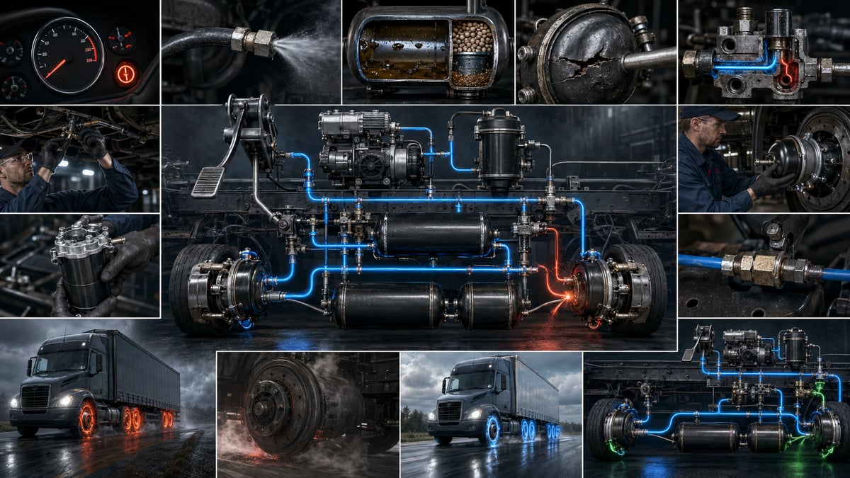
A loaded tractor is slow off the mark on the first pull of the morning: the gauge climbs sluggishly toward working pressure, the dryer purges every couple of minutes, and releasing the park brake produces a hiss that lasts far longer than usual. The driver's diagnosis is ready before the bonnet is even up — "it's not holding air" — and the finger almost always points at the compressor. Yet the same symptom can hide at least five genuinely different causes, and the compressor is only one of them. That is the whole difficulty of air brake diagnosis: the system shows the fault where it is most visible, not where it started. This guide builds the route from symptom back to cause in an order that can actually be followed on the shop floor.
Before you start diagnosing: safety, stored energy, and asking the right question
The air brake system carries stored energy even while it is being diagnosed. As long as the reservoirs are charged, every line is under pressure; once they are empty, the spring force inside the spring brake chambers takes over instead, and that force never simply disappears. So diagnosis begins before any gauge is connected, by making the vehicle safe: level, solid ground, engine off, wheels chocked, cab locked. Chocks are not a substitute for the park brake — during diagnosis the park brake will deliberately be released, and at that moment the chocks are the only thing holding the vehicle.
The second preparation, just as important as safety, is getting an accurate description of the symptom. A driver's "the brakes aren't holding" can point to five entirely separate faults once the vehicle is on the ramp. A short set of questions asked at hand-over shortens the whole diagnosis:
- When does it appear? Only on the first pull of the morning, on a long haul, going downhill, or all the time?
- Loaded or empty? A symptom that only shows up loaded points toward the load-sensing side and the slack adjusters.
- With or without a trailer? If behaviour changes between coupled and uncoupled, the fault sits at the coupling heads and the trailer line.
- Worse in the cold? A symptom that grows only in cold weather almost always points to moisture and freezing in the system.
- What does the dash say? Is the low-pressure warning, ABS, or EBS lamp on continuously, or only at a particular moment while driving?
Mapping the air brake system through a diagnostic lens
Diagnosis gets easier once the system is seen as a chain of zones rather than a parts list. Finding which zone a symptom originates in matters more than finding the exact part inside that zone.
| Zone | Main components | Symptom pointing to this zone |
|---|---|---|
| Supply | Compressor, drive belt or gear, cooling and lubrication connections | Longer charge time, oil in the reservoirs, overheating |
| Conditioning | Pressure governor, air dryer and cartridge, safety valve, oil separator | Continuous purging, water in the reservoir, cut-out pressure drifting |
| Storage and distribution | Wet tank, circuit reservoirs, four-circuit protection valve, pipes and hoses | Fast pressure loss once the engine stops, one circuit not charging |
| Control | Foot brake valve, hand control valve, relay valves, ALB load-sensing valve, EBS modulators | Late apply, late release, imbalance between axles |
| Application | Brake chambers, spring brake, brake lever and automatic slack adjuster, camshaft, lining, drum or disc | One wheel overheating, pulling to one side, dragging |
| Trailer interface | Red and yellow coupling heads, trailer parking valve, trailer relay and emergency valve, trailer reservoirs | Trailer not holding, releasing late, self-applying |
The critical feature of this map is that the influence runs one way. A defect on the supply or conditioning side produces symptoms in every zone downstream, whereas a leak at a single brake chamber only affects the compressor's behaviour indirectly. That is why diagnosis is always worked from the top down. For a full refresher on the system's working principle and component glossary, the air brake systems guide covers the logic behind this map in detail; this article reads the same system from the symptom side.
Symptom, probable cause, and where to look first
The table below matches the symptoms most often seen in the field with their likely causes, the first place to look, and the measurement that proves the diagnosis. The table does not make the call; it narrows the list of suspects. Causes are listed roughly in order of how often they occur.
| Symptom | Probable causes | Check first | Confirming measurement |
|---|---|---|---|
| Pressure never reaches working value | Major leak, compressor efficiency loss, governor cutting out early, dryer stuck purging | Dryer purge port, reservoir connections | Peak pressure and charge time at the wet tank |
| Pressure drops fast once the engine stops | Reservoir, pipe, fitting, or valve leak; dryer check valve leaking back | Reservoir drain cocks, fitting areas | Static leak test: engine off, brakes released |
| Pressure drops sharply when the pedal is pressed | Control-line leak, chamber diaphragm split, relay valve leak | Brake chambers, relay valve exhaust port | Dynamic leak test: pedal held down |
| Vehicle parked overnight is empty by morning | Slow leak, dryer purge valve leaking, parking valve leaking internally | Dryer purge port, trailer coupling heads | Extended hold test with a soapy-water sweep |
| Brake applies late | Foot valve response lag, relay valve opening late, stroke too long, line restriction | Relay valve, slack adjuster stroke | Time for pressure to rise at the chamber inlet |
| Brake releases late, wheel drags | Relay valve exhaust blocked, weak return spring, seized camshaft, frozen moisture | Relay valve exhaust port, camshaft bushings | Time for pressure to drop at the chamber after release |
| One wheel overheats | Seized camshaft, broken return spring, out-of-adjustment slack adjuster, spring brake not fully releasing | Brake lever and chamber at that wheel | Chamber pressure at rest and check that the lever returns |
| Park brake won't release | Insufficient pressure in the park circuit, park valve fault, internal seizure in the spring chamber, freezing | Park circuit supply pressure | Pressure measurement at the spring chamber's park side |
| Trailer not holding or slow to hold | Yellow-line leak, coupling head seal, trailer relay valve, trailer load-sensing adjustment | Yellow coupling head, trailer relay valve | Control pressure measurement at the trailer brake line |
| Dryer never purges, water in the reservoir | Purge valve blocked or frozen, cartridge at end of life, heater fault | Purge port, heater connection | Assessment of the liquid discharged at the reservoir drain |
| ABS or EBS lamp on, no mechanical symptom | Wheel-speed sensor gap, chafed wiring, modulator supply, low voltage | Sensor wiring route, connectors | Live data and fault code read-out with a diagnostic tool |
What stands out in the table is that the same cause can show up under several symptoms. A leaking dryer purge valve appears in four different rows at once — the morning-empty vehicle, the constant hiss, the longer charge time, and the fast pressure drop once the engine stops. That is why symptoms are read together rather than one at a time; the point where several symptoms overlap is usually the real address of the fault.
The order of diagnosis: narrowing the zone
The most common mistake is starting with the most likely part. The right method starts with the zone that is easiest to rule out, not the part that seems most likely. The system is split from the top down, and each step eliminates one zone with certainty.
First question: can the system build working pressure at all? If it cannot, the fault is in the supply or conditioning zone, or there is a major leak. If it can, the supply side is ruled out.
Second question: is the pressure it builds actually held? If pressure drops faster than acceptable once the engine is off and the brakes are released, the leak is on the storage and distribution side. If it only drops fast once the pedal is pressed, the leak is on the control and application side.
Third question: does the control pressure actually reach the chamber? If pressure measured at the chamber inlet rises and falls in step with pedal movement, the control zone is healthy and the fault lies on the mechanical side. If it rises or falls late, the control valves are the suspects.
Fourth question: can the mechanical side turn that pressure into motion? If braking is weak, or the wheel drags, while the pressure at the chamber is correct, the fault is in the lever, camshaft, slack adjuster, lining, or friction surface — and from here the measuring tool is no longer a gauge but a ruler and a trained eye.
Pressure measurement points and gauge verification
The dash gauge is not a diagnostic instrument. It shows the pressure of just two circuits, with limited resolution and its own error margin — it says nothing about what is happening at a chamber, at the park line, or at a trailer coupling. Serious diagnosis is done with calibrated pressure gauges connected to the service test points. Using two gauges at once, so the difference between them is seen directly, is worth far more than two separate readings taken one after the other with a single gauge.
- Park the vehicle on level ground, chock the wheels, switch off the engine, and make sure no one else is working nearby.
- Fit the gauges to the wet tank and circuit reservoir test points and confirm with soap solution that the connections themselves don't leak; a leaking gauge fitting can easily be mistaken for the fault you're chasing.
- Start the engine and charge the system from empty; note the peak value and how long it takes to reach it. Charge time is the most practical single indicator of the balance between compressor output and leakage.
- Record the exact moment the governor cuts out and the sound of the dryer purging, then bleed the reservoir down in a controlled way and read the value at which the system starts building pressure again. If the gap between these two values falls outside the band in the OE manual, the governor is the suspect.
- Switch off the engine, release the brakes, and watch the pressure over a set period; this static reading exposes leaks on the supply and storage side.
- Hold the pedal down and repeat the same period. If a system that looked fine at rest now loses pressure quickly, that proves the leak is on the control and application side.
- Move the gauges to the chamber inlet ports and take simultaneous readings at the left and right wheel of the same axle, then apply and release the pedal in stages while watching how pressure rises and falls.
- If a trailer is coupled, measure separately at the red supply and yellow control coupling heads; the difference between the tractor's output and the trailer's input reveals losses at the coupling and along the line.
- Log every reading in the vehicle file, cap the test points, and once the system is back at full pressure, confirm the result with a low-speed brake test in a safe area.
| Measurement point | What it reveals | Zone the deviation points to |
|---|---|---|
| Wet tank (first reservoir) | Actual pressure produced by the compressor and governor | Supply and conditioning zone |
| Front and rear circuit reservoirs | Whether the two brake circuits are supplied independently | Protection valve and circuit lines |
| Park (spring) circuit line | Whether enough pressure is present to release the park brake | Park valve and park line |
| Brake chamber inlet, front axle | The actual value reaching the chamber from the control side | Foot valve, lines, and the front relay arrangement |
| Brake chamber inlet, rear axle | Control pressure and load compensation delivered to the rear axle | Relay valve, ALB load sensing, EBS modulator |
| Trailer coupling heads (red and yellow) | Supply and control pressure reaching the trailer | Coupling head, trailer parking valve, trailer relay valve |
In heavy commercial vehicles, working pressure is usually kept within a band of roughly eight to twelve and a half bar; the cut-out value, the cut-in value, the allowed difference between circuits, and the acceptable leak rate all vary by vehicle and manufacturer. Every reading must be checked against the band given in the current OE service manual for that engine and chassis code — it is this comparison, not the reading on its own, that produces the diagnosis.
Low or slow-building pressure: compressor, dryer, leak, or valve?
Is it a leak? If pressure drops faster than normal once the engine is stopped, nothing on the charging side is actually to blame — the system is charging fine, it just can't hold what it charges. The size of the leak shows up in how often the dryer purges: if the compressor never gets a rest, the leak is serious. Close the leak first, then repeat the other measurements; judging the compressor while a leak is still present is misleading.
Is it the compressor? If the system isn't leaking but the charge time has clearly grown longer, the supply side comes into question. Before blaming the compressor, check what feeds it: a clogged air filter, a crushed intake hose, a loose or glazed drive belt, a leaking outlet fitting. Every one of these makes the compressor look inefficient without the compressor itself being at fault. If the outlet line runs unusually hot, suspect a restriction or back-pressure downstream of the compressor.
Is it the dryer? If the purge valve stays open, a large share of the air the compressor produces is simply dumped, and the symptom looks exactly like a weak compressor; the tell is a continuous hiss of air at the purge port rather than a short burst. If the check valve leaks back, air escapes through the dryer after the system has charged, and the vehicle is empty by the next morning.
Is it a valve? If the governor cuts out early, the system never reaches full pressure; if it cuts out late, the safety valve opens and the system keeps venting air. A fault in the four-circuit protection valve creates a stranger picture: one circuit charges normally while the other lags behind or never fills at all. A side-by-side reading at the circuit reservoirs uncovers this within a few minutes.
Standards and further reading
This subject is governed by the equipment rules for air-braked commercial vehicles. In the United States the federal air brake standard, FMVSS 121 (49 CFR 571.121) defines the reservoirs, protection and timing a compliant system must provide, and Europe applies the equivalent limits of UNECE Regulation No. 13. For further detail, see the illustrated reference guide at airbrakecompressor.com. Always confirm specific figures against the current regulation and the vehicle manufacturer service data.
Inspection practice differs by country. In the United Kingdom the defect definitions and the pass or fail criteria for heavy goods vehicles are set out in the DVSA HGV inspection manual; in South Africa the underlying instrument is the National Road Traffic Act 93 of 1996.
Leak hunting: method, order, and pass/fail criteria
The secret to leak hunting is not a sharp ear but a method. The right approach splits the system into logical sections and tests each one separately.
- Charge the system to full pressure and stop the engine; watch the gauge connected to the reservoir, not the one on the dash.
- With the brakes released, watch the pressure over a set period and record how much it drops. This is the leak test for the supply and storage side.
- Repeat the same period with the pedal held down; if the second figure is noticeably larger, the leak is on the control and application side.
- Release the park brake and take the measurement once more. A leak that only grows at this step points to the park line and the spring brake chambers.
- If a trailer is coupled, uncouple it and repeat the measurement; if the leak leaves with the trailer, the tractor side is clean.
- Within the zone you've narrowed it down to, sweep every point with soap solution: fittings, hose ends, valve body joints, and purge or exhaust ports, in that order.
- Treat valve exhaust ports as a category of their own; a continuous flow of air from a valve's exhaust port is the clearest possible sign that its internal seal has failed.
- Sweep the diaphragm area of each chamber both at rest and under application; a split diaphragm only reveals itself while the brake is applied.
- Fix every leak you find and repeat the measurement starting from step one. Stopping the search after finding a single leak is the most frequently repeated mistake in this diagnosis.
There is no single universal pass/fail figure; the allowable pressure drop depends on the number of circuits, reservoir volume, whether a trailer is coupled, and the time period set by the manufacturer. In practice, two observations are reliable guides: a system losing most of its working pressure overnight is always abnormal, and a compressor that never gets a rest while the engine is running is always abnormal too.
Slow to apply vs. slow to release
In driver language, "the brakes aren't responding" covers two technically unrelated faults. Slow to apply means braking force builds up late after the pedal is pressed; slow to release means the brake stays applied for a while after the pedal is let go. The first extends stopping distance; the second burns out linings and drums, raises fuel consumption, and causes heat-related loss of performance on long descents.
| Criterion | Slow to apply | Slow to release |
|---|---|---|
| What the gauge shows | Chamber pressure rises slowly | Chamber pressure drops slowly or never reaches zero |
| Pneumatic causes | Foot valve response lag, relay valve opening late, line restriction, insufficient supply | Relay valve exhaust blocked, internal valve seizure, moisture frozen in the line |
| Mechanical causes | Excessive stroke, out-of-adjustment automatic slack adjuster, excessive lining clearance | Broken or fatigued return spring, seized camshaft, dry or worn bushings |
| Heat behaviour | The brake area does not noticeably heat up | Drum or disc stays hot continuously, with odour and blistered paint |
| Relationship to cold | Does not change noticeably with temperature | Increases markedly in cold weather, frozen moisture a strong suspect |
| Distinguishing test | Time for pressure to rise at the chamber after application | Time for pressure to drop at the chamber after release |
What both faults share is that a single pressure reading at the chamber inlet can separate a pneumatic cause from a mechanical one. If pressure at the chamber inlet rises and falls within the normal time and the symptom still persists, the fault is definitely mechanical, and replacing pneumatic parts will change nothing. For the chamber's internal condition, diaphragm health, stroke measurement, and mounting rules, the brake chamber guide gives a detailed inspection procedure; stroke measurement is the shared confirmation tool for both faults.
One wheel overheating and pulling to one side
A single wheel running noticeably hotter than the rest almost always means that wheel's brake is not fully releasing. The temperature difference should be judged with a non-contact thermometer comparing the two wheels of the same axle, not by hand — a hand check is both unsafe and unreliable.
Diagnosis proceeds by finding why the brake won't release. The first possibility is pneumatic: if pressure is still present at the chamber with the brake released, a valve on the control side isn't exhausting the air, and the fault sits in the line feeding that wheel rather than at the wheel itself. The second is mechanical: if the lever won't return even with no pressure at the chamber, the problem is in the camshaft, return spring, slack adjuster, or brake mechanism. A single gauge reading is all it takes to tell these two apart.
Pulling to one side comes from a difference in braking force between the two wheels of the same axle. If the comparative reading shows equal pressure on both sides, the difference is mechanical and frictional: mismatched lining sets, oil or grease contamination, a surface glazed by heat, or a geometry fault in the drum or disc. If the reading shows different pressure, the fault is pneumatic, and that side's line, relay valve, or modulator comes into question.
Trailer not holding, slow to hold, or self-applying
Trailer brake complaints need a logic of their own — there are two coupling heads, two separate lines, and the trailer's own valve arrangement in between. The first step is always the same: establish whether the symptom travels with the trailer or with the tractor. If it disappears when a different trailer is coupled, the fault is on the trailer; if it follows the tractor, the fault is on the tractor side.
If the trailer doesn't hold at all, or holds weakly, the first step is to measure the pressure arriving at the yellow control line. If it is correct at the coupling head outlet but low at the trailer's inlet, the fault is at the coupling and its seal. If both points read correctly, the trailer relay valve, the load-sensing arrangement, and the trailer's mechanical side come into question; a trailer that only holds weakly when empty usually means the load-sensing setting has drifted.
If the trailer is slow to hold, the control signal is arriving late: long or narrowed lines, a clogged coupling filter, a malfunctioning trailer relay valve, and frozen moisture are the leading causes. A tractor that brakes while the trailer lags behind creates a pushing force in the middle of the combination that is especially dangerous on a slippery surface; this complaint is never left for later.
If the trailer self-applies, diagnosis focuses on the red supply line. The trailer's emergency system is designed by nature to apply the brakes once supply pressure falls below a set value, so a self-applying trailer is often the system responding correctly rather than failing. What actually needs to be found is what's dropping the supply pressure: a leaking coupling head, a crushed hose, the position of the trailer parking valve, or a supply restriction on the tractor side.
Park brake won't release or won't hold
The park brake holds through a mechanical spring inside the spring chamber and releases with air pressure — this reversed logic produces two separate fault types. If it won't release, measure the pressure arriving at the park circuit first. If the system hasn't reached working pressure, the park brake was never going to release; that is not a park brake fault but a supply fault, and diagnosis goes back to the supply side. If pressure is present in the park line but doesn't reach the spring chamber's park side, suspect the park control valve, the line, or the quick-release valve. If pressure does reach the chamber but the spring won't release, the fault is inside the chamber itself: internal seizure, corrosion, a deformed piston, or frozen moisture. A park brake that only refuses to release on winter mornings points almost every time to frozen moisture in the line.
If it won't hold, diagnosis shifts to the mechanical side. The most dangerous cause is a manual release bolt tightened during an earlier job and never backed off again — in that state the park brake is physically disabled and nothing about it looks wrong from the outside. The second cause is excessive stroke combined with worn linings; even with the same spring force, the mechanism can't convert it into braking force. The third is the spring itself losing force. Park brake condition cannot be judged by eye; a controlled hold test on a safe gradient plus a stroke measurement is the only valid assessment.
Compressor pumping oil and dryer not doing its job
Oil showing up in the reservoirs is usually blamed on the compressor outright, yet at least three scenarios sit behind this symptom. The first is genuine oil carry-over: once the rings and cylinder bore wear, some crankcase oil mixes into the air being pumped; the tell is dark, oily liquid at the wet tank drain, the cartridge saturating before its time, and a persistent oil film in the lines. The second is overheating: a compressor run under heavy load for long periods condenses oil vapour further down the line; the underlying cause is very often a leak in the system, because a compressor that never gets a rest never gets a chance to cool either, and a brand-new replacement compressor will meet the same fate. The third is oil mixing with water: when the dryer isn't doing its job, the moisture it collects emulsifies with a small amount of oil and a milky liquid comes out at the drain. The colour of that liquid is the first clue: clear water suggests a moisture problem, dark oil suggests the compressor, and a pale emulsion suggests both at once.
The order of verification is fixed. Leaks are closed first and the compressor's duty cycle is brought back to normal; the reservoirs are then fully drained and cleaned, and after a set running period the discharged liquid is assessed again. The intake line, air filter, and cooling and lubrication connections are checked; a blocked oil-return line can make a perfectly healthy compressor look like it's pumping oil. If oil is still present after these steps, a repair or replacement decision can be made on the compressor — and at that point the contaminated cartridge, lines, and reservoirs must be dealt with too, otherwise the new compressor is simply installed into the old contamination.
On the dryer side, there are two abnormal extremes. With continuous purging, it must first be established whether the purge is genuinely non-stop or just very frequent; very frequent purging is usually caused by a leak elsewhere, while a truly continuous purge points to the purge valve staying open or a fault on the governor side. With no purging at all, moisture builds up fast and the symptoms cascade: water at the reservoir drain, valves freezing in winter, the park brake not releasing in the morning, internal corrosion, and valves sticking. Cartridge life depends on the volume of air passed through it, not on mileage; in a leaking system the compressor works far harder and the cartridge saturates much sooner, which is why replacing the cartridge alone is never the full fix. For dryer diagnosis, the cartridge replacement procedure, and winter behaviour, the air dryer guide gives a detailed inspection sequence.
Reading ECU fault codes together with the mechanical symptom
On vehicles fitted with EBS and ABS, a diagnostic tool is indispensable, but never sufficient on its own. A stored code describes an inconsistency the electronics detected; it says nothing about what the brake is physically doing.
| Code group | What the electronics see | Mechanical evidence to check at the same time | What they mean together |
|---|---|---|---|
| Wheel speed sensor | Signal dropout or inconsistency between wheels | Sensor air gap, chafed wiring, hub bearing play, dirty tone ring | If wiring and air gap are sound, the hub side comes into question |
| Modulator or valve circuit | Coil resistance, short circuit, or open circuit | Connector corrosion, water ingress, chassis ground | If there's no electrical evidence, the valve itself is the suspect |
| Supply voltage | Low or fluctuating voltage | Battery, charging system, cable gauge, loose earth point | Numerous codes across independent circuits point first to the supply |
| Pressure sensor | A gap between expected and measured pressure | Actual pressure at the same point, read with a gauge | If the gauge agrees, suspect the sensor; if not, the pneumatic side is at fault |
| Trailer communication | Loss of link with the trailer electronics | Trailer socket, cable end, supply on the trailer side | Trying a different trailer settles which side the fault is on |
Three practical rules help when reading codes. The order in which codes were stored is usually the order of causation; the first code logged is often the reason for the ones that followed. A large number of codes appearing at the same time across independent circuits almost always points to a shared supply, earth, or connector problem rather than several unrelated faults. And clearing the code and going for a test drive is not a diagnostic method — ambient conditions and the freeze-frame data should be recorded before clearing anything. The most valuable thing electronic systems offer isn't the fault code but live data: comparing the pressure sensor's value against a gauge reading, and watching wheel speeds side by side during a brake application, produces a diagnosis that the code alone never could.
When to stop and hand off to a service shop
Part of this diagnosis can be carried out in a fleet workshop; another part needs specialised equipment, calibration, and authorisation. In the following situations, the vehicle is not sent back on the road and the job is handed to a properly equipped brake service:
- One of the circuits doesn't charge at all, or the protection valve is under suspicion.
- A spring brake chamber needs to be removed, mechanically released, or replaced.
- Stroke readings fall outside the limit and the automatic slack adjuster isn't doing its job.
- Wear or a crack is suspected in the drum, disc, camshaft, bushing, or brake mechanism.
- A persistent ABS or EBS code is present and mechanical verification hasn't resolved it.
- No leak can be found, yet the system won't hold pressure; an invisible leak is very often internal to a valve.
The last step of any diagnosis is putting it on record: the pressures measured, leak-down times, stroke readings, codes read, and the result of the road test all go into the vehicle file. That record becomes the baseline for comparison the next time something goes wrong.
Maintenance discipline that makes the diagnosis stick
Most air brake faults are not sudden; they give off small signs for weeks beforehand, and regular checks are what catch those signs. The real payoff of diagnostic skill isn't finding the fault — it's preventing it from coming back.
- Daily drain-down: reservoirs are bled at the frequency the manufacturer sets; the amount and consistency of what comes out is logged, and this single observation tells you about the health of both the dryer and the compressor side.
- Charge-time tracking: the time from empty to working pressure is measured regularly; a time that creeps up month after month is the earliest warning of a leak that hasn't produced a symptom yet.
- Stroke checks: brake lever strokes are measured and logged; whether the automatic slack adjuster is doing its job is confirmed by measurement, not by eye.
- Winter preparation: moisture and heater circuits are checked before the cold sets in; most of the faults that surface in winter are the ones that could have been prevented in summer.
The air brake system is one that shows a fault where it is most visible, not where it began, and the whole purpose of diagnosis is telling those two places apart. The correct order is fixed: first that the vehicle has been made safe, then that the system can build pressure, then that it can hold what it builds, then that the control signal reaches the chamber, and finally that the mechanical side can turn that pressure into motion. Follow this order and the habit of chasing faults by swapping parts disappears on its own; skip it, and good parts get replaced while the fault stays exactly where it was. In every case, the values measured must be checked against the limits in the current OE service documentation for that engine and chassis code, and every doubt about the brake system must be closed out in the workshop, never on the road.
Knowing the components at every stop of this flow, term by term, makes diagnosis easier; for a full component glossary and fault list, see air brake systems: components and fault-finding.
Shop this part: Brake System
Tags
Frequently Asked Questions
- Where do you start diagnosing an air brake fault?
- Diagnosis starts with a zone, not a part. First the vehicle is made safe and the symptom is described accurately; it is then tested in order — can the system build working pressure, can it hold what it builds, does the control signal reach the chamber, and can the mechanical side turn that pressure into motion. Each step rules out one zone with certainty.
- Why doesn't air brake pressure reach its working value?
- There are four suspects: a leak, reduced compressor efficiency, the dryer stuck purging continuously, and a governor fault. If pressure drops fast once the engine stops, the real problem is a leak, and nothing on the charging side is actually at fault. Any leak must be closed before the compressor is judged.
- Why is a vehicle parked overnight empty of air by morning?
- This is the classic sign of a slow leak. The most common sources are the dryer's purge valve and check valve, the trailer coupling heads, and an internal leak in the parking valve. An extended hold test with the engine off and the brakes released shows which zone the leak is in.
- How do you find an air brake leak?
- Not by ear — by splitting the system into sections. Pressure drop is measured first with the brakes released, then with the pedal held down, then with the park brake released, and if needed with the trailer uncoupled; whichever step makes the leak grow identifies the zone. A soap-solution sweep then pinpoints the exact spot within that zone.
- What's the difference between a brake that's slow to apply and one that's slow to release?
- With slow-to-apply, pressure at the chamber rises slowly; with slow-to-release, it drops slowly or never reaches zero. Slow-to-apply extends stopping distance; slow-to-release burns out the linings and drum and raises fuel consumption. A single pressure reading at the chamber inlet separates a pneumatic cause from a mechanical one in both cases.
- Why does one wheel run hot?
- Almost always because that wheel's brake isn't fully releasing. If pressure is still present at the chamber with the brake released, the fault is a valve on the control side; if the lever won't return even with no pressure at the chamber, the problem is in the camshaft, return spring, or slack adjuster. The temperature difference should be checked with a non-contact thermometer, comparing both wheels of the axle.
- Why won't trailer brakes hold, or why are they slow to hold?
- First, establish whether the symptom follows the trailer or the tractor; if it disappears with a different trailer coupled, the fault is on the trailer. Next, measure the pressure arriving at the yellow control line. Correct pressure at the coupling head outlet but low pressure at the trailer's inlet points to the coupling and its seal.
- Why does a trailer's brakes lock on by themselves?
- The trailer's emergency system applies the brakes whenever red supply pressure falls below a set threshold, so self-applying is often the system reacting correctly rather than a fault. What needs to be found is whatever is dropping that supply pressure: a leaking coupling head, a crushed hose, or a supply restriction on the tractor side.
- Why won't the park brake release?
- First measure the pressure reaching the park circuit; if the system hasn't reached working pressure, this is a supply fault, not a park brake fault. If pressure does reach the spring chamber's park side but the spring still won't release, the fault is inside the chamber itself. A park brake that only fails to release on winter mornings almost always points to frozen moisture in the line.
- Is an EBS or ABS fault code enough on its own for diagnosis?
- No. A code describes an inconsistency the electronics detected; it says nothing about what the brake is physically doing. A code should always be read alongside mechanical evidence, and ambient conditions should be recorded before it's cleared; the pressure sensor's value should also be checked against an actual gauge reading.
Related Articles
Air Dryer: Faults, Replacement & Maintenance Guide
How a truck air dryer's charge and purge cycle keeps moisture and oil out of the brake system, and what a hissing purge valve or water in the tanks means.
Brake Chamber: Faults, Replacement & Maintenance Guide
Service and spring brake chambers on trucks and trailers: diaphragm-leak and stroke diagnosis, why caging is mandatory before removal, and safe replacement.
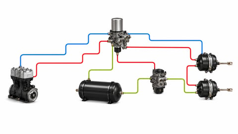
How to Read an Air Brake Diagram: Circuit Guide
How do you read an air brake system diagram? Symbol language, line colours, port codes, circuit split, trailer lines and fault-tracing, step by step.


