How to Test an ABS Sensor: Resistance, Signal and Tone Ring Checks
How to test a heavy-duty ABS wheel speed sensor: resistance, AC signal, active sensor supply, air gap and tone ring checks step by step.
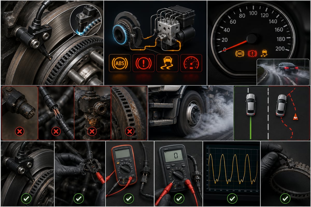
A tractor unit rolls into the workshop with the ABS light on. The scan tool points to the right-front wheel speed sensor, the sensor gets swapped, and the light goes out. Twenty kilometres later it comes back on. Almost never is the sensor itself the real cause of that loop: the code pointed at a location, but nothing at that location was actually measured. The ABS wheel speed sensor is one of the cheapest electronic parts on a heavy commercial vehicle, yet at least five separate physical faults can trigger the exact same code, and only one of them is the sensor. This guide is not a symptom list. It is the sequence of measurements a technician with a multimeter runs before a single part gets ordered.
Before You Start Measuring: Which Circuit, How Many Sensors, What Architecture?
The first step in any measurement is not electrical, it's conceptual: measuring without first knowing which ABS architecture the vehicle runs sends you looking for the right number in the wrong place. On heavy commercial vehicles, the number of sensors and the number of channels are often not the same thing. A common tractor layout runs four sensors and four modulators; three-axle trucks are also built with six sensors and four modulators, where the two extra axles are read separately but their brake control is paired. In other words, a fault report that says "right rear" can point at either of two candidate wheels, not one.
The second distinction sits between the tractor and the trailer. A trailer carries its own electronic braking unit, its own sensors and its own fault memory; a sensor fault invisible in the tractor's memory can surface the moment the trailer is coupled to its own unit. For a refresher on how the overall system works, the heavy-duty air brake ABS system guide is the background this measurement guide builds on.
This article deliberately keeps a narrow scope: it covers how to measure the sensor. The symptoms a driver actually notices, the replacement steps for the sensor and the control unit, the periodic maintenance schedule and part selection are a separate subject; the ABS wheel speed sensor and ECU faults, replacement and care guide gives that wider framework. Once a measurement shows a part actually needs to come off, that guide picks up where this one ends.
Two conditions are confirmed before turning to the sensor side at all. The control unit's supply voltage and its ground connection to the chassis must both be sound; if either one is faulty, the system produces implausible readings even with sensors that are otherwise fine. The fault memory should also be logged and cleared: there is no way to tell a fault that occurred months ago and cleared itself apart from one that is present right now. Clear the codes, drive the vehicle, and see which one comes back.
ABS Sensor Types and Why the Measurement Method Changes
Two basic sensor families work side by side in the heavy vehicle fleet, and the difference between them isn't just the technology; the measurement method changes completely. Apply the wrong method to the wrong family and you can scrap a good sensor while sending a faulty one back onto the truck.
A passive inductive sensor is a coil built around a permanent magnet. It has no external supply: as the teeth of the tone ring pass in front of it, the magnetic field changes and an alternating voltage is induced in the coil. Because the signal's amplitude rises with speed, it weakens at very low speed and drops below a threshold the system can no longer read at all below a certain point. Testing this family is classic: coil resistance, and the AC voltage produced when the wheel is turned by hand.
An active sensor, by contrast, carries its own electronic circuit. A Hall-effect or magnetoresistive sensing element runs on a regulated supply from the control unit and converts wheel speed into a digital signal. The most common heavy-vehicle implementation is a two-wire design that carries information by switching its current draw between two levels, and the control unit counts the frequency of that switching. Its advantage is that it can produce a usable signal even when the wheel is almost stationary, and some designs can also report direction of rotation. Its biggest trap is this: measuring resistance on the ohms range means nothing on an active sensor — the reading reflects how the internal circuit behaves and depends on the voltage the meter itself applies, not a coil's resistance.
| Sensor type | Has its own supply? | Signal produced | Measurement to apply | Expected value (general reference) |
|---|---|---|---|---|
| Passive inductive (coil, magnet) | No, generates its own voltage | AC voltage whose amplitude and frequency rise with speed | Coil resistance, AC voltage when turned by hand, waveform shape on a scope | Resistance in the kilohm range; a few hundred millivolts at hand speed |
| Active, two-wire (current-modulated) | Yes, regulated supply | Square-shaped signal switching between two current levels | Supply voltage, current clamp or series measuring resistor, oscilloscope | Signal switches between two stable current levels |
| Active, three-wire (separate signal line) | Yes, supply and ground separate | Square-wave voltage signal | Supply voltage, oscilloscope on the signal line | Amplitude doesn't vary with speed; signal swings between two voltage levels |
| Active sensor with magnetic ring integrated into bearing seal | Yes | Digital signal read from a magnetically coded ring | Supply and signal measurement, magnetic imaging of the ring | Poles must be evenly spaced; a missing pole leaves a gap in the signal |
The figures in the table only answer the question "is this reading in the right ballpark" — the actual acceptance range always comes from the current OE service document matched to the vehicle's engine and chassis code. The most practical way to tell whether a given sensor is passive or active is to unplug the connector, turn the ignition on, and look for voltage at the vehicle-side terminals: if voltage is present, the system is expecting an active sensor.
What Tools Do You Measure With? Multimeter, Oscilloscope and Scan Tool
ABS sensor diagnosis is a three-layer process, and each layer sees something the others can't. The multimeter is the first layer: it catches an open circuit, a short, lost insulation and a missing supply, and it closes out a large share of faults right there. What it can't do is see a signal dropout that lasts a thousandth of a second — it only reads an average.
The oscilloscope is the second layer, and it's the instrument that actually settles ABS diagnosis. Because it shows the shape of the waveform the sensor produces, it makes visible the amplitude dip left by a single broken tooth, the falling peak height as the air gap grows, and the exact point where a signal drops out. On a passive sensor you're looking for a clean sine wave; on an active sensor, a square wave with sharp edges and stable levels.
The scan tool is the third layer, and on its own it's the most misleading one: the wheel speed it displays isn't the raw signal, it's the control unit's interpretation of that signal. Its strength is that it lines up four or six wheels side by side, which exposes dynamic deviations a static bench measurement can never catch. Alongside these three, a short list of small tools matters too: a mirror and torch to inspect the tone ring, a feeler gauge set where the sensor is accessible, and a suitable hook to back the sensor out of its bore by turning it.
How to Measure Resistance on a Passive Inductive Sensor
Resistance measurement is the fastest test of the electrical integrity of the coil and its cable. Its value lies less in the absolute number than in how close it is to the sensor on the same axle: two sensors of the same age running in the same environment should read close to each other, and a clear gap between them always has a cause.
- Secure the vehicle on level ground, apply the parking brake, chock the wheels you're not measuring, and switch off the ignition.
- Unplug the sensor connector without forcing the locking tab. If it's dirty, blow it out with compressed air first — trapped moisture and salt residue will bias the result toward a wiring fault.
- Set the multimeter to the ohms range and touch the probes together, noting the reading; that's the probe leads' own resistance, and it gets subtracted from the result.
- Read the resistance across the sensor's two terminals. Take the measurement as close to the sensor as possible — at the sensor's own plug — so the wiring harness doesn't creep into the result.
- Measure the matching sensor on the same axle the same way and write both values side by side. A small gap means both coils are in similar condition.
- Interpret the result: infinite resistance means a broken coil or cable, a value near zero means a short inside the coil, and a value in the expected range that sits well apart from the paired sensor means partial degradation.
- With the probes still connected, gently work the harness by hand from the sensor's own exit point up to the connector while watching the display. A reading that jumps or briefly goes to infinity gives away a wire that has started to break internally. Skip this step and most of these faults get closed as "sensor good," only for the truck to come back a week later.
- Test insulation by measuring each terminal against the vehicle chassis in turn; a healthy sensor reads very high resistance here. A low value points to scuffed insulation or moisture inside the housing.
- Log the measurement along with its conditions: which wheel, what value, what ambient temperature. Coil resistance shifts with temperature, so a cold-morning reading and one taken at a hot brake hub won't match exactly.
- Lock the connector back into place and route the cable back along its original path and clips; a connector left loose turns the fault you just measured into a bigger one.
The limit of resistance testing has to be kept in mind: a resistance value in the expected range does not prove the sensor is good. This test only shows that the coil isn't open or shorted. A sensor with a weakened magnet, metal dust built up on its tip, or an air gap that has grown can give a perfect resistance reading while producing no usable signal at all. Resistance measurement is therefore not the end of the diagnosis — it's the precondition for the second step.
The AC Voltage Test: Measuring Signal Output by Spinning the Wheel by Hand
This is the test that actually shows whether the passive sensor is doing its job. Because the sensor generates its own voltage, spinning the wheel by hand is enough of a stimulus for the measurement — no supply of any kind needs to be applied to the vehicle.
The procedure is simple: raise and secure the wheel you're measuring, unplug the sensor connector, set the multimeter to its lowest AC voltage range, connect the probes to the sensor's two terminals, and turn the wheel by hand at a steady pace of roughly one revolution per second. What you're looking for is a stable AC reading throughout the rotation; a reading in the range of a few hundred millivolts at hand speed shows the sensor and the tone ring are working together. No voltage at all, or a reading that fluctuates, is a problem — the same measurement on the opposite wheel gives you your comparison point.
The test is powerful on its own because it checks three things at once: the coil's ability to generate voltage, the strength of the magnet's field, and whether the tone ring's teeth are close enough and sound enough to actually disturb the magnetic field. On a wheel where resistance is normal but AC voltage comes out low, suspicion shifts away from the sensor and toward the air gap, the tone ring, or metal dust built up on the sensor tip.
The same measurement on an oscilloscope says more. The waveform on screen should be a regular sine wave: peaks of equal height, evenly spaced. One peak sitting low, or missing entirely, points to a damaged or broken tooth on the tone ring, and the wheel reproduces the same dip at the same point every revolution. All the peaks sinking together, on the other hand, shows the air gap has grown — and because a multimeter only reads an average, it can't tell these two conditions apart.
Checking Supply and Signal on an Active Sensor
On an active sensor the measurement order runs in reverse: check what's being fed to the sensor first, then what the sensor produces. Because it doesn't generate its own voltage, a perfectly good active sensor with no supply looks just as dead as a faulty one.
The first step is measuring the supply. Unplug the connector, turn the ignition on, and look for the correct voltage at the vehicle-side terminals; what you're reading is the voltage the control unit regulates, and it can sit below battery voltage — what matters is that it's present and stable. No voltage means the fault sits in the control unit, the fuse or the harness, not the sensor. Voltage present but clearly lower than on the matching wheel means resistance has built up somewhere along the line, usually at an oxidised pin.
The second step is the signal measurement, and here the two-wire, current-modulated design needs its own method: the sensor sends information not by varying voltage, but by switching the current it draws between two levels. There are two practical ways to see this signal: a current clamp on the supply line tracking the transitions, or reading the voltage drop across a small measuring resistor wired in series, viewed on an oscilloscope. Turn the wheel slowly and you should see a regular square wave on screen with sharp edges and two stable levels; either level drifting, or the edges rounding off, shows the sensor or the line has degraded.
Shorts and Insulation: Leakage to Ground, to Supply and to a Neighbouring Circuit
The codes the control unit produces usually distinguish between "no signal" and "short circuit," and that distinction sets the direction of the measurement. Looking for an open circuit is easy; looking for a leak is the most elusive category of fault, because it often only shows up under specific conditions.
Three leakage paths get tested. First, leakage to chassis ground: measure each sensor terminal against the vehicle body in turn, expecting a very high resistance; a low value shows the cable's insulation has been scuffed or water has entered the connector. Second, leakage to a supply line: an unwanted connection between the sensor circuit and a supply circuit, usually forming at a pinched harness or a poorly sealed splice. Third, leakage to a neighbouring channel: when insulation breaks down between two sensor wires running in the same harness, the two wheels contaminate each other's signal and the system frequently flags both as faulty at once.
The most effective way to find a leak is under wet, vibrating conditions: a cable that shows perfect insulation dry and stationary can start leaking in the rain or under road vibration. Spraying water on the harness's chafe points and shaking the harness by hand is the most practical way to reproduce the fault back in the shop.
Standards and further reading
This subject is governed by the equipment rules for air-braked commercial vehicles. In the United States the federal air brake standard, FMVSS 121 (49 CFR 571.121) defines the reservoirs, protection and timing a compliant system must provide, and Europe applies the equivalent limits of UNECE Regulation No. 13. For further detail, see the illustrated reference guide at airbrakecompressor.com. Always confirm specific figures against the current regulation and the vehicle manufacturer service data.
Outside the United States the equivalent duties sit in national law. In the United Kingdom, regulation 18 of the Road Vehicles (Construction and Use) Regulations 1986 requires every part of the braking system to be maintained in good working order. In Canada, air brake systems fall under the Motor Vehicle Safety Regulations, which contain CMVSS 121.
How a Wiring or Connector Fault Gets Blamed on the Sensor
A significant share of the ABS sensors replaced in the field are perfectly good; the fault sits not in the sensor but in the path that connects it to the control unit. The reason is location: the sensor cable runs close to the wheel, through a zone that flexes every time the suspension moves, gets exposed to salt water in winter and to the wash-down gun year-round.
| Observed behaviour | Most likely source | Distinguishing measurement |
|---|---|---|
| Code is always present, wheel speed reads zero in every condition | Broken coil or cable, connector unplugged | Resistance at the sensor's own plug, then the same measurement at the control unit's plug |
| Code only comes up on rough roads or in corners | A wire starting to break inside the cable, a loose pin | Working the harness by hand with the probes connected, a logged road test |
| Code only comes up in rain or after a wash | Water entering the connector, scuffed insulation | Insulation to chassis, spraying water on the chafe point |
| Deviation at low speed, corrects itself at higher speed | Large air gap, low signal amplitude | AC voltage when hand-turned, peak amplitude on a scope |
| A spike that repeats at the same point every revolution | Broken or damaged tooth on the tone ring | Missing peak on a scope, a full 360-degree visual check of the ring |
| One wheel consistently reads slightly different | Different tyre diameter or a tone ring with a different tooth count | Live data at steady speed, tyre and ring inspection |
| Two channels on the same axle fault together | Shared harness, shared connector or a shared ground point | Insulation and continuity on the harness's shared section |
| Code comes up once the trailer is coupled, tractor alone is clean | Trailer socket, coiled cable, trailer-side unit | Connecting to the trailer's own unit and reading its own fault memory |
The most reliable way to separate a wiring fault from a sensor fault is to measure from two points: read resistance on the same circuit first at the sensor's own plug, then at the connector on the control unit side. A noticeably higher reading at the second point shows the difference is being built up in the cable and connectors. The gap should be small; when it grows, the source is usually an oxidised pin or a wire that has started to break internally.
The Tone Ring: The Part That Causes Faults While the Sensor Reads Fine
The tone ring — also called the reluctor ring or ABS ring — is the toothed or magnetically-poled component that spins with the wheel. The sensor reads this rotating ring; when the ring is damaged, the signal degrades even if the sensor itself works perfectly. One of the most common mistakes made in the field is replacing the sensor without ever checking the ring.
Where the ring sits varies by vehicle: in some layouts it's a separate part pressed onto the axle shaft or wheel hub; in some more recent designs it's a magnetically-poled band built into the wheel bearing's seal. This second type has no teeth and looks, to the eye, like a plain seal — damage to it can't be seen by looking.
Damage Patterns to Look for on the Ring
- Broken or missing tooth: caused during installation or by a stone strike. Shows on the oscilloscope as one missing peak at the same point every revolution.
- Corrosion and scale build-up: on salted roads, the gaps between teeth fill with rust and the teeth lose their magnetic definition; signal amplitude drops and low-speed readings disappear.
- A loose ring: once a press-fit ring loosens in its seat it stops turning at the same speed as the wheel; the speed reading sits below the real value and becomes erratic.
- Metal dust and mud build-up: metallic dust shed by the brake lining sticks to the magnet at the sensor tip, both narrowing the gap and distorting the magnetic field; it shows up as a caked-on mass at the tip.
- Damage to the magnetic ring, or the ring fitted backwards: when the pole pattern is disturbed, or the ring goes in with the wrong face outward, the sensor gets no signal at all.
Checking the ring means raising the wheel, turning it slowly, and inspecting it through the sensor bore with a mirror and torch through a full 360 degrees. Looking for teeth is useless on the magnetic-band type; the pole pattern is judged with a magnetic-viewing card or by irregularities in the oscilloscope waveform. This check matters especially on vehicles that have had hub or bearing work done: damage to a bearing-integrated ring during a bearing swap is a common fault whose source gets found far too late.
The Air Gap: What It Is, How to Measure It, and How Dirt Affects It
The air gap is the distance between the sensor's reading face and the tone ring, and on a passive sensor it directly sets signal amplitude. As the gap grows, the magnetic change the sensor sees weakens; past a certain point, the voltage produced at low speed falls below the control unit's threshold. The result is typical: the ABS warning comes on while the vehicle is slow and clears itself once speed builds.
On most heavy commercial vehicles this gap isn't set with an adjustment screw. The sensor sits in a friction bushing that grips it tightly in its bore and is pushed in until it touches the tone ring; on the first few revolutions, the ring's own runout pushes the sensor back slightly and the working gap sets itself. The weak point in this design is the bushing: a worn, corroded or reused bushing can't hold the sensor in place, the sensor creeps back over time, and the gap grows.
Where the air gap is accessible, it's measured with a feeler gauge; as a general reference, a range of roughly two tenths of a millimetre up to one and a half millimetres is expected, with the exact acceptance range coming from the vehicle manufacturer's documentation. Because access usually isn't possible, the practical method is indirect: the AC voltage measured by hand-turning, or the peak amplitude on an oscilloscope, tells you whether the gap is reasonable. Three causes of a growing gap get weighed together: the sensor creeping back inside its bushing, dirt and rust built up on the sensor tip and the ring, and play in the wheel hub bearing. That last one matters especially — on a wheel with increased bearing play, the sensor moves closer to and farther from the ring on every revolution, and the fault only ever shows up on the road, only in corners.
Live Data on the Scan Tool: Comparing Wheel Speeds
Static measurements catch opens and leaks; only live data shows what the system is actually seeing. The logic of this test is simple: four or six wheels travelling the same road, at the same time, at the same speed, should read close to each other. The channel that diverges is the fault's address.
- Connect the scan tool, select the brake control unit, and display all wheel speed channels on one screen at once, ideally as a graph — reading numbers alone hides short-lived spikes.
- With the vehicle stationary, confirm every channel reads zero. A channel reading anything other than zero while the vehicle is parked means noise or a leak.
- Drive the vehicle on a flat, open road, starting at walking pace and building speed in stages. A channel that diverges at low speed falls into the air-gap or weak-signal group.
- Record a few seconds at a steady speed and compare the channels side by side; the difference between them should be small and stable.
- Drive over rough surfaces, take gentle corners, and work the suspension. A channel that only diverges under these conditions points to the wiring and connector side.
- Apply the brakes and watch whether the channels behave together once ABS engages.
- Stop the recording and note the moment of any spike, the speed at which it occurred, and how often it repeats. A spike that repeats at a specific speed points to a source tied to wheel rotation — the tone ring or hub play.
- Read the fault memory again after the road test; a code that didn't appear during the test is a fault that isn't present right now.
Two mistakes come up often when reading live data. The first is tyre diameter: tyres worn to different levels, or of different sizes, produce a persistent speed difference even with sensors that are entirely healthy. The second is a tone ring with a different tooth count: on a vehicle with a repair history, the two sides of the same axle can end up with different rings fitted; the two wheels then diverge by a fixed ratio that no electrical test will ever catch. On vehicles with electronic braking, wheel speed data also feeds the pressure control side; for the secondary fault codes a modulator fault can generate, the EBS modulator guide gives a complementary framework.
Which Wheel Does the Fault Code Actually Point To? Confirming the Code
The "left-front wheel speed sensor" text a scan tool prints is a translation of the control unit's own channel naming, and it doesn't always line up exactly with the vehicle's physical layout. On three-axle vehicles the channel order for the second and third axles can be swapped, trailer axle numbering can start from the front or the rear depending on the manufacturer, and on a vehicle that has had harness repairs, two channels' plugs can end up switched.
The most reliable way to confirm this is physical stimulus: raise the vehicle, keep all channels live on the scan tool, and turn each wheel by hand one at a time. Whichever channel moves when a given wheel is turned — that's the confirmed match. A second method is unplugging the suspect sensor's connector with the ignition off to wake the system, then watching which code appears.
The wording of the code itself also sets the direction of the measurement. A "no signal" code points toward an open circuit or the supply side; a "short circuit" code points toward an insulation measurement; an "implausible signal" code points toward comparing against the other wheels; an "intermittent signal" code points directly at the wiring and connector side. Whether the code is permanent or pending, how many drive cycles it has repeated over, and the speed and voltage data in any freeze frame all tell you the conditions under which the fault occurs. Clearing a memory without reading it first throws away the most valuable clue in the diagnosis.
Cleaning, Installation, and the Mistakes That Undo a Good Measurement
A correctly performed measurement becomes meaningless if the sensor is removed or installed badly. An ABS sensor is a cheap part, but its bore, its bushing and its cable belong to the vehicle — damage there stays there.
The first rule on removal is to take the sensor out by turning it, not pulling it. A sensor seized by corrosion snaps in two when it's pulled with pliers, leaving its tip stuck in the bore; worked free with a proper hook, turning on its own axis, it comes out of the corrosion instead of through it. The second rule is to clean around it before removal; dirt that falls into the bore stops the new sensor from seating and throws off the air gap.
Four points decide the installation. The friction bushing gets renewed at every removal; a reused bushing can't hold the sensor in place. The bore is cleaned of scale and rust with a proper cleaning tool, never scraped with a screwdriver or a chisel. The sensor and bushing are coated with the mounting grease the manufacturer specifies; an arbitrary grease can harden with heat and lock the sensor in place. The sensor is pushed in until it touches the ring, and the wheel is turned a few revolutions by hand to let the gap set itself. The cable is secured along its original route and in all of its clips; a cable left loose finds a chafe point within a short time.
General Reference Values and the Measurement Sequence
The table below collects the figures most often needed in the field, as orders of magnitude. These values are not for making a pass/fail decision on their own; they're for judging whether a measured result is in a reasonable range. Acceptance ranges are always written in the vehicle manufacturer's documentation.
| Measurement | General reference or criterion | What it means |
|---|---|---|
| Passive sensor coil resistance | In the kilohm range; both sides of the same axle close to each other | Infinite = open circuit, near zero = short inside the coil |
| AC voltage when hand-turned | A few hundred millivolts at hand speed | Low voltage with normal resistance points to the air gap or the ring |
| Insulation to chassis | Very high resistance | Low value = scuffed insulation or moisture in the connector |
| Active sensor supply voltage | Stable regulated DC voltage from the control unit | Its absence points to the control unit or the harness side |
| Active sensor signal | Regular square wave switching cleanly between two stable levels | A shifted level or rounded edges is a sensor or line fault |
| Active sensor measured on the ohms range | Not usable as an acceptance criterion | Reading reflects the internal circuit's behaviour, not coil resistance |
| Air gap | Roughly two tenths of a millimetre up to one and a half millimetres | Where inaccessible, assess via signal amplitude instead |
| Line resistance between sensor and control unit | Small, and similar between both ends | A clear gap points to an oxidised pin or a breaking wire |
| Wheel speed deviation at steady speed | Small, stable difference between channels | A fixed, persistent difference points to tyre diameter or a different ring |
| Friction bushing | Renewed at every removal | A reused bushing lets the sensor creep back over time |
The order of the measurement matters as much as the results themselves, and it never changes: read and log the fault memory, confirm which wheel the code actually belongs to by turning it by hand, measure the sensor statically at its own plug, repeat that measurement at the control unit end of the same circuit to find the wiring's share, test signal generation by turning the wheel by hand, assess the tone ring and the air gap by eye and by signal amplitude, and only at the end drive the vehicle to record live data. Follow this sequence and the fault's location gets measured before any part is ordered; skip it and the sensor gets replaced, the light goes out, and twenty kilometres later it comes back on. In every case, the current OE service documentation for the vehicle's engine and chassis code remains the final authority.
The control side that the sensor feeds is a maintenance subject in its own right; for modulator symptoms, replacement and care see our EBS modulator and electronic braking guide.
Shop this part: ABS Sensor
In-depth technical guide: For fault diagnosis, step-by-step replacement and service intervals: ABS Wheel Speed Sensor & ECU: Faults, Replacement & Care
Main guide: ABS Brake System: How It Works, Warning Light and Faults
Tags
Frequently Asked Questions
- How do you test an ABS sensor?
- The measurement sequence is fixed: first the fault memory is read and logged, then the code is confirmed against the correct wheel, and only then is the sensor measured statically at its own plug. On a passive inductive sensor this means coil resistance plus the AC voltage produced when the wheel is turned by hand; on an active sensor it means checking supply voltage and signal shape instead. If the static measurement comes back clean, the next step is checking the tone ring, the air gap, and comparing live wheel speed data.
- What should ABS sensor resistance be, and how do you measure it?
- On passive inductive sensors, coil resistance generally falls in the kilohm range, but the exact acceptance figure varies by vehicle and comes from the OE service manual matched to the engine and chassis code. In the field, the real benchmark isn't the absolute number, it's how close it sits to the sensor on the same axle. The measurement is taken as close to the sensor as possible, at its own plug, so the wiring harness doesn't skew the result. An infinite reading means an open circuit; a value near zero means a short inside the coil.
- Can an active (Hall-effect) ABS sensor be tested by measuring resistance with a multimeter?
- No. An active sensor contains its own electronic circuit; the value read on the ohms range isn't a coil resistance, it's how that circuit behaves against the voltage the meter itself applies, and it can't be used as an acceptance criterion. On an active sensor, first check for supply voltage at the vehicle-side terminals with the ignition on and the connector unplugged, then watch the signal on an oscilloscope or current clamp while turning the wheel. Applying battery voltage directly, or testing it with an insulation tester, will destroy the part.
- Resistance reads normal but the ABS fault code is still there — why?
- A resistance value in the expected range doesn't prove the sensor is good; it only shows the coil isn't open or shorted. A sensor with a weakened magnet, brake dust packed on its tip, or a tone ring air gap that has grown can give a perfect resistance reading while producing no usable signal at all. In that case, turn the wheel by hand and measure the AC voltage, check the waveform on an oscilloscope if one is available, and inspect the tone ring by eye.
- Can you test an ABS sensor by spinning the wheel by hand?
- Yes, on a passive inductive sensor, and it's one of the most useful tests available. Raise and secure the wheel, unplug the sensor connector, set the multimeter to its AC voltage range, and turn the wheel by hand at roughly one revolution per second. A stable reading of a few hundred millivolts at that speed shows the coil, magnet and tone ring are all working together. Repeating the same test on the opposite wheel gives you a direct comparison point.
- How do you inspect an ABS tone ring (reluctor ring)?
- Raise the wheel, turn it slowly, and look through the sensor bore with a mirror and torch through a full 360 degrees, checking for broken teeth, rust build-up, looseness, and metal dust or mud on the ring. On designs where the tone ring is a magnetic band integrated into the wheel bearing seal there are no teeth to see, and hidden damage is only found with a magnetic-viewing card or by reading irregularities in the oscilloscope waveform. A spike that repeats at the exact same point every revolution is typically the ring, not the sensor.
- What should the ABS sensor air gap be, and how is it set?
- As a general reference, a range of roughly two tenths of a millimetre up to one and a half millimetres is expected, with the exact acceptance range coming from the vehicle manufacturer's documentation. On most heavy commercial vehicles this gap isn't set with an adjustment screw: the sensor is pushed into its friction bushing until it touches the ring, and the ring's own runout on the first few revolutions pushes it back slightly to create the working gap on its own. The main causes of a growing gap are a worn bushing, dirt and rust build-up, and play in the wheel hub bearing.
- How do you tell whether the fault is in the sensor or in the wiring?
- The most reliable method is measuring from two points: read resistance on the same circuit first at the sensor's own plug, then again at the connector on the control unit side. A noticeably higher reading at the second point shows the difference is being built up in the cable and connectors. It also helps to work the harness by hand with the probes still connected — a reading that jumps or briefly spikes to infinity gives away a wire that has started to break. Codes that only appear on rough roads or in the rain point the same way, toward wiring and connectors.
- How do you confirm which wheel a fault code is actually pointing to?
- The channel name a scan tool displays is the control unit's own naming convention, and it doesn't always match the vehicle's physical layout exactly — channel order can be swapped on multi-axle trucks and trailers. The most reliable confirmation is physical: raise the vehicle, keep all channels live on the scan tool, and turn each wheel by hand one at a time to see which channel responds. Unplugging the suspected sensor's connector and watching which code appears is a useful second check.
- What do you compare wheel speeds against on a scan tool?
- All wheel speed channels are displayed on one screen at once, ideally as a graph. With the vehicle stationary every channel should read zero, and at a steady speed on a flat road the difference between channels should be small and stable. A channel that only diverges at low speed points to the air gap or a weak signal; one that only diverges on rough roads or in corners points to wiring; a spike repeating at a fixed speed points to the tone ring or hub bearing play. A constant, fixed-ratio difference usually means unequal tyre diameters or a tone ring with a different tooth count, not an electrical fault.
Related Articles
Air Dryer: Faults, Replacement & Maintenance Guide
How a truck air dryer's charge and purge cycle keeps moisture and oil out of the brake system, and what a hissing purge valve or water in the tanks means.
Brake Chamber: Faults, Replacement & Maintenance Guide
Service and spring brake chambers on trucks and trailers: diaphragm-leak and stroke diagnosis, why caging is mandatory before removal, and safe replacement.
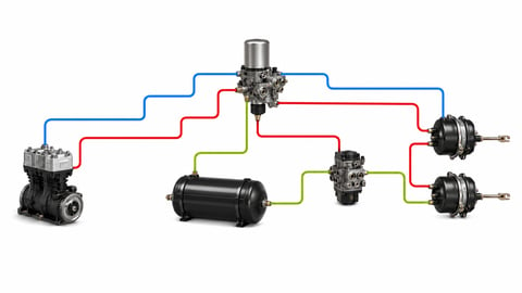
How to Read an Air Brake Diagram: Circuit Guide
How do you read an air brake system diagram? Symbol language, line colours, port codes, circuit split, trailer lines and fault-tracing, step by step.


