What Is a Crankshaft? Function, Failure Symptoms and Maintenance
What is a crankshaft? Its function in heavy-duty engines, bearing seizure and failure symptoms, measurement, regrinding and maintenance guide.
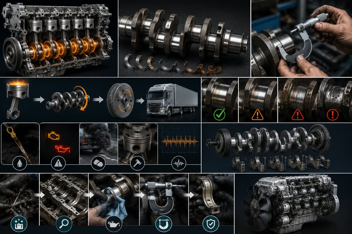
A loaded tractor pulls away on an incline and a deep, dull knock rises from low in the engine; ease off the throttle and it fades, load the engine again and it returns. At hot idle, the oil pressure warning flickered on the dash for a moment. Back in the shop, the drain plug comes out and the oil is thinner than it should be, with fine, bright metallic flakes on the magnetic plug and in the pickup strainer. That picture points to the engine's load-bearing backbone: the crankshaft and the bearings that carry it. This guide treats the crankshaft not as an isolated shaft, but as the central member of the piston-rod-bearing-oil chain, whose health depends on the whole chain rather than on itself alone.
What is a crankshaft? The main shaft that turns linear motion into rotation
The crankshaft is the main shaft that takes the linear, back-and-forth motion created when combustion pressure drives the piston down and converts it into continuous rotation through the connecting rods, collecting the engine's entire output torque on itself. The power produced is sent rearward, through the flywheel, to the drivetrain, and forward, through the pulley, to accessory units such as the alternator, the air brake compressor, the power steering pump and the water pump.
Picturing the crankshaft as a plain, straight bar is the most common misunderstanding of the part. Sections sitting on the axis of rotation alternate along the shaft with sections deliberately offset from that axis. The ones on the axis carry the shaft inside the block; the offset ones turn the piston's up-and-down travel into rotation around a fixed radius. That offset sets the engine's stroke: stroke is exactly twice the crank throw radius. This is the geometric reason long-stroke, heavy-duty diesel engines produce strong torque at low engine speed. The shaft is made up of:
- Main journals: the surfaces on the axis where the shaft is supported inside the block. An inline six-cylinder engine typically carries seven main bearings.
- Rod (crankpin) journals: the offset surfaces gripped by the big end of the connecting rod — the section that turns applied force into torque.
- Crank webs and counterweights: the body sections linking the journals, and the projections that offset the centrifugal force of the rotating masses.
- Oil holes and internal passages: the drillings carrying oil from the main journal, through an angled hole bored inside the web, out to the rod journal.
- Front and rear ends: at one end, the pulley, timing gear and front seal surface; at the other, the flywheel flange, rear seal surface and sensor target ring.
The journals are machined and hardened to a near mirror finish, yet the most critical zone on the shaft is the fillet radius where each journal blends into its web. Because stress concentrates there, fatigue cracks almost always start in this radius rather than on the bearing surface. Axial float of the shaft is limited by a thrust bearing surface beside one of the main bearings.
What is the difference between the crankshaft and the camshaft?
The crankshaft is supported in the lower section of the engine; it takes in the pistons' motion and sends power out. The camshaft, by contrast, is the timing shaft — its lobes decide when the valves, and on some designs the unit pump-injectors, are actuated. Put simply, the crankshaft carries force and the camshaft carries timing. The two are linked by gear, chain or belt, and in a four-stroke engine the crankshaft turns twice for every turn of the camshaft; one full cycle needs 720 degrees of crankshaft rotation. Failure symptoms on the camshaft side are covered in the camshaft guide.
How does a crankshaft work? Force path, firing order and continuity
Pressure generated by combustion loads the piston crown directly. The piston passes that force through its wrist pin to the connecting rod, and the rod carries it, through its big-end bearing, onto the rod journal. Because the journal sits offset from the axis, the force acts across a lever arm and a turning effect results: torque equals that force multiplied by the crank throw radius. The efficiency of this conversion changes with crank angle — smallest at top dead centre, reaching its peak once the shaft has rotated some way past it. Ignition timing is set around this geometry.
In a four-stroke engine, each cylinder produces power in only one of its four strokes; for the other three, what keeps the crankshaft turning is force from the other cylinders plus the inertial energy stored in the flywheel. On an inline-six heavy-duty diesel, the 720 degrees of a cycle are shared equally across six cylinders, so firing events land every 120 degrees and power delivery is close to continuous. The inline-six layout is also naturally balanced, since its first- and second-order inertia forces cancel each other out. A common firing order is 1-5-3-6-2-4, though it varies by engine code.
Because firing events land at different points along its length, the crankshaft twists slightly and springs back with every combustion event. This torsional vibration grows at speeds close to the shaft's natural frequency and is the leading source of fatigue cracking; the damper on the front end exists to absorb that energy. The shaft carries three loads at once: compression, bending and torsion.
Mapping the engine's internal mechanicals: the chain from crankshaft to valve
The crankshaft rarely fails in isolation. An engine's internal mechanicals form a connected chain, and a fault anywhere along it most often shows up first as a symptom at the crank bearings. The chain runs: crankshaft, connecting rod, piston and rings, liner, cylinder head, valves, rocker gear and camshaft.
| Component | Function | Result of its fault, as seen at the crankshaft |
|---|---|---|
| Main bearings and block housings | Support the crankshaft on an oil film, on axis | Wear drops oil pressure and produces a deep knock from below |
| Connecting rod and big-end bearing | Transfers piston force onto the rod journal | A bent rod wears the journal at an angle, bearing wears one-sided |
| Piston, rings and liner | Holds combustion pressure, passes force through the wrist pin | Rising blow-by dilutes the oil until the film can no longer carry load |
| Cylinder head and gasket | Closes the combustion chamber, carries the valve train | A coolant or fuel leak mixes into the oil and bearing corrosion begins |
| Valves, rocker gear and camshaft | Sets timing, manages intake and exhaust flow | Timing drift means added knock and greater load on the bearings |
| Oil pump, galleries and filter | Delivers pressurised, clean oil to the bearings | Falling pressure or flow interrupts the oil film and the bearing wipes |
| Flywheel, pulley and torsional damper | Stores inertia, absorbs torsional vibration | A dead damper and a shaft running untrue fatigue the metal and open up the seals |
None of these relationships run one way only. A worn piston-and-liner pairing doesn't just cost compression; gases blowing past into the crankcase dilute the oil and load it with soot, which shortens bearing life directly. That wear behaviour is covered in the engine piston and liner guide. Leakage from above works its way down just as readily: a head with a failed gasket that lets coolant into the sump starts bearing-surface corrosion almost immediately; the head's own failure symptoms are described in the engine cylinder head group guide.
Crankshaft materials and manufacture: forging, casting and surface hardening
The crankshaft carries the heaviest fatigue load of any part in the engine, and its manufacturing route reflects the power density it must withstand. In a forged crankshaft, a heated steel billet is shaped between dies; because the grain flow follows the part's shape and stays unbroken through the radius zones, fatigue strength is high. This is the usual choice on modern high-cylinder-pressure engines. A cast crankshaft in nodular, spheroidal-graphite iron allows a complex shape to be produced in one step, more cheaply; the spherical graphite gives a much tougher structure than grey cast iron, though its strength still falls short of a forged shaft's.
Once the raw shaft is shaped, its real strength is added through surface treatment: the journals are hardened and the fillet radius is separately reinforced.
| Treatment | What it does | What it means for service |
|---|---|---|
| Induction hardening | Builds a hard case on the journal surface | Grinding depth is limited; once the case is gone, the shaft is finished |
| Nitriding | Produces a very thin, very hard surface layer | May need re-treatment after any regrind; the OE rule is decisive |
| Fillet rolling | Rolls compressive stress into the transition radius | If grinding disturbs the radius, resistance to cracking is lost |
| Grinding, polishing and dynamic balancing | Brings the journal to final size, removes remaining imbalance | Surface finish affects the oil film, and balancing has to be repeated |
What this means on the shop floor is straightforward: a crankshaft cannot be reworked an unlimited number of times. The hardened layer is thin, and every regrind removes a further slice of it. On some engines the crankshaft is defined as non-regrindable outright; that call is set by the OE documentation, not by what a grinding machine happens to be capable of.
Main and rod bearings: the micron-thick film that carries the crankshaft
The crankshaft never sits metal-to-metal in the block. A thin film of oil separates the main journals from their bearing shells, and the shaft floats on that film. This mechanism is called hydrodynamic lubrication: the rotating journal drags oil in the clearance into a converging, wedge-shaped gap, and the pressure that builds in that wedge generates enough load-carrying capacity to lift the shaft. Oil pump pressure doesn't build this film directly — its job is to keep enough flow reaching the clearance without interruption.
The half-shell bearings are a soft lining layer cast onto a steel back. That softness isn't a flaw; it's a design choice: it lets small, hard particles carried in the oil embed themselves in the lining instead of scoring the journal. Two-layer bimetal bearings use an aluminium-tin lining; three-layer trimetal bearings, preferred in heavily loaded applications, add a thin sliding overlay on top. The locating tang on the shell back positions the bearing but doesn't retain it — what holds it in place is the hoop stress the shell develops once the cap is torqued down.
What is bearing clearance, and why does it matter this much?
Bearing clearance is the difference between the journal diameter and the installed bearing's inside diameter, and it's one of the most sensitive dimensions in the engine. If the clearance is too tight, oil can't get into the gap fast enough; the film thins, friction heat climbs and the bearing wipes quickly. If it's too loose, oil escapes rapidly, pressure falls, and the journal slaps against the bearing on every firing event — the mechanical origin of that deep knock from underneath the engine. Measurement is done with the Plastigage method, or a micrometer and bore comparator.
Thrust bearing and end play
Axial travel of the shaft is limited by a thrust bearing, or thrust washers, fitted either side of one main bearing. As end play grows, the shaft moves fore and aft: movement shows up at the pulley, oil weeps past the rear seal, and the clutch linkage behaves erratically. The most common enemy of the thrust bearing is a driver's habit of resting a foot on the clutch pedal; it keeps pushing the shaft forward and starves the thrust face of its oil film.
Oil galleries and dependence on oil pressure
Pressurised oil reaches the main journal first, through a gallery in the main bearing housing, then travels through an angled hole drilled inside the crank web to reach the rod journal. In other words, the oil a rod bearing gets has already passed through a main bearing; when main clearance grows, or a gallery narrows with soot and sludge, the rod bearing downstream starves first. A pressure drop at hot idle is normal; edging toward the warning threshold is not. As bearings wear, total leakage area grows and pressure falls permanently — which is why oil pressure remains the earliest, most reliable health indicator for the crank bearings.
How do you recognise crankshaft failure symptoms?
Symptoms mostly present through the bearings and develop in stages: first a quiet drop in oil pressure, then a noise under load, and finally vibration with visible metal debris.
| Symptom | Likely mechanism | First check |
|---|---|---|
| Deep, dull knock from low in the engine | Main bearing clearance has grown, journal slapping the bearing | Listen for the change in sound under load, measure oil pressure |
| Metallic rattle that rises under load, fades off-throttle | Rod bearing clearance has grown, or the bearing is damaged | Cylinder cut-out test to isolate the affected cylinder |
| Oil pressure dropping at hot idle | Total bearing leakage area has grown, film is weakening | Measure with a mechanical gauge, confirm against the dash reading |
| Constant oil leak around the rear seal | Seal surface worn, or crankcase pressure running high | Check crankcase breather flow before replacing the seal |
| Noise changes and fore-aft movement when the clutch is pressed | Thrust bearing worn, end play has grown | Measure end play with a dial indicator |
| Hard to turn over on the starter, engine will not crank | A bearing has seized, shaft locked in its housing | Try turning the engine over by hand, open the oil pan |
Most of these symptoms are not unique to the crankshaft. A loose pulley bolt, a worn wrist-pin bushing or a partly blocked oil strainer can produce a similar picture. Because the engine block itself carries sound, a stethoscope reading loudest at one point doesn't by itself confirm the fault sits there.
How does a bearing seize? Mechanism and main causes
What gets called "the bearing spun" in the field is not a single instant failure — it's a short chain of events that feeds on itself. The oil film loses its load-carrying capacity at some point, the journal contacts the lining, friction heat climbs fast, the soft lining flows under that heat and smears onto the journal surface, the smeared material narrows the gap further, and the process accelerates. Eventually the lining is gone, the steel back cuts into the journal, and the shell starts spinning inside its housing; once it spins, the oil feed hole seals shut.
The damage doesn't stop there. The heat released can alter the heat-treatment of that section of shaft and leaves visible bluing on the journal; the spinning shell also grinds away the block housing. That's why the block housings need measuring too, on any engine that has spun a bearing.
- Insufficient oil pressure or flow: a low oil level, a worn oil pump, a blocked pickup strainer, or a relief valve stuck partway open.
- A blocked oil gallery: the angled hole inside the crank web, or a passage in the block, narrowed by accumulated soot, sludge or leftover regrind debris.
- Wrong viscosity or degraded oil: oil outside the approved grade, an oil change interval that ran long, fuel dilution, coolant contamination, or a filter change put off too long.
- Wrong bearing clearance and assembly errors: fitting a bearing without measuring first, using the wrong undersize, an uncleaned housing, dirt trapped behind the shell back, or bolts torqued to the wrong value or in the wrong sequence.
- Overloading and geometric faults: heavy load carried at low engine speed, loading a cold engine before it has warmed up, a bent connecting rod, an out-of-round housing, or a shaft that no longer runs true.
What this list means in practice is that a seizure is a result, not a starting cause. If the underlying reason isn't found before the engine goes back together, the replacement bearing typically lives out the same short life. Examining the bearings that came out is the fastest route to an answer; the shape and colour of the wear pattern usually tell you directly which mechanism was at work.
Further reading
For a plain-language technical overview of this subject, see the reference article on Wikipedia. Always confirm specific figures and procedures against the vehicle manufacturer service data.
Diagnosing the crankshaft: a step-by-step path from the road to the bench
The most expensive mistake in diagnosis is pulling an engine apart on a guess about where a noise comes from. The right approach starts with steps that are cheap and reversible.
- Pull the vehicle's history: oil change records, oil grade, recent repairs, any history of overheating, and complaints of oil consumption.
- Check the oil level and condition. If the level has risen and the oil has thinned, suspect fuel dilution; if it looks like milky coffee, suspect coolant contamination.
- Strain the oil as it drains and inspect the magnetic drain plug. Bright silver flakes point to bearing lining; coarser steel shavings point to a heavier mechanical failure.
- Measure oil pressure with a mechanical gauge rather than the dash gauge, cold and again at operating temperature.
- Listen to the noise under load and unloaded. Rod bearing noise typically rises with load and drops off when that cylinder's fuelling is cut; main bearing noise sits deeper.
- Check the pulley and flywheel side visually and with a dial indicator; slip marks on the outer ring can mean the damper has died. Measure front-end runout and end play.
- Measure crankcase pressure; a high reading explains seal leaks and points to a problem on the ring-and-liner side.
- If the findings point to the bearings, open the pan and pull one rod bearing for inspection; the wear pattern gives a read on the whole engine, then classify the damage.
The steps most often skipped here are the second and the seventh. Oil condition and crankcase pressure are the two cheapest measurements, and together they set the direction of the diagnosis — neither one requires opening the engine.
Measurement and regrinding: micrometer, crack inspection and bearing undersizes
Once the shaft is removed and cleaned, visual inspection alone isn't enough — measurement decides whether it can go back into service. Journal diameter and geometry: every main and rod journal is measured with a micrometer, at a minimum of two to three cross-sections along its length, in two directions perpendicular to each other at every section. The difference between the two directions at one section gives out-of-roundness; the difference between sections gives taper. If either exceeds the OE limit, the shaft is reground or replaced.
Runout and crack inspection: the shaft is set on V-blocks at the outer main journals, a dial indicator is placed on the centre journal, and it's rotated slowly to read deflection; a bent shaft that gets installed will wear its bearings unevenly within a short time. Any shaft that has seen heavy overload, or a seizure, should be checked for cracks; magnetic particle inspection reveals surface and near-surface cracks, and the places to check are well established: the fillet radii and the oil-hole mouths. A crack in a radius means the shaft is scrap; welding or grinding it away is never acceptable. Visible bluing means heat damage too, and the shaft shouldn't return to service until hardness has been confirmed.
If the measurements are within limits, the shaft is taken to an undersize on a grinder and matched with the corresponding undersize bearing. Common practice defines undersizes in multiples of 0.25 mm, but which sizes exist, and whether regrinding is even permitted, depends on the engine code. Three rules never change: the fillet radius is held at its original size, the oil holes are chamfered and cleaned, and the shaft is polished last. Washing and pressure-flushing the passages afterward is mandatory.
Counterweights, balancing, pulley and flywheel: managing vibration
The crankshaft also has to manage the imbalance its own design creates. Because the rod journals, and the masses rotating with them, sit offset from the axis, they generate centrifugal force; counterweights are placed on the webs to offset that force. Whatever small imbalance remains is measured on a balancing machine and usually corrected by removing material. In most designs, balancing is done with the flywheel and pulley fitted, not the bare shaft alone — so mark their position before removal.
The torsional (vibration) damper deserves its own note. It absorbs the crankshaft's torsional vibration through either a bonded rubber element or a viscous fluid-filled design. A damper is not a lifetime part: rubber ages and cracks, and the outer inertia ring shifts relative to the inner hub; on the viscous type, the fluid itself loses its damping properties. A dead damper gives no warning yet leaves the crankshaft exposed to torsional fatigue; a good share of the crankshaft failures seen in the field trace back to a damper left unchanged for years. A shifted timing mark on the outer ring is both the clearest sign of failure and the reason behind an incorrect timing reading.
The flywheel, on the rear end of the shaft, is both an inertial mass and the drivetrain interface; it bolts to the crank flange and carries the starter ring gear and clutch friction surface. Flywheel bolts are single-use on many engines and are tightened with the torque-plus-angle method. A loose or misaligned flywheel loads the rear main bearing and seal alike; a complaint starting as clutch judder can quietly turn into bearing damage over time.
Crankshaft seals and oil leaks: front and rear
The crankshaft exits the engine at both ends, and a seal sits at each exit to keep oil from escaping. The front seal sits behind the pulley, in the timing cover; the rear main seal sits just in front of the flywheel, on a separate housing in most designs. The rear main seal is the most argued-over oil leak on the engine, simply because replacing it means pulling the flywheel and, usually, the clutch assembly too.
Identifying the actual cause matters more than just swapping the seal. The usual causes are the seal ageing and losing lip flexibility, a wear groove in the shaft at the seal surface, excessive shaft movement, and the cause most often overlooked: high crankcase pressure. When breather flow is restricted, or blow-by increases, internal pressure pushes oil out at the weakest point; in that case, even a new seal leaks again before long.
One assembly rule matters most: classic rubber-lip seals go in with the lip lightly oiled, while dry-running PTFE-lip seals go in dry and are worked onto the shaft using their own installation sleeve; oiling that type defeats its sealing function from the start. To protect the lip, sharp edges on the shaft end must be covered, and the seal should be driven home with a proper mandrel — never a hammer — square to its bore.
Crankshaft replacement and assembly discipline
Replacing a crankshaft means pulling the engine from the vehicle and fully opening the bottom end. The hard part isn't manual skill so much as discipline: cleanliness, measurement, sequencing and torque. Torque values, bolt sequences and special tools vary by engine and come from the OE manual.
- Secure the vehicle, disconnect the battery, drain the oil and coolant properly, and lift the engine out onto a suitable stand with the right equipment.
- Remove the flywheel, clutch assembly, pulley, timing cover and oil pan; record the position and alignment marks of every part.
- Remove the cylinder head and the piston-and-rod assemblies. Before removing the rod and main bearing caps, confirm their numbering and orientation — caps are not interchangeable.
- Support the crankshaft as you lift it clear of its bearings. It's heavy and unbalanced; letting a journal strike a hard surface can scrap the shaft on its own.
- Measure the block's main bearing housings; if a housing is out-of-round or misaligned, replacing the crankshaft alone won't fix the problem.
- Before installing the shaft, pressure-flush every oil gallery and confirm it's clear — leftover regrind swarf is the most common killer of new bearings. Wipe the housings and shell backs with a lint-free cloth, since even one trapped particle behind a shell can close the clearance locally and trigger a seizure.
- Measure bearing clearance with the Plastigage method, or a micrometer and bore comparator, and confirm it matches the OE specification.
- Coat the bearing surfaces with assembly lubricant, seat the shaft, fit the caps in their own numbered positions and orientation, and torque the bolts to the OE value and sequence, using torque-plus-angle where specified. Rotate the shaft by hand after every cap is torqued to confirm it turns freely.
- Measure end play and confirm it's within the OE range; fit the rod assemblies, oil pan, seals, pulley and flywheel. Make sure oil pressure builds before the first start, and avoid heavy load during break-in.
Technical values and general reference ranges
The table below gathers the figures most often needed; it isn't meant for making a decision, but for judging whether a measured result looks reasonable.
| Value or criterion | General reference approach | Interpretation |
|---|---|---|
| Main bearing clearance | Narrow tolerance band set by the OE manual | Tight clearance seizes, wide clearance knocks and drops pressure |
| Rod bearing clearance | Narrow tolerance band set by the OE manual | Fed from the main bearing; if main clearance is wide, this is affected first |
| End play | Measured with a dial indicator, must fall within the OE range | A large value produces seal leaks and clutch-related complaints |
| Journal out-of-roundness and taper | Regrind or replace once beyond the OE limit | Measured at multiple cross-sections and in two directions, never one point |
| Undersizes and fillet radius | Commonly defined in multiples of 0.25 mm; radius is always preserved | A sharpened-off radius is exactly where fatigue cracking begins |
| Cap and flywheel bolts | Torque, often torque-plus-angle on most engines; frequently single-use | Skipping the method risks lost clearance, misalignment and loosening |
| Oil pressure and oil grade | Above the OE lower limit at hot idle, on an approved grade | A persistent drop shows that clearances have already grown |
The rule that never changes here: no numerical value on the crankshaft side can be used independently of the engine code. Two engines from the same maker, of the same displacement, can still call for different clearances and different regrind rules.
Maintenance, service life and the crankshaft's place in the engine
The crankshaft has no defined replacement interval. In a properly maintained heavy commercial vehicle engine, it lasts the engine's entire working life and, in most cases, is never replaced. What determines its service life isn't distance travelled but the pressure, cleanliness and temperature of the oil passing over it. Of two identical examples of the same engine, one may never have its bottom end opened, while the other goes in for an early overhaul purely because of one oil change that ran late.
- Oil and filter discipline: change on whichever comes first, distance or time, shorten the interval under severe duty, and never step outside the viscosity grade the engine approves — that choice sets film thickness directly.
- Oil level and pressure: confirm the level neither drops nor climbs, log hot-idle pressure as the vehicle's own baseline, and track the trend over time.
- Warm-up and cool-down discipline: don't load a cold engine immediately, and give it a short idle before shutdown.
- Crankcase breather, damper and records: a blocked breather causes seal leaks; check the damper periodically for cracking and ring slip; log the regrind undersize and bearing size in the vehicle file.
The crankshaft is, at once, both the most durable and the most dependent part in the engine's internal mechanicals: designed with hardened surfaces meant never to be touched, yet riding on a micron-thick oil film that the rest of the chain is responsible for keeping intact. That's why crankshaft failure is usually not the crankshaft's own fault. The correct diagnostic order is clear: first confirm the oil is clean, then that pressure is established, then that the top end is sound — the crankshaft is questioned last. In every case, the vehicle's current OE service documentation for its engine and chassis code is the final authority.
For the wear symptoms and replacement procedure of the piston and cylinder liner group that transmits this motion to the crankshaft, see the engine piston and liner guide.
Shop this part: Engine
In-depth technical guide: For fault diagnosis, step-by-step replacement and service intervals: Compressor Crankshaft & Drive Assembly: Failure & Replacement Guide
All our technical guides on this topic
- Engine Gasket Set: Failure, Replacement and Maintenance Guide
- Engine Piston & Liner: Faults, Replacement and Maintenance
- Engine Piston, Liner & Ring Set: Failure and Replacement
- Engine Cylinder Head Group: Faults, Replacement & Maintenance
- Engine Valve Train & Adjustment Shim: Faults, Replacement, Care
- What Is Valve (Rocker Arm) Clearance Adjustment? Why and When Is It Needed?
- Burnt Cylinder Head Gasket: Symptoms and Causes
- Rocker Arm & Shaft Set: Faults, Replacement and Maintenance
- Camshaft: Fault Symptoms, Diagnosis & Replacement Guide
- Flywheel Housing: Faults, Replacement & Maintenance Guide
- When Should a Timing Belt Be Replaced? What Happens If It Breaks?
- What Is a Starter Motor? Failure Symptoms and Brush Replacement
- What Is a Charging Alternator? Its Function and Alternator Failure Symptoms
VADEN ORIGINAL products
- Piston & Liner — 84 products
- Cylinder Head — 66 products
- Engine Valve — 54 products
- Eccentric — 19 products
Tags
Frequently Asked Questions
- What is a crankshaft and what does it do?
- The crankshaft is the main shaft that turns the linear back-and-forth motion created by combustion pressure into continuous rotation, through the connecting rods. It collects the engine's entire output torque and sends it rearward through the flywheel to the drivetrain, and forward through the pulley to accessory units such as the alternator, air brake compressor and water pump. Every newton-metre the engine produces passes through this shaft.
- What are the symptoms of crankshaft failure?
- The most typical symptoms are a deep, dull knock from low in the engine, oil pressure dropping at hot idle, a metallic rattle that rises with load and fades off-throttle, and vibration that changes with engine speed. In advanced cases you'll see metallic flakes in the oil pan and strainer, a constant oil leak around the rear seal, and the engine turning over with difficulty on the starter. Most of these symptoms aren't unique to the crankshaft; a loose pulley bolt or a blocked oil strainer can produce a similar picture.
- Does a knock from underneath the engine always mean the crankshaft?
- A deep knock from below most often means bearing clearance has grown, so the journal is slapping the bearing on every firing event. Rod bearing noise typically rises with load and drops noticeably when that cylinder's fuelling is cut; main bearing noise sits deeper and shows up more with changes in engine speed. Because the engine block carries sound so readily, a stethoscope alone isn't enough — it needs to be read together with an oil pressure measurement.
- What is bearing seizure, and what causes it?
- Bearing seizure happens when the oil film loses its load-carrying capacity, the journal contacts the bearing lining, and friction heat smears that lining onto the journal surface. The process feeds on itself: the lining disappears, the steel back cuts into the journal, and the bearing spins in its housing, sealing off the oil feed hole. The main causes are insufficient oil pressure or flow, a blocked oil gallery, wrong viscosity or degraded oil, incorrect bearing clearance and assembly errors.
- Can a crankshaft be reground?
- If the measurements come back within limits, the shaft is taken to an undersize on a crankshaft grinder and matched with the corresponding undersize bearing; undersizes are commonly defined in multiples of 0.25 mm. However, the hardened surface layer is thin and every regrind removes some of it. On some engines the crankshaft is defined as non-regrindable outright; the decision rests on the engine's OE service documentation, not on what a grinding machine can do.
- How many kilometres does a crankshaft last?
- The crankshaft has no defined replacement interval. In a properly maintained heavy commercial vehicle engine, it lasts the entire working life of the engine and, in most cases, is never replaced. Its service life is set not by distance travelled but by the pressure, cleanliness and temperature of the oil that passes over it; a late oil change or an unnoticed pressure drop can shorten that life considerably.
- Why does the rear main seal leak oil?
- The usual causes are the seal ageing and losing lip flexibility, a wear groove worn into the shaft at the seal surface, excessive shaft movement, and the cause most often missed: high crankcase pressure. When the breather is blocked, internal pressure pushes oil out at the weakest point, and even a brand-new seal will leak again before long. That's why crankcase breather flow should always be checked before a seal is replaced.
- What is the difference between the crankshaft and the camshaft?
- The crankshaft is supported in the lower part of the engine, takes in the pistons' motion and sends power out — in short, it carries force. The camshaft is the timing shaft; its lobes decide when and how far the valves move — it carries timing. In a four-stroke engine, the crankshaft turns twice for every one turn of the camshaft, and one full cycle needs 720 degrees of crankshaft rotation.
- How do you tell if a crankshaft is bent?
- The shaft is set on V-blocks at its outer main journals, a dial indicator is placed on the centre journal, and the shaft is rotated slowly to read the deflection. On the vehicle, visible runout at the pulley, a belt that keeps throwing, and vibration that changes with engine speed all point toward a bent shaft. A bent shaft that goes back in service loads the bearings unevenly and wears them out on one side within a short time.
- Does replacing a crankshaft require pulling the engine?
- Yes — replacing a crankshaft means pulling the engine from the vehicle and fully opening up the bottom end. The flywheel, clutch assembly, pulley, timing cover, oil pan, cylinder head and piston-and-rod assemblies all come off first, followed by the main bearing caps, each in its own numbered position and orientation. The hard part of the job isn't manual skill so much as discipline: cleanliness, bearing-clearance measurement, correct sequencing and OE torque.
Related Articles

Oil Filter Cap and Housing: Leaks, Cracks and Seal Replacement
Truck engine oil filter cap and housing: why plastic caps crack, O-ring leak causes, bypass valve faults, and correct torque and seal replacement steps.
Piston Rings: Oil Consumption, Compression Loss and Replacement
Ring-related oil consumption and compression loss in truck diesel engines: how rings seal, blow-by and leak-down tests, ring gap and replacement.
Intake Manifold and Intake Pipe: Faults, Diagnosis, Repair
How the intake manifold and charge air pipe work on truck diesel engines, how to spot boost leaks, run a pressure test and fit them leak free.


