Compressor Crankshaft & Drive Assembly: Failure & Replacement Guide
Diagnose, replace, and maintain the air compressor crankshaft and drive assembly on heavy commercial vehicles: fault symptoms, torque values, and service tips.
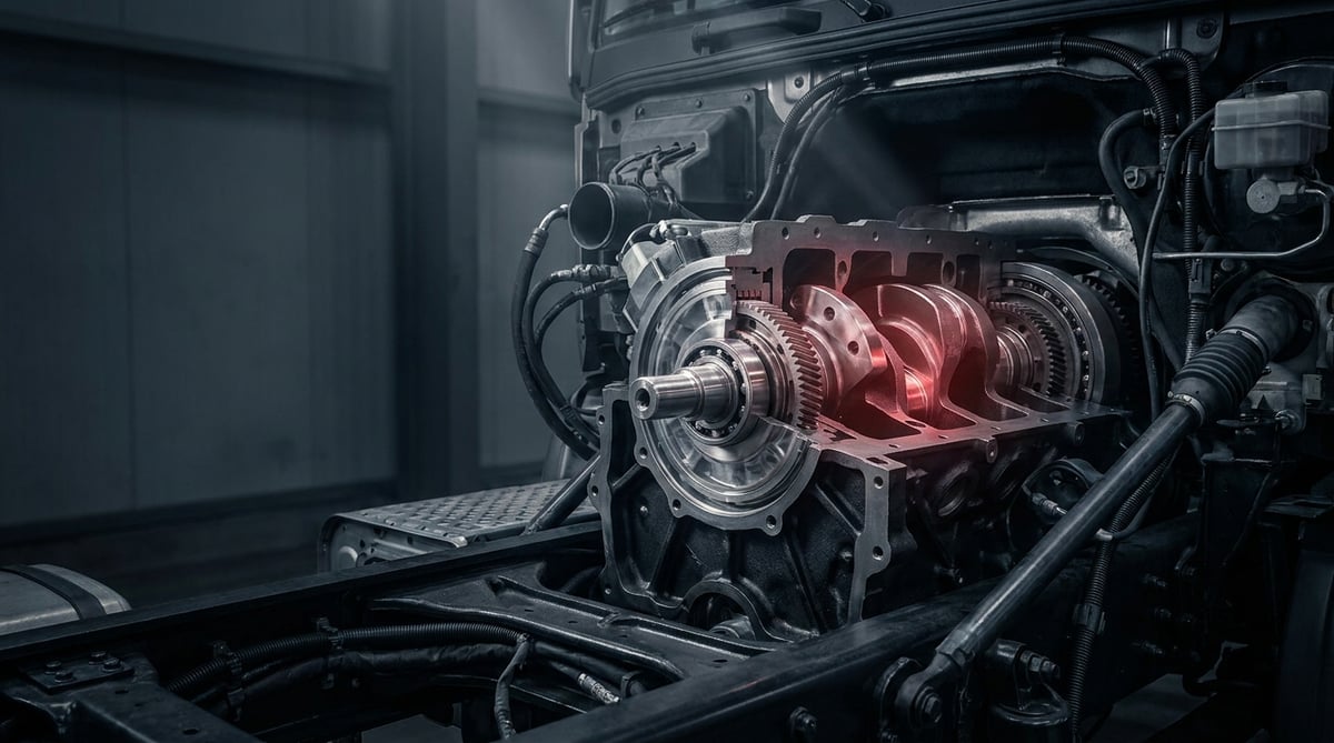
The air compressor is a component that runs quietly in a heavy commercial vehicle but keeps that vehicle off the road the moment it stops. Inside the compressor, the element that carries the greatest load is the crankshaft: it takes the drive from the engine, transmits it to the piston through the connecting rod, and at the same time absorbs the loads created by oil and air pressure. A significant portion of the complaints that reach the field as "the compressor is throwing oil," "it's not building air," or "there's a knock coming from the compressor" originate from a problem in the crankshaft bearings, the drive gear/pulley, or the key–taper connection. This guide was prepared to introduce the compressor crankshaft and drive assembly, diagnose the fault correctly, carry out the replacement by the book, and prevent the fault from recurring.
What Is the Compressor Crankshaft & Drive Assembly? Its Function and Operating Principle
The compressor crankshaft and drive assembly is the set — made up of the shaft, gear/pulley, bearings, seals, and connecting elements — that converts the rotary motion taken from the engine into the linear motion of the compressor piston, while also performing the bearing, sealing, and lubrication functions.
The operating principle is a scaled-down version of the engine's crank–connecting rod mechanism. The engine delivers torque to the compressor crankshaft through a gear, belt-pulley, or a direct coupling. As the eccentric journal (crank pin) on the crankshaft rotates, the connecting rod moves the piston up and down inside the cylinder. As the piston descends, air (or, in turbo-fed systems, pressurized air) is drawn in through the intake valve; as it rises, the air is compressed and sent through the discharge valve to the air dryer and from there to the air tanks. The main journals rotate on bearings; in most applications, engine oil is supplied under pressure to the compressor body and distributed to the journals through the oil galleries inside the crankshaft. The seals at the ends of the shaft prevent oil from escaping outward and air from leaking into the oil side.
The main elements that make up the assembly:
- Crankshaft (main body): Carries the main journals, the eccentric crank pin, the oil galleries, and the counterweights.
- Main bearings: Depending on the application, ball/roller bearings or plain (bushing/half-shell) bearings.
- Connecting rod and big-end bearing: The link from the crank pin to the piston.
- Drive element: Drive gear, belt pulley, or clutch/coupling hub.
- Connecting elements: Key (keyed type), taper hub, shaft nut/bolt, washer, and locking elements.
- Seals and O-rings: Front/rear shaft seal, cover gaskets.
- Axial adjustment elements: Shim, adjustment washer, circlip/retaining ring.
Drive types: gear, pulley, and clutched
In gear-driven compressors, the crankshaft takes its drive directly from the engine gear train; there is no synchronization loss, but the gear backlash and the assembly sequence are critical. In belt-pulley-driven types, the pulley tension and alignment impose radial load on the shaft; a tensioning fault directly affects the front bearing and seal life. In clutched (clutch / energy-saving) types, the compressor idles or disengages when there is no air demand; in these types, the condition of the hub and clutch surface is as important as the torque transmission at the shaft end.
Bearing arrangement: rolling-element and plain approaches
In small and medium-capacity compressors, rolling-element bearings are common; the oil requirement is low and friction is minimal, but they are sensitive to impact and vibration. In high-capacity types fed with pressurized oil from the engine, plain bearings are preferred; the oil film is load-bearing, so damage develops quickly when oil pressure or cleanliness deteriorates. The diagnostic logic in this guide is the same for both types: the triad of clearance + noise + oil consumption is read together.
Sealing and oil balance
One of the crankshaft's duties is to separate the oil side from the air side. A worn main bearing makes the shaft rotate with a runout of a few hundredths of a millimeter; the seal no longer seats properly, and the compressor begins to "throw oil." In the field, this is usually mistaken for a ring/cylinder fault, whereas the source is often bearing clearance. Likewise, excessive crankcase pressure (blow-by) or a clogged oil return line will make even a sound seal leak.
| Application / engine group | Typical drive form | Bearing tendency | Key concern in the crank assembly |
|---|---|---|---|
| Heavy-duty tractor unit, gear-driven single-cylinder compressor (Knorr-Bremse type/equivalent) | Direct from engine gear train | Plain + pressurized lubrication | Oil pressure and gear backlash |
| Truck/bus, twin-cylinder high-capacity compressor (Wabco type/equivalent) | Gear or coupling | Plain | Axial clearance, big-end bearing |
| North American heavy commercial compressor (Bendix type/equivalent) | Gear or belt-pulley (depending on type) | Rolling-element/mixed | Belt tension, front bearing load |
| Urban bus / energy-saving system | Clutched (clutch type) | Rolling-element | Hub seating, fatigue from frequent engagement |
| Light-to-medium commercial, compact compressor | Belt-pulley | Rolling-element (sometimes oil-free/low-oil) | Pulley alignment, seal life |
Fault Symptoms and Diagnosis
Crank assembly faults rarely appear on their own. In most cases, oil, heat, and clearance feed one another. The table below matches the most common symptoms encountered in the field with their possible causes and verification methods.
| Symptom | Possible Cause | Check / Verification |
|---|---|---|
| Rhythmic knock / metallic tapping from the compressor (increases with rpm) | Big-end bearing or main bearing clearance has grown; crank pin worn | With the engine at idle, listen at the body with a stethoscope; remove the compressor and measure the shaft's axial/radial clearance with a dial gauge |
| Oil carrying over to the air tanks, dryer cartridge filling up early | Shaft seal leaking, bearing runout damaging the seal, high crankcase pressure | Remove the discharge line fitting and inspect the oil film on the inner surface; check the oil return line and crankcase ventilation |
| Air pressure build-up time has lengthened / the compressor can't keep up | Valve group + secondarily an increase in dead volume from crank/connecting-rod clearance, cylinder wear | Tank empty - measure the build-up time to working pressure and compare with the service manual value; perform a leak test |
| Visible runout at the shaft end / pulley, belt constantly throwing off or burning | Front bearing wear, shaft bend, pulley hub not seated or key crushed | Measure shaft-end runout with a dial gauge; remove the pulley and inspect the taper/keyed surface and the keyway |
| Compressor body overheating, paint darkening / discoloration | Insufficient oil supply, bearing beginning to seize, running under continuous load (leak present) | Check oil supply line pressure and flow rate; look for air leaks in the system; measure surface temperature with a thermal camera/non-contact thermometer |
| Metal chips in the oil supply return / copper-bronze traces on the bearings | Bearing material worn away, unfiltered dirty oil circulating | Magnetic check of the oil return line and crankcase bottom; condition of engine oil and filter; open the compressor and inspect the bearing surface |
| Howl from the drive gear / tooth breakage | Incorrect gear backlash, excessive shaft axial clearance, alignment error | Gear backlash measurement (per manual value), contact-pattern check on the gear surface |
| Rotating/free noise from the compressor after the engine stops, or shaft play | Loss of the axial adjustment element (shim/circlip), coupling wear | Pull and push the shaft by hand to feel axial clearance, then verify with a dial gauge |
Rule out the system first, then go into the compressor
The most common cause of the "can't keep up with air" complaint is not the crank assembly but a leak in the system. Before removing the compressor: look for bellows/valve/fitting leaks with soapy water, check whether the air dryer is continuously purging, and measure the pressure regulator's cut-out pressure. A sound compressor will also behave as if "faulty" in a system with a constant leak, and will actually fail before long.
The correct order for diagnosing oil throw
Do not break the order when diagnosing oil throw: (1) engine oil level and crankcase ventilation condition, (2) whether the compressor oil return line is clogged, (3) intake line — excessive vacuum/pressure on a turbo-fed intake, (4) valve plate and rings, (5) shaft seal, (6) bearing clearance. Skipping the first three items and replacing the compressor directly is the number-one reason the same fault recurs a few thousand km later.
Measure without disassembling: measure the clearance instead of feeling it
The shaft's axial clearance and the runout at its end can, in most cases, be measured with a magnetic-base dial gauge even while the compressor is on the vehicle. Instead of saying it "seems to have play," take a measurement and compare the value with the limit in the service manual. If the limit is exceeded, an overhaul of the crank assembly or a complete compressor replacement comes into play; if it's within the limit, the fault must be sought elsewhere.
Standards and further reading
This subject is governed by the equipment rules for air-braked commercial vehicles. In the United States the federal air brake standard, FMVSS 121 (49 CFR 571.121) defines the reservoirs, protection and timing a compliant system must provide, and Europe applies the equivalent limits of UNECE Regulation No. 13. For further detail, see the illustrated reference guide at airbrakecompressor.com. Always confirm specific figures against the current regulation and the vehicle manufacturer service data.
Readers outside the United States should work from their own national framework: in the United Kingdom the braking system must be maintained under regulation 18 of the Road Vehicles (Construction and Use) Regulations 1986, and in India the governing rules are published by the Ministry of Road Transport and Highways.
Replacement / Installation Steps
- Confirm the fault and record it: Write down the clearance, runout, build-up time, and oil consumption values you measured. This is the only way to be able to make a comparison after replacement.
- Make the system safe: Disconnect the battery, drain the air tanks, and if it's a coolant-connected compressor, lower the antifreeze level and prepare a container to catch spillage.
- Remove the lines, labeling them: Discharge line, intake line, oil supply/return, water lines if present, and the regulator/clutch signal line. Cap the opening of each line; a single grain of sand that gets inside the compressor will finish off the new bearing.
- Remove the compressor: The compressor itself is not timed to the engine; however, since the drive gear is part of the engine gear train, verify per the manufacturer's instructions that the gear train marks are not disturbed during removal/installation. The compressor is heavy; do not try to hold it alone — use support/lifting.
- Inspect the drive assembly: Gear/pulley tooth surfaces, key and keyway, taper-surface contact pattern, shaft-end screw. A crushed key or a shiny/worn taper surface tells you the previous assembly was done loose — change not just the part but also the cause.
- Measure the crank assembly and decide: Main journal and crank pin diameters, bearing clearance, axial clearance, shaft runout, and the openness of the oil galleries. If the service limit is exceeded, the shaft + bearing set is renewed together; if the journal surface is scored/gouged, the shaft is absolutely not reused.
- Clean the seats and oil passages: Open the body bearing seats, the oil galleries, and the return hole with compressed air + a suitable cleaner. Scrape old gasket residue off without scratching the surface; leave no chips behind.
- Install the bearings and crankshaft: Fit the new bearings lubricated with clean oil, in the correct orientation and fully seated. On rolling-element types, assemble by heating/press — never by direct hammer blow — and always apply force through the correct race.
- Renew the seal and gaskets: Install the shaft seal with a suitable guide tool, without turning its lip inside out; lubricate the seal lip before installation. Always use new cover gaskets.
- Fasten the drive element by the book: Seat the key fully in its slot, free the taper surface of oil/grease, and tighten the shaft nut to the torque in the manual and, if applicable, the angle value. On pulley-driven types, check alignment with a straightedge/laser and set the belt tension with a tension gauge.
- Install, fill, and commission the compressor: Before connecting the oil supply line, make sure clean oil is coming from the line. After installation, run the engine at idle and check oil sealing, noise, and pressure build-up time; after a short road test, review the torque and sealing again.
Points to Watch (Common Mistakes)
- Fitting a bearing with a hammer: The impact leaves an invisible indentation (brinelling) in the ball race; the part is damaged before it even runs.
- Reusing the old key: A crushed key develops clearance again at the first load. The key and shaft nut must be renewed when the shaft is replaced.
- Installing the seal dry / turning its lip inside out: The lip burns on first operation, and the compressor throws oil immediately.
- Skipping the axial clearance adjustment: If the shim/circlip arrangement is disturbed, the gear contact shifts, bringing howling and tooth breakage.
- Setting belt tension by "pressing with your hand": An over-tight belt kills the front bearing and the seal; a loose belt overheats and eats the pulley.
- Wrong or dirty oil: The compressor shares the engine oil; a stretched oil change interval on the engine directly affects the compressor bearing.
- Not replacing the air dryer cartridge: A saturated cartridge returns moisture to the system; corrosion and valve failure also strain the crank assembly.
- Skipping the first check after installation: A short monitoring period should be carried out after installation; skipping the first check is one of the most frequently recurring assembly faults in VADEN field feedback (see the "Maintenance and Service Life" section for the detailed monitoring protocol).
Technical Values and Check Points
The values below are of a typical/general reference nature for heavy commercial vehicle air compressors. There can be significant differences between compressor type, manufacturer, and model year; when making a decision, always rely on the current service manual of the vehicle/compressor manufacturer.
| Parameter | Typical reference range | Note |
|---|---|---|
| System cut-out pressure | approximately 8.0–12.5 bar (≈115–180 psi) | Varies by regulator/EBS setting and market |
| System cut-in pressure | ~1.0–2.0 bar below the cut-out pressure | If the difference is too small, the compressor engages frequently and the assembly fatigues |
| Compressor oil supply pressure (working rpm) | generally the same order as engine oil pressure, typically ≥1.5–2.0 bar | Critical on plain-bearing types; the manual value governs |
| Discharge line air temperature (continuous) | typically in the 150–200 °C band; short-term peak values may be higher | Persistently high temperature is an indicator of carbonization and valve failure |
| Compressor body surface temperature (loaded operation) | typically ~80–130 °C | Marked deviation - leak, lubrication problem, or bearing seizure |
| Shaft axial clearance | typically on the order of 0.05–0.30 mm | The exact value and service limit are taken from the manual |
| Main bearing radial clearance (plain) | typically on the order of 0.02–0.10 mm | Measure the journal diameter and calculate the bearing clearance |
| Shaft-end runout (run-out) | generally targeted below 0.05 mm | High runout - seal and belt life shortens |
| Drive gear backlash | typically on the order of 0.05–0.25 mm | The value in the engine gear train manual is binding |
| Tank fill (build-up) time test | compared with the time defined in the vehicle manual; clearly exceeding the manual time (in practice on the order of ~20%) requires investigation | First rule out leaks, then evaluate the compressor |
In tightening torques, the measurement is as important as the part itself. The table below is intended only to give an order of magnitude:
| Connection | Typical torque order | Warning |
|---|---|---|
| Shaft-end nut (pulley/gear hub) | typically 80–200 Nm, with an added angle tightening on some types | Highly variable per type — the manual is mandatory |
| Cylinder head bolts | typically 25–50 Nm, staged and crosswise sequence | The sequence and stage are not skipped |
| Crankcase/bearing cover bolts | typically 15–35 Nm | Over-tightening distorts the seat geometry |
| Connecting-rod cap bolts | typically 20–45 Nm (single-use on most types) | If not reusable, always renew |
| Compressor body mounting bolts (to engine) | typically 40–90 Nm | The flange surface must be clean and flat |
Quick field checklist:
- Tanks empty - measure the build-up time to cut-out pressure and compare with the manual.
- With the engine at idle, listen to the compressor with a stethoscope: rhythmic knock = suspect the bearing/connecting rod.
- Remove the discharge fitting and inspect the oil film on the inner surface; wet oil = oil carryover.
- Measure the shaft-end and pulley runout with a dial gauge.
- Check the belt tension with a gauge; verify the alignment with a straightedge.
- Check the air dryer cartridge age and its purging behavior.
- Verify that the oil return line flows freely.
Maintenance and Service Life
The service life of the compressor crank assembly depends as much on the quality of the environment it operates in as on the quality of the part. With clean oil, clean air, correct tension, and a leak-free system, the assembly gives no trouble for many years; when one of these deteriorates, the service life shortens rapidly. Because the compressor in a heavy commercial vehicle runs with every turn of the engine, the only way to use it "without wearing it out" is to reduce unnecessary engagement.
- Engine oil discipline: The compressor uses the engine oil in most applications. A stretched oil change interval directly shortens the crank bearing's life. Stick to the manufacturer's interval and the correct specification.
- Air dryer cartridge: Generally replaced once a year or at the km interval in the vehicle manual. Moisture is the quietest enemy of the system and the compressor.
- Intake filter/line: A clogged filter runs the compressor under vacuum and increases oil intake. Check it together with the engine air filter.
- Leak hunt: Once a month, look for bellows, valve, and fitting leaks with soapy water. A continuously running compressor = short life.
- Belt and alignment: On pulley-driven types, periodically check the belt condition and tension; replace a cracked/glazed belt without waiting.
- Tank draining: Regularly drain water from the drain valves under the tank; as water leaks back, corrosion begins.
- Noise monitoring: Don't postpone a newly appearing knock or howl. Bearing clearance caught early is solved with an overhaul; if postponed, the shaft and the body go together.
- Post-overhaul monitoring: In the first few hundred kilometers following installation (in practice on the order of ~500–1,000 km), sealing and torque should be checked, and at the first service, oil return and build-up time should be measured again. A significant portion of the recurring assembly faults in VADEN field feedback stems from skipping this early check.
In short: the crank assembly is not a "fit-and-forget" part. Every replacement made without eliminating the conditions that cause the fault (dirty oil, moisture, leaks, wrong tension) is a deferred repeat of the same fault. The triad of correct diagnosis + by-the-book assembly + regular maintenance turns the compressor into a reliable element throughout the vehicle's life.
The VADEN ORIGINAL Compressor Crankshaft & Drive Assembly product family covers crankshafts, crankshaft flanges and crankshaft repair kits, connecting rods and connecting rod bearings, bearing and bushing sets, drive gears, drive shafts and coupling sets, along with bolt–nut hardware and gasket kit groups for heavy commercial vehicle air compressors. The products are catalogued according to the shaft-end form, journal dimension, and bearing arrangement of the common OE compressor types (Knorr-Bremse, Wabco, Bendix, etc. type/equivalent). To find the reference suitable for your vehicle, verify the OE cross number, or select an overhaul kit, search for your compressor type in the Compressor Parts catalog, or reach our technical team together with the compressor body number.
Related categories: Crankshaft · Crankshaft Flange · Crankshaft Repair Kit · Drive Shaft · Gear · Pinion Kit
Related technical guides: Compressor Piston-Ring & Connecting Rod: Repair Guide · Truck Air Compressor Overhaul Kit: Head, Valve Plate, Gasket · Compressor Valve & Unloader: Fault, Replacement & Care Guide · Compressor Cooling Plate & Water Cooling: Faults, Repair & Care
Application and compatibility: Vehicle compatibility catalogue · Engine compatibility catalogue
Main guide: Air Brake Compressor: Faults, Replacement & Maintenance Guide
Tags
Frequently Asked Questions
- Should the compressor crankshaft be replaced, or should a complete compressor be fitted?
- The decision is based on measurement. If the journal surfaces are sound, the body bearing seats undamaged, and the clearance has only just approached the service limit, an overhaul of the crankshaft + bearing set is the economical and correct solution. If there are scores/gouges on the journals, wear in the body, or wear in more than one group (valve + rings + bearing), a complete compressor is safer. On high-km vehicles, total cost and downtime should also be taken into account.
- Why does the compressor throw oil — are the rings always to blame?
- No. The most common causes of oil carryover are, in order: a clogged/restricted oil return line, high crankcase pressure, an intake line problem, followed by the valve plate, the rings, and the shaft seal. Clearance in the crank bearing also makes the shaft rotate with runout, damaging the seal and letting oil leak. That is why the line and crankcase ventilation must be ruled out before blaming the rings.
- There's a knocking noise from the compressor — can I keep driving the vehicle?
- Not recommended. A rhythmic knock usually indicates that the big-end or main bearing clearance has grown. Continuing at this stage can cause the bearing to disintegrate completely, mixing metal particles into the oil circuit and leading to more severe damage. Once you've confirmed the noise, have it checked as soon as possible.
- How long does the compressor crankshaft last?
- It would be wrong to give a definite km figure; the usage profile is the determining factor. An assembly running with clean oil, regular dryer maintenance, and a leak-free system is long-lived. In an assembly that idles due to a constant leak, is fed with dirty oil, or is strained by an over-tight belt, the service life shortens noticeably. For a service-life target, the vehicle manufacturer's maintenance program should be taken as the basis.
- Are the compressor crankshaft and the engine crankshaft the same thing?
- The principle is the same, but the scale and role differ. Both convert rotary motion into linear motion; however, the compressor crankshaft receives the engine's drive (whereas the engine crankshaft produces the power), is much smaller, and generally manages a single/twin-cylinder mechanism. Their replacements and diagnoses are evaluated independently of one another.
- What information should I have ready to avoid getting the wrong part?
- The most reliable approach is to go by the manufacturer/OE number on the compressor body. Add to it the vehicle make-model-engine type, model year, drive form (gear/pulley/clutched), shaft-end form (taper-keyed-flanged), and the shaft diameter if available. Ordering with only "X brand tractor unit" information is risky, since more than one compressor type can be used on the same vehicle.
- When the compressor crank assembly is replaced, which other parts should be renewed along with it?
- Standard practice: the main bearing set, the big-end bearing, the shaft seals, all gaskets, the key, and the shaft nut. These seal, gasket, and bearing elements are found in the Compressor Parts category. Single-use bolts (especially the connecting-rod cap) are not reused. In an oil-throw case, the air dryer (dryer purge valve) cartridge should also be replaced, the oil return line cleaned; on pulley-driven types, the belt and the tensioning element should also be reviewed.
- Do an aftermarket crankshaft and drive assembly deliver the same performance as OE?
- What matters is not the "aftermarket" label but the production and verification quality. If the material, surface hardness, journal grinding quality, oil gallery cleanliness, and dimensional tolerances meet the OE specification, no difference in performance and service life is expected. What's critical is that the part matches the correct type and that the assembly is done by the book — a wrongly matched part is short-lived regardless of the brand it comes from.
- Air pressure builds up slowly - is the compressor always the culprit?
- No; the most common cause is a leak in the system. Before removing the compressor, look for bellows, valve and fitting leaks with soapy water, check whether the air dryer is purging continuously, and measure the pressure regulator's cut-out pressure. A sound compressor behaves as if faulty in a constantly leaking system, and because it is forced to run non-stop it will genuinely fail before long.
- Why does belt tension matter so much on a pulley-driven compressor?
- Because the tension puts radial load straight onto the shaft. An over-tight belt kills the front bearing and the shaft seal; a loose belt slips, overheats and eats the pulley. Set the tension with a tension gauge rather than by pressing with your hand, and verify the alignment with a straightedge or laser. Replace a cracked or glazed belt without waiting; take the exact value from the service manual.
Related Articles
Compressor Connection Hardware: Faults, Replacement, Care
How truck air compressor adapters, bolts, plugs and hoses fail, how to diagnose leaks and blockages, replace them correctly and extend service life.
Compressor Repair and Gasket Kit: Faults, Replacement, Care
Diagnosing air compressor gasket failure on trucks: choosing the right repair kit scope, preparing surfaces, torquing correctly and extending seal life.
Compressor Cooling Plate & Water Cooling: Faults, Repair & Care
Diagnose, replace and maintain the heavy-truck air compressor cooling plate and water cooling: symptoms, internal-leak testing, torque values and FAQ.


