Engine Piston & Liner: Faults, Replacement and Maintenance
Piston and liner guide for heavy truck diesel engines: fault symptoms, liner protrusion and shim selection, step-by-step replacement and maintenance.
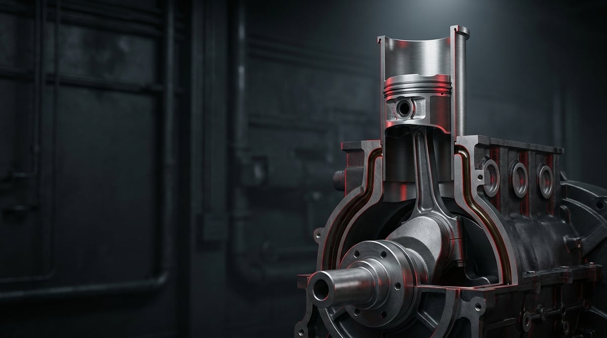
When blue smoke starts coming from the exhaust, when the oil level drops noticeably between two service intervals, or when strong "blow-by" comes out of the crankcase breather, the first thing that comes to a technician's mind is the piston–ring–liner trio. On heavy commercial vehicles this trio is the most heavily loaded area of the engine and the one that demands the most expensive repair; that is why the decision to "pull the liners" must be based on correct measurement, and the measurement itself must be taken in the correct order. This guide covers pistons, liners and liner protrusion shims (adjusting washers) on wet-liner heavy commercial diesel engines in workshop language: how the fault is identified, which measurement is taken where, how the shim is selected, and which assembly mistakes force you to strip the engine down a second time.
E-E-A-T note: This document has been prepared by the VADEN technical team, which works on heavy commercial vehicle engines and compressed air systems. The numerical values given here are general reference ranges; for exact values such as liner protrusion, piston protrusion, ring end gap, piston-to-liner clearance and torque/angle figures, the engine manufacturer's current OE service manual must always be taken as the authority. Last updated: September 2026.
Component sizing is based on the relevant international standard family (ISO/EN/DIN/SAE) and the manufacturer OE specification.What Are Engine Pistons & Liners? Function and Operating Principle
The engine piston and liner group is the mechanical set consisting of the liner that forms the cylinder surface in which the piston travels, the piston that transfers combustion pressure to the crankshaft through the connecting rod, and the shim (adjusting washer) that sets the seating height of the liner in the block — together delivering the engine's compression and power output.
The operating principle looks simple, but the tolerances are unforgiving. As the piston moves up and down inside the liner dozens of times per second, it performs three jobs at once: keeping the combustion chamber sealed, converting combustion pressure into mechanical motion, and transferring a significant portion of the heat accumulating in its crown through the rings into the liner and from there into the coolant. The liner, in turn, is a replaceable surface that carries this friction and heat load and sacrifices itself rather than the block when it wears. Wet liners (liners in direct contact with the coolant) are widespread on heavy commercial vehicles; thanks to this, the engine can be overhauled after hundreds of thousands of kilometres without replacing the block.
The shim is the part most people underestimate, yet it actually decides the fate of the job. How far the liner stands above the block face (liner protrusion) determines how much the cylinder head gasket will be compressed. If protrusion is too low, the gasket is not clamped enough and combustion gas escapes into the coolant; if it is too high, the liner flange cracks or the gasket is crushed. The shim is the thin steel washer placed under the liner flange to set this protrusion to hundredths of a millimetre.
- Piston: Aluminium alloy, or steel/composite bodied on high-load engines; it has a combustion bowl in the crown, ring grooves and a pin boss in the body.
- Ring set: Usually two compression rings (the first mostly a keystone/trapezoidal type) and one oil control ring; sealing and oil control take place here.
- Piston pin and circlips: The hardened pin connecting the piston to the connecting rod, plus its retaining clips.
- Liner: Centrifugally cast grey iron or nitrided; the bore is honed and the upper flange seats on the block.
- Liner O-rings / seal kit: On wet liners, the lower sealing elements that separate the water jacket from the crankcase.
- Shim (adjusting washer): A thin washer produced in steps starting from 0.05 mm that sets the protrusion.
Wet Liner, Dry Liner and Parent-Bore Block: The Difference
With a wet liner the coolant contacts the outer surface of the liner directly; this gives the best heat transfer and the easiest serviceability, and it is the preferred solution on most heavy commercial diesels. In return, O-ring sealing in the lower area becomes critical. A dry liner is an interference fit in the block bore and has no contact with coolant; it is generally seen in repair applications or on light commercial vehicles. On parent-bore blocks the cylinder surface is the block material itself; when it wears, the block is machined and oversize pistons are used, which requires workshop capacity.
The Role of the Rings: Sealing or Oil Control?
The first compression ring holds most of the combustion pressure; pressure gets behind the ring and pushes it towards the liner, so the seal reinforces itself. The second ring manages both the remaining pressure and the oil carried upwards. The oil control ring scrapes excess oil off the liner wall back into the crankcase, leaving only a lubricating film a few microns thick behind it. Most oil consumption complaints come down to this third ring or the groove it sits in; not every case of oil consumption means "the liners are finished".
Why Is There a Shim? The Logic Behind Liner Protrusion
When the cylinder head is torqued, the gasket is clamped between the block face and the head. If the liner flange stands a few hundredths of a millimetre above the block face, the gasket sees its highest surface pressure exactly around the liner mouth and combustion gas cannot get past this barrier. This height differs by engine type and is influenced by the combined tolerance of liner, block counterbore and gasket. The shim exists to close this tolerance; using a washer, spacer or sheet metal piece of arbitrary thickness leads straight to a burnt gasket.
Piston Protrusion and Head Gasket Thickness Selection
There is a second measurement that is often confused with liner protrusion but is independent of it: piston protrusion. With the piston brought to top dead centre (TDC), you measure how far the piston crown rises above the block deck face. On many heavy commercial diesel engines the cylinder head gasket thickness is selected in steps according to this piston protrusion; the manufacturer usually offers two or three thickness classes (mostly marked by the number of holes/notches on the gasket edge or by a colour code), and whichever band the measured protrusion falls into determines the class fitted.
The logic is this: piston protrusion determines the clearance remaining between the piston crown and the head face at TDC (squish/deck clearance) and therefore the effective compression ratio. If a thin gasket is fitted to an engine with large protrusion, the safety distance between piston and head/valves is dangerously reduced; if a thick gasket is fitted where protrusion is small, the compression ratio falls, cold starting becomes harder and emission behaviour deteriorates. For this reason the gasket class must be re-verified whenever a change is made on the piston, connecting rod, liner or block side.
The measuring practice, in short: in each cylinder the piston is brought to TDC, the dial gauge is zeroed on the block deck face, and readings are taken from two points on the piston crown perpendicular to the pin axis (or from the measuring points indicated by the manufacturer); the average of the readings is that cylinder's protrusion. For the whole engine the highest value is generally decisive and a single gasket class is used across all cylinders. On heavy commercial diesels typical piston protrusion values lie in a narrow band roughly between a few hundredths and a few tenths of a millimetre; the step limits and gasket class table are entirely specific to the engine family and must be read from the OE service manual. When buying a "piston + liner + shim" set, remember that these two protrusion measurements are taken separately: the shim addresses liner protrusion, while the gasket class addresses piston protrusion; one does not substitute for the other.
| Measurement | What does it set? | Adjusting element |
|---|---|---|
| Liner protrusion | Surface pressure on the gasket, gas sealing | Shim (adjusting washer) placed under the liner flange |
| Piston protrusion | Piston-to-head clearance at TDC, effective compression ratio | Stepped cylinder head gasket thickness (class selection) |
| Engine family (application) | Typical liner type | Approximate bore diameter | Service note |
|---|---|---|---|
| Mercedes-Benz OM 457 / OM 460 type (Actros, Travego, Tourismo) | Wet liner, flanged | ≈ 128 mm class | Protrusion is set with shims; replacing piston+liner+rings as a set is recommended. |
| Mercedes-Benz OM 906 type (Atego, Axor, bus) | Wet liner | ≈ 102 mm class | Mid segment; the lower liner O-ring kit must always be renewed. |
| Mercedes-Benz OM 926 type (Atego, Axor, bus) | Wet liner | ≈ 106 mm class | Not the same bore as the OM 906; verify the diameter by engine number before ordering. |
| MAN D20 / D26 type (TGA, TGX, TGS) | Wet liner | ≈ 120–126 mm class | Cleanliness of the lower O-ring groove and block counterbore is critical. |
| DAF MX type (XF, CF) | Wet liner | ≈ 130 mm class | High combustion pressure; pay attention to protrusion difference tolerance. |
| Volvo / Renault D-series type (FH, FM, Premium) | Wet liner | ≈ 131 mm class | Piston cooling oil jets must be checked. |
| Iveco Cursor type (Stralis, S-Way) | Wet liner | ≈ 125–135 mm class | Head bolts are angle-tightened; they may be single-use. |
Part number verification: The bore and type information above is for guidance only. Within the same engine family, different piston crowns, different ring heights and different liner flange thicknesses may be used depending on emission level (Euro 3/4/5/6), production year and turbo/EGR configuration. Engines with similar names (for example OM 906 and OM 926) do not share the same bore. Before ordering, verify via the engine number and OE part number; also make sure to read the number stamped on the part you have removed.
Fault Symptoms and Diagnosis
Piston-liner failure rarely appears all at once; it usually starts with oil consumption, continues with crankcase pressure, and reveals itself through power loss and smoke. The aim in diagnosis is to determine whether the problem really is in the cylinder group or in a cheaper item such as the turbocharger, valve stem seals, injectors or the head gasket.
| Symptom | Possible Cause | Check / Verification |
|---|---|---|
| Blue smoke from the exhaust, rising oil consumption | Fatigued oil control ring, contaminated ring groove, worn-away liner hone | Measure oil consumption per km; first rule out turbo oil leakage and valve stem seals, then carry out a compression/leak-down test. |
| Strong blow-by from the crankcase breather | Ring wear, broken ring, liner wear | Loosen the oil filler cap with the engine hot and observe the blow-by; for a definitive distinction, run a cylinder leak-down test. |
| Compression difference between cylinders | Ring/liner damage in a single cylinder, or valve leakage | Run a compression test; add a little oil to the low cylinder and repeat — if the value rises, the problem is on the ring/liner side. |
| Knocking on cold running that fades as it warms up | Piston skirt wear, excessive piston-to-liner clearance ("piston slap") | Listen cylinder by cylinder on the block side face with a stethoscope; after strip-down, measure ovality and taper of the liner bore. |
| Bubbles in the expansion tank, dropping level, water pressure | Insufficient liner protrusion, wrong shim, gasket leakage, cracked liner flange | Cooling system pressure test and exhaust gas leak (CO2) test; when the head comes off, re-measure protrusion with a dial gauge. |
| Water in the oil, milky coffee appearance | Damaged lower liner O-ring, cracked liner body, cavitation perforation | Inspect the sump oil; pressurise the block water jacket and look for seepage at the liner base. |
| Power loss, black smoke, increased fuel consumption | Loss of compression, worn liner, injector disturbing combustion | First check injector return flow and air filter/boost pressure; if these are clean, move on to compression measurement. |
| Pitting on the outer surface of the liner | Cavitation (lack of coolant additive, wrong antifreeze) | After strip-down, inspect the liner's outer wall visually; check coolant additive concentration and pH. |
Compression Test or Leak-Down Test?
A compression test is quick and shows the difference between cylinders, but it does not tell you where the loss comes from. In a cylinder leak-down test, compressed air is fed into the cylinder and you listen for where the sound comes from: from the intake manifold means the intake valve, from the exhaust means the exhaust valve, from the crankcase breather means rings/liner, and bubbles from the radiator mean a gasket or protrusion problem. Performing both tests together before deciding prevents unnecessary engine strip-down.
Measuring Oil Consumption Correctly
"It's drinking oil" is a subjective statement. The correct method is to record the fill quantity after an oil change, log the oil added over a defined distance, and calculate consumption in litres per thousand kilometres. On modern heavy commercial diesels, consumption is generally at the level of a few thousandths of fuel consumption; an engine clearly above this band should be investigated. Turbo oil seals, valve stem seals and a blocked crankcase breather system produce the same symptom and are cheaper repairs.
Measurement Discipline Before Strip-Down
Do not rush to pull the liners as soon as the head comes off. First measure and record the liner protrusion in each cylinder with a dial gauge, and measure the liner bore at top dead centre level and in the lower area, both along and perpendicular to the axis, to establish taper and ovality. Also record the thickness class marking of the removed gasket (number of holes/notches, colour code) — it will be your reference when comparing the new gasket class against the piston protrusion measurement. These values are the only objective evidence that tells you whether the problem is wear or an assembly error.
Further reading
For a plain-language technical overview of this subject, see the reference article on Wikipedia. Always confirm specific figures and procedures against the vehicle manufacturer service data.
Replacement / Installation Steps
Personal protective equipment and safety: Park the vehicle on level ground, apply the parking brake, chock the wheels and disconnect the battery terminal. Do not open the cooling system before the engine has cooled completely — pressurised hot coolant causes serious burns. Gloves, safety glasses and safety footwear are mandatory. The piston-conrod assembly and the cylinder head are heavy; use suitable slings and a hoist for lifting, do not attempt to lift by hand. Collect waste oil, antifreeze and cleaning solvents in accordance with regulations; do not create sparks in a solvent-laden environment.
- Preparation and draining: Drain the coolant and engine oil into suitable containers. Read and save the vehicle's engine fault records; you will compare them with your findings after strip-down. Clear the work area of dust — cylinder group assembly is a cleanliness job.
- Upper group removal: Remove the injectors, rocker mechanism, push rods and cylinder head following the manufacturer's loosening sequence (usually from outside inwards, in stages). On most heavy commercial engines the head bolts are angle-tightened and single-use; plan for new ones.
- Measurement and marking: Before removing the liners, measure the protrusion in each cylinder and write it down. Mark the rod caps, the liners and any existing shims according to cylinder number. Nothing that will be reused may end up in the wrong position.
- Removing the piston-conrod assembly: Clean the carbon ridge in the upper area of the liner with a suitable ridge reamer, remove the rod cap and lift the piston-conrod assembly out from above. Fit protective sleeves over the rod body so the crank journal and the liner surface are not scored.
- Liner removal and counterbore cleaning: Pull the liners with a suitable puller; forcing them with a chisel or lever ruins the block counterbore. Completely clean the liner seating surface, the O-ring grooves and the water jacket on the block of scale, corrosion and gasket residue. The seating face must be mirror clean.
- Block inspection: Check the flatness of the block deck face with a straight edge and feeler gauge. Measure the liner counterbore depth; if there is wear or erosion, grinding/machining may be required. If there are cavitation marks, the cooling system chemistry must also be corrected.
- Dry trial fit and shim selection: Seat the new liners in their counterbores without O-rings and without oil, press down lightly from above and measure the protrusion with a dial gauge. Readings are taken from at least four points around the liner. If the value is below the manufacturer's band, add a shim of suitable thickness; if it is above, the liner/counterbore must be checked. Also keep the protrusion difference between cylinders of the same engine tight.
- Liner installation: Once the shim selection is finalised, remove the liner, lightly lubricate the lower O-rings with the lubricant specified by the manufacturer (often a special assembly soap or clean engine oil), fit them into their grooves without twisting, and press the liner home in one movement without tilting it. After installation, measure and record the protrusion once more.
- Secure the liners with clamps (do not skip this): Once the liners are seated, keep them pressed onto the block with liner clamps / retaining tools until the cylinder head is fitted and torqued. On a wet liner, with no head fitted, the only thing holding the liner in place is the friction of the lower O-rings; if the crankshaft is turned in this state, piston friction can lift the liner a few millimetres, and as the liner settles back the lower O-ring slips out of its groove and gets cut or twisted. The result is water in the sump oil at first start and a second strip-down of the engine — this is the most common mistake made in the field. Fit a clamp to every cylinder and remove the clamps only after the head bolts have been torqued through the first stage. If you have no clamping tool, do not turn the crankshaft under any circumstances.
- Piston and ring installation: Fit the rings onto the piston with ring pliers, with the end gaps staggered at the angles specified by the manufacturer; the "TOP" mark must face upwards. Verify the ring end gaps with a feeler gauge inside the liner. The arrow/mark on the piston crown must be oriented correctly relative to the flywheel or the combustion chamber.
- Installing the piston-conrod assembly: Lubricate the piston skirt and the liner surface with clean engine oil, compress the rings with a ring compressor and gently push the piston in using a wooden handle. Lubricate the rod bearings, fit the caps according to their numbers and apply torque + angle values in stages. If you need to turn the crankshaft at this stage, make sure the liner clamps are still fitted.
- Piston protrusion measurement and gasket class: Once all pistons are fitted, bring the piston in each cylinder to TDC and measure piston protrusion with a dial gauge. Select the appropriate cylinder head gasket thickness class from the manufacturer's table according to the highest value; verify the marking on the gasket (number of holes/notches or colour code) before fitting it.
- Head installation and first start: Fit the selected new cylinder head gasket dry and the right way round, torque the head using the manufacturer's tightening sequence and stages; remove the liner clamps once the first stage is complete. Fill with oil and coolant and bleed the system. On first start, confirm that oil pressure builds, check for leaks at idle, and do not work the vehicle at full load during the run-in period.
Points to Watch (Common Mistakes)
Shim selection is never done by guesswork. The "fit the same as the old one" approach is the most common and most expensive mistake. There can be a few hundredths of a millimetre difference between the flange thickness of the new liner and the old one; the block counterbore has also worn over the years. Protrusion must be re-measured for every liner and the shim selected accordingly. Stacking two washers of different brands or thicknesses to "hit the setting" is likewise unacceptable.
Do not turn the crankshaft without clamps. Turning the crankshaft with the liners fitted but the cylinder head not yet installed moves the liner out of position on wet-liner engines and cuts the lower O-ring. The damage is invisible during assembly; it shows itself as water in the oil after the first start. A liner clamp is a cheap tool — a second strip-down is not.
Do not reuse head bolts. On the majority of heavy commercial engines the cylinder head bolts are angle-tightened (torque-to-yield) and undergo permanent elongation at every removal. A reused bolt will not deliver the expected clamping force even if you apply the correct torque, and the gasket burns before long. Check the elongation limit against the length dimension given by the manufacturer, and replace if in doubt. The same rule applies to connecting rod cap bolts/nuts in most applications.
- Spreading rings by hand: Without ring pliers the ring is permanently distorted, the end gap and seating are ruined, and the engine burns oil from day one.
- Not washing the hone surface: Honing residue and preservative oil on new liners must be cleaned with hot soapy water and a clean cloth. Wiping with solvent alone leaves abrasive particles in the grooves.
- Fitting the O-ring dry or with the wrong lubricant: A dry O-ring twists or gets cut during installation; the wrong oil swells the material and eventually causes a coolant leak.
- Not cleaning the block counterbore thoroughly: A single piece of gasket or scale crust left in the counterbore falsifies the protrusion measurement and spoils the seating of the liner.
- Selecting the gasket class without measuring: Fitting a gasket of "the same class as the old one" without measuring piston protrusion means the wrong compression ratio or insufficient piston-to-head clearance if the piston or connecting rod has been changed.
- Getting the piston orientation wrong: In most piston designs the combustion bowl and the pin axis are offset from centre; a piston fitted the wrong way round causes knocking and rapid wear.
- Skipping the coolant additive: On heavy commercial vehicles the outer surface of the liner is exposed to cavitation; if the additive/antifreeze ratio specified by the manufacturer is not maintained, even a new liner can be perforated within a few years.
- Using mixed sets: Piston, rings and liner are a set manufactured to match each other; the service life of a cylinder group assembled from parts gathered from different sources is unpredictable.
- Skipping run-in: Running the engine at full load immediately after repair prevents the rings from bedding into the liner.
Technical Values and Inspection Points
The values below are general reference ranges commonly encountered on heavy commercial diesel engines. They vary by engine family, bore diameter and emission level; for the definitive figure, consult the service manual.
| Inspection point | Typical / general reference range | Note |
|---|---|---|
| Liner protrusion | Generally in the 0.02 – 0.15 mm band | A narrow sub-band is defined per engine family; the manual value is authoritative. |
| Protrusion difference between cylinders | Typically must not exceed 0.02 – 0.04 mm | If the difference between adjacent cylinders is large, the gasket is clamped unevenly. |
| Shim thickness steps | Usually in 0.05 mm increments (0.05 / 0.10 / 0.15 / 0.20 mm) | A single shim is used; stacking is not permitted. |
| Piston protrusion (relative to block face at TDC) | Narrow band specific to the engine family; generally between a few hundredths and a few tenths of a mm | The stepped gasket class is selected according to this measurement; limit values come only from the OE table. |
| Liner bore ovality / taper | Service limit typically 0.05 – 0.10 mm | The highest wear is seen in the top dead centre area. |
| Piston-to-liner clearance | Approximately 0.08 – 0.25 mm (depending on bore) | Measured at the skirt, perpendicular to the pin axis. |
| 1st compression ring end gap | Approximately bore × 0.003 – 0.005 (roughly 0.40 – 0.70 mm at 128 – 135 mm bore) | Scales with bore; the value drops on smaller-bore engines. Seat the ring squarely in the liner and measure with a feeler gauge. |
| Oil control ring end gap | Approximately 0.25 – 0.60 mm | An excessively tight gap makes the ring bind when hot and score the liner. |
| Ring groove side clearance | Approximately 0.04 – 0.12 mm | The measuring method differs on keystone rings; refer to the manual. |
| Compression pressure (on cranking) | Approximately 22 – 35 bar (≈ 320 – 500 psi) | The difference between cylinders matters more than the absolute value (typical limit around 10%). |
| Hone cross-hatch angle / surface roughness | Approximately 40° – 60°, Ra 0.4 – 0.8 µm band | Plateau honing speeds up ring bedding. |
| Coolant operating temperature | Approximately 80 – 95 °C | Continuous operation in the upper band accelerates liner wear. |
| Piston crown operating temperature | Typically areas above 300 °C | It must be verified that the piston cooling jets are open. |
Torque values differ greatly between engine families. The table below is only intended to show the method applied; for the actual figures the manual is authoritative.
| Joint | Typical application method | Warning |
|---|---|---|
| Cylinder head bolts | Staged pre-torque + angle tightening in the specified sequence (e.g. 2 angle stages) | Single-use in most applications; the sequence and stages cannot be skipped. |
| Connecting rod cap bolts / nuts | Pre-torque + angle tightening | Bearings must be lubricated and bolt threads clean; single-use in many applications. |
| Main bearing bolts | Staged torque, sequence from centre outwards | Free rotation of the crankshaft is checked at every stage. |
| Piston cooling jet screws | Low torque, generally in the 15 – 30 Nm band | Overtightening distorts the jet angle and can cut off piston cooling. |
Measuring tip: When measuring liner protrusion, zero the dial gauge on the block deck face and take readings on the liner flange at the 12, 3, 6 and 9 o'clock positions. A single-point measurement hides a slightly tilted liner. While measuring, use a bridge tool to press the liner down with a uniform force from above; a value obtained by pressing by hand is not reliable. The same dial gauge setup is also used to read piston protrusion with the piston at TDC.
- Check the block seating face for corrosion, nicks or residue with a clean cloth and a light, not with your finger.
- Measure the flange thickness of the new liner with a micrometer and compare it with the old one; if there is a difference, the shim decision changes accordingly.
- Measure the ring end gap separately in each cylinder; there can be small differences between liner bores.
- If the piston skirt shows a bright rub mark or one-sided wear, have the connecting rod checked for bend.
- Pitting (cavitation) marks are looked for on the outer wall of the liner, on the water side; not on the piston skirt. If these marks are present on the liner exterior, the coolant chemistry must also be corrected.
- Monitor and record oil pressure, coolant temperature and crankcase blow-by during the first 30 minutes after repair.
Maintenance and Service Life
Used correctly, the piston and liner are the longest-lived group in the engine; on heavy commercial vehicles, first-life figures of hundreds of thousands of kilometres are seen, and well-maintained tractor units approach a million kilometres. What determines service life is not so much the part itself as the quality of the oil, air and coolant reaching it. Most wear occurs during the cold-start minutes when the lubricating film breaks down, and when unfiltered dust enters the engine.
- Oil and oil filter: Use oil of the viscosity and specification stated by the manufacturer and do not extend the change interval. Contaminated oil carries abrasive particles straight onto the liner surface.
- Air filter and intake tract sealing: A small leak at a hose connection downstream of the filter renders the filter completely pointless and wears the liner within a few thousand kilometres. Dust wear generally leaves a bright, scratched surface in the upper liner area.
- Cooling system chemistry: Measure the antifreeze/additive ratio regularly. In a system with weakened cavitation protection, the liner's outer surface is perforated locally and water gets into the oil.
- Crankcase ventilation: A blocked breather raises crankcase pressure and pushes oil out past seals and rings; many faults believed to be "worn liners" are actually this.
- Injector and turbo health: A dripping injector washes the oil film off the liner wall with fuel; a turbo that leaks oil feeds the cylinder group with soot and oil and leads to ring sticking.
- Idling and cold-start habits: During long idling, combustion temperature drops, soot builds up and the ring grooves coke up. Warming the engine gradually before loading it is the cheapest way to extend service life.
No matter how well the engine is maintained, wear is inevitable at high mileage. The correct approach is to monitor consumption and crankcase pressure regularly and turn the repair into a planned overhaul. Piston damage that strikes on the road means several times the cost and lost days of a planned cylinder group renewal.
VADEN ORIGINAL carries the liner protrusion shims (adjusting washers) needed for this job as stocked items in its own catalogue, in the Engine Piston & Liner category. The shim steps are grouped by engine application; when choosing the right step we recommend verifying via the engine number and OE reference, and following the measurement discipline in this guide during assembly. Draw up the rest of the parts list before the engine comes apart: cylinder head bolts and, in most applications, connecting rod cap bolts/nuts are angle-tightened (torque-to-yield) and single-use; note these down from the outset along with the lower liner O-ring kit and the cylinder head gasket — a missing bolt set discovered with the engine stripped keeps the vehicle in the workshop for days. The same measurement discipline applies to the piston, ring and liner group of the air brake compressor; the pistons, ring sets and cylinder liners of that group are in the VADEN ORIGINAL compressor repair kit family, and our technical team can support you on compatibility.
Related categories: Piston & Liner · Shim
Related technical guides: Exhaust Manifold: Cracks, Leaks, Replacement & Torque Guide · Engine Cylinder Head Group: Faults, Replacement & Maintenance · Exhaust / Engine Brake: Faults, Replacement & Maintenance Guide · Oil Cooler: Failure Symptoms, Replacement & Maintenance Guide · Truck Oil Pan Group: Faults, Replacement & Maintenance Guide
Application and compatibility: Vehicle compatibility catalogue · Engine compatibility catalogue
Vehicles and engines mentioned in this guide: Mercedes-Benz OM906 · Mercedes-Benz OM926 · Mercedes-Benz Axor · Mercedes-Benz Atego · Mercedes-Benz OM457 · Volvo FM · Volvo FH · MAN TGA
Main guide: What Is a Crankshaft? Function, Failure Symptoms and Maintenance
Tags
Frequently Asked Questions
- If the engine is burning oil, must the pistons and liners always be replaced?
- No. Among the most frequent causes of oil consumption are turbo oil seals, valve stem seals, a blocked crankcase breather and external oil leaks, and these are far cheaper to repair. The decision on the cylinder group should be made by evaluating compression and leak-down tests together with crankcase blow-by.
- Why is liner protrusion so important?
- Because the sealing of the cylinder head gasket depends directly on this height. If protrusion is below the manual value, the gasket is not clamped enough and combustion gas escapes into the coolant; if it is above, excessive load is placed on the liner flange and the gasket, causing cracks or early gasket failure. Hundredths of a millimetre genuinely make a difference here.
- Are liner protrusion and piston protrusion the same thing?
- No, they are two different measurements set by different elements. Liner protrusion is the height of the liner flange above the block face and is set with the shim; it determines how much the gasket will be clamped around the liner mouth. Piston protrusion is the height of the piston crown above the block face with the piston at TDC, and on many heavy commercial engines it is the selection criterion for the stepped cylinder head gasket thickness. In an overhaul, both are measured separately.
- How do I select the thickness class of the cylinder head gasket?
- Once all pistons are fitted, piston protrusion is measured with a dial gauge in each cylinder, the highest reading is generally taken as the basis, and whichever step it falls into in the manufacturer's table determines the thickness class fitted. The classes are usually distinguished by the number of holes/notches on the gasket edge or by a colour code. Step limits are specific to the engine family; they are not selected by guesswork or on a "same as the old one" basis, and must always be re-measured especially if the piston, connecting rod or liner has been renewed.
- Are liner clamps really necessary if I'm fitting the head right away?
- Yes, they are essential. On a wet liner, with no head fitted, the only force holding the liner in place is the friction of the lower O-rings. Even turning the crankshaft one revolution can lift the liner; as it settles back, the lower O-ring slips out of its groove and gets cut, and water mixes into the oil after the first start. The clamps are removed only after the head bolts have been torqued through the first stage. If you have no clamping tool, the crankshaft must not be turned at that stage.
- Can I reuse the old shim?
- The shim size belongs not to that engine but to that liner-block combination. If a new liner is being fitted, the flange thickness and block counterbore must be re-measured and the shim selected according to that measurement. Using the old shim blindly, without measuring, is gambling.
- Should pistons and liners be replaced as a set rather than individually?
- Piston, rings and liner form a set toleranced to work together. Changing only the rings and leaving a worn liner may give a short-term improvement, but consumption usually returns. Even if only one cylinder is damaged, the wear level of the rest of the engine must be measured and, where possible, renewal as a complete set should be preferred.
- What is the difference between a wet liner and a dry liner?
- A wet liner is in direct contact with the coolant, rejects heat better and can be replaced without machining the block; this type is used on most heavy commercial diesels. A dry liner is an interference fit in the block bore, has no contact with coolant and is generally used for repair purposes. On wet liners, lower O-ring sealing and protrusion adjustment require extra attention.
- What happens if the ring end gap is too tight?
- The ring expands as it heats up; if the end gap is insufficient the ends butt together, the ring bulges towards the liner and scores the surface, and in the worst case it breaks. Since the end gap scales with bore, applying the value of a small-bore engine to a large-bore heavy commercial engine is also a mistake. That is why the end gap of every ring must be measured in its own liner before assembly; assuming "it comes correct from the factory anyway" is a risky shortcut.
- Is run-in really necessary after repair?
- Yes. Bedding the rings into the hone surface requires a certain load-speed profile. In the initial period, avoiding long climbs at full load, running at varying engine speeds and staying away from long idling all speed up ring bedding. Skipping this period can leave the engine with oil consumption that lasts for its entire life.
- How do I distinguish a piston and liner fault from a cylinder head gasket fault?
- With a gasket fault, bubbles in the coolant, pressure in the expansion tank and overheating problems generally come to the fore, and the exhaust gas leak test gives a positive result. With a piston-liner fault, crankcase blow-by, oil consumption and sound coming from the crankcase during the leak-down test dominate. Both faults can also occur together; insufficient liner protrusion in particular is a common cause of both.
Related Articles

What Is a Flywheel? Function, Types and Flywheel Housing Difference
Learn what a truck flywheel does, how the ring gear works, single vs dual-mass flywheel differences, its link to the clutch and how it differs from the housing.
Oil Filter Cap and Housing: Leaks, Cracks and Seal Replacement
Truck engine oil filter cap and housing: why plastic caps crack, O-ring leak causes, bypass valve faults, and correct torque and seal replacement steps.
Piston Rings: Oil Consumption, Compression Loss and Replacement
Ring-related oil consumption and compression loss in truck diesel engines: how rings seal, blow-by and leak-down tests, ring gap and replacement.


