How Does an Automatic Brake Slack Adjuster Work?
How does an automatic brake slack adjuster work, and how is stroke measured? Long-stroke causes, adjustment risks and check intervals for heavy trucks.
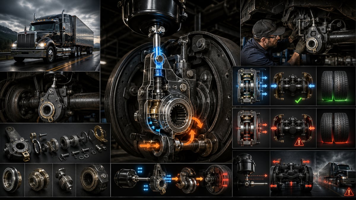
When a tractor unit rolls onto the inspection pit, the driver's only complaint is often the same: "The brakes still hold, but not like they used to — I'm pushing the pedal further down." Before anyone pulls a drum, a simple chalk mark on each push rod tells the real story: measured with the brakes fully applied, the travel on one side of the rear axle is nearly double the other. The linings aren't worn out, the brake chamber is sound, and system pressure is where it should be. What has failed is the mechanism that is supposed to close, on its own, the gap that opens as the lining wears. This guide treats the slack adjuster not as an isolated spare part, but as the centre of the adjustment chain that converts the chamber's push force into torque at the camshaft and keeps brake stroke correct for the working life of the vehicle.
Where Does Force Turn Into Torque in an Air Brake System?
In an air brake system, the pedal is not a force-generating component — it is a control device. Pressing it does one thing only: it sends a metered pressure signal down the brake circuit. Turning that pressure into work at the wheel happens in two stages: pressure is first converted into linear push force across a diaphragm area, and that force is then converted, over the length of an arm, into torque that rotates the camshaft. The first stage belongs to the brake chamber; the second belongs to the slack adjuster.
The chamber multiplies incoming pressure by its effective diaphragm area and delivers the result to the push rod. The push rod does not connect to the brake shoes directly — it connects to the slack adjuster. One end of the arm is joined to the push rod by a clevis and pin; the other end is splined onto the camshaft. As the push rod advances, the arm rotates the camshaft about its own axis, and the S-cam at the shaft's end spreads the two shoes apart and presses the linings onto the drum. Three factors together set the braking force at that wheel: the chamber's effective area, line pressure, and the length of the slack adjuster's lever arm.
How much that arm length matters is easy to underestimate. With the same chamber and the same pressure, changing only the arm length changes torque at the camshaft in direct proportion — fit arms of different lengths on the two sides of one axle and that axle is unbalanced from the start. The chamber's own failure patterns, diaphragm fatigue and replacement discipline are a separate subject, covered in our brake chamber guide; here the chamber is simply the force source feeding the slack adjuster. The arm's second job — and the less obvious one — is not transmitting force but preserving this geometry as the lining wears.
What Changes as the Lining Wears? Clearance, Stroke and Brake Force
When new linings are fitted, a small running clearance is left between the lining surface and the inside of the drum. This clearance is not arbitrary: it lets the lining pull fully away from the drum when the brake is released, so the wheel turns freely. Close the clearance to zero and the lining drags constantly, heating the drum and wearing both parts out quickly; leave it too large and the brake engages late, lengthening stopping distance.
As the lining wears thinner, the clearance grows on its own. Producing the same braking effect then requires the camshaft to rotate a little further each time, which means the push rod has to travel a little further too. The distance the push rod covers when the brake is applied is called stroke, and stroke is the direct, drum-off indicator of lining wear.
If stroke were only a wear gauge, the issue would stay minor. The real problem is that the chamber's output force is not constant across its stroke. In a diaphragm chamber, as the push rod advances the diaphragm flexes further, the effective area shrinks, and the push force produced at the same pressure drops. In other words, a lengthened stroke doesn't just mean the brake engages later — it means the same line pressure produces less braking force. At first the driver compensates by pressing the pedal a little further; in an emergency stop, there is no more pedal left to give. That is why the stroke limit is not a maintenance courtesy but a safety threshold: exceeding it proves that wheel's share of braking capacity is below what was calculated, and the shortfall is carried by the other wheels.
Manual vs. Automatic Brake Slack Adjuster: What Is the Difference?
Closing the clearance created by wear has been solved two different ways. In a manual slack adjuster, a worm gear inside the housing is turned by an adjusting screw; a technician turns that screw at set intervals on every wheel, tightening the clearance and bringing stroke back into range. The operation itself is simple, but it depends entirely on people: brake balance is only ever as good as who adjusted which wheel, when, and by how much.
In an automatic slack adjuster, the same worm gear is turned not by a technician's hand but by the brake's own motion. The arm measures how far it rotates on every application; once rotation exceeds a reference angle built into the design, the excess is fed through a one-way clutch to the worm gear and the clearance is closed by one small increment. Adjustment doesn't happen in one move — it happens step by step, over hundreds of brake applications — which is why, on a properly working arm, stroke stays inside a narrow band for the entire life of the lining.
The move to automatic adjusters was never really about saving labour — it was about repeatability. Manual adjustment requires that four, six or ten wheels all be handled by the same hand with the same discipline, and in the field that rarely happens. Skip or over-tighten one wheel's adjustment and axle balance goes off, wear piles up on one side, and kilometres later it shows up as pulling, one-sided heat and premature lining failure. The automatic slack adjuster removes that human variable from the system, and it has been standard equipment on new air-braked vehicles for a long time.
| Comparison point | Manual slack adjuster | Automatic slack adjuster |
|---|---|---|
| Clearance take-up | Done by hand by a technician at set intervals | Done incrementally, on its own, at every brake application |
| Maintenance load | Periodic adjustment required on every wheel | Verification, not adjustment: stroke is measured and logged |
| Risk of incorrect setting | Over- or under-adjustment is common | Internal clutch protects against overload |
| Typical fault symptom | Stroke slowly grows because adjustment was skipped | Stroke grows even though nothing was skipped, and returns even after a manual fix |
| Service approach | Adjusting screw is turned on a schedule | Manual adjustment is done only at installation and lining replacement |
| What the measurement means | Whether adjustment time has arrived | Whether the mechanism itself is working |
The table's last row is the critical one. On a manual system, a long stroke simply means "it's time to adjust"; on an automatic system, a long stroke is itself a fault report, because on a healthy arm stroke should never have grown in the first place. Missing that distinction is the single most common mistake in the field.
How Does an Automatic Slack Adjuster Work? Overtravel Detection and Incremental Take-Up
Inside the arm housing sits a gear that engages the camshaft, and a worm gear capable of turning it. In normal operation the arm rotates the camshaft as a single unit and the worm gear stays still. For adjustment to kick in, the angle the arm rotates through has to exceed a reference angle defined in the design.
That reference angle is generated one of two ways. In one common family, a short control arm on the adjuster is anchored to the axle or chamber bracket; when the brake is applied the slack adjuster rotates while the control arm stays fixed to that anchor point, and the resulting relative angle is the measure of how far the clearance has opened. In the other family, the reference is generated by a spring-loaded control mechanism inside the housing itself and needs no external linkage. Either way, the logic is the same: the arm compares "the rotation it should make" against "the rotation it actually made."
As long as that difference stays under the threshold, no adjustment happens — the clearance is already correct. Once the threshold is exceeded, the one-way clutch feeds the excess to the worm gear, which advances the camshaft toward the lining by a very small angle. The distance covered in a single application is invisible to the eye, but a truck brakes thousands of times a day, and the take-up accumulates over those repetitions. The design's goal isn't fast adjustment — it's keeping clearance inside a narrow band, continuously.
In most designs, completing the adjustment while the brake is released, rather than while it's applied, is a deliberate choice: taking a reference from a hot, expanded drum under load could leave the lining dragging once it cools. For the same reason there's an internal slip clutch: if the adjusting gear is overloaded, the clutch slips and lets the motion through without damaging the internal parts.
It's worth remembering that the arm doesn't reason about causes — it only reacts to the angle difference it sees: worn lining and a loose bushing or a worn clevis pin register as exactly the same "extra rotation" to it. That's why stroke should never be judged on its own, but always read together with camshaft freeplay and lining thickness.
What Specifications Determine the Right Brake Slack Adjuster?
Choosing the correct brake slack adjuster is not a matter of reading a part number off a catalogue — several dimensions have to match at once. A wrong arm can still bolt on, appear to work, and even show a plausible stroke reading, yet quietly unbalance the axle because the torque or the swing angle it actually produces differs from what was intended. The dimensions that matter are:
- Spline size: The diameter and tooth count of the internal spline that seats on the camshaft. The real risk is forcing on an arm whose spline is close but not exact.
- Lever arm length: The distance between the camshaft centreline and the push-rod clevis pin; it sets braking force directly and must be identical on both sides of the axle.
- Arm type and control mechanism: Whether it uses a control arm linkage or an internal reference, and whether the control arm's mounting point matches the axle hardware.
- Handing: Housing shape correct for the left or right wheel. In most designs, both the adjusting gear's direction and the arm's bend follow which side it's on.
- Working angle range: The angle window the arm must stay within between released and fully applied — it has to suit the chassis, suspension and chamber layout.
The most common field mistake is replacing the arm on the faulty side while leaving the other side untouched. When the two arms are from different production runs or different lengths, the axle will not produce equal braking force even if both measured strokes fall within limits. The rule of thumb: treat the slack adjuster as an axle-level, pairs component.
How Is Brake Stroke Measured? Point, Reference and Conditions
Stroke measurement is the most informative, least equipment-hungry check in air brake maintenance — all it takes is a marker, a rule and the right conditions. Reliability depends far more on getting the conditions right than on the tool used. A reading taken under the wrong conditions is worse than no reading at all: it manufactures false confidence.
- Park the vehicle on firm, level ground, shut off the engine, and chock the wheels in both directions — the parking brake will be released, so chocks are non-negotiable.
- Build the air system up to full pressure. Take the reading with the system near cut-out pressure; a reading taken at low pressure will not reflect the true condition.
- Make sure the brakes are cold. After a long descent the drum has expanded, which makes measured stroke read shorter than it is and can mask a fault.
- Release the spring brake chambers on the parking axles. The measurement is taken with the service brake only — the movement produced by spring force is not a comparable value.
- With the brake released, put a single, thin reference mark on the push rod near the point where it exits the chamber body; a thick mark introduces reading error.
- Apply the service brake fully, and hold the application steady for the duration of the reading; the application must not drop system pressure noticeably.
- Find the mark's new position relative to the chamber body and measure the distance between the two positions. That value is the applied service stroke for that wheel.
- Repeat the same procedure on every wheel and record the values with axle and side identified — measuring a single wheel hides any imbalance.
- Compare the values against the adjustment and limit figures defined in the OE manual for the chamber type fitted to that vehicle. The limit depends on chamber type — a single number does not apply across all vehicles.
In the field, a shortcut is sometimes used where the push rod is pried out with a bar without applying the brake. That method gives a sense of free play but does not deliver applied stroke, and the force used to pry varies from person to person, so it is not repeatable. Whenever the measurement is going to drive a decision, always use the full-application method.
What Does the Measured Stroke Tell You? Condition, Meaning and Action
A stroke value on its own isn't a number — it's a statement. Two identical-looking values can mean very different things depending on the previous reading and on the opposite wheel.
| Measured stroke condition | What it signals | Action required |
|---|---|---|
| Unusually short, almost no travel | Lining is dragging constantly, or the arm has been over-adjusted | Check free wheel rotation and drum temperature, back off the over-adjustment |
| Within range and close between both sides of the axle | Clearance is being taken up correctly, mechanism is working | Log the value as the reference for the next check |
| Within limit but grown noticeably since the last reading | Take-up is still working, but lining may be approaching its wear limit | Measure lining thickness, shorten the check interval |
| At the re-adjustment limit | A fault has started at the arm, camshaft, or lining | Before touching the arm, verify camshaft freeplay, clevis clearance and lining condition |
| Above the limit | Braking force at that wheel is reduced; the vehicle is technically defective | Find and fix the root cause before the vehicle is dispatched; adjustment alone is not sufficient |
| Clear difference between right and left on the same axle | Unbalanced braking, pulling and one-sided wear risk | Treat the longer side as the target; compare chamber type, arm length and air delivery |
| Grows back again soon after a manual adjustment | The automatic mechanism is not taking up clearance, the fault is persistent | Do not re-adjust; remove and inspect the arm, camshaft and bushings |
The common lesson across every row: a measurement is not a verdict, it's a question. A stroke over the limit doesn't say "adjust it" — it says "something here isn't taking up clearance, find out why." Any adjustment made before the cause is found only postpones the fault to the next check.
Standards and further reading
This subject is governed by the equipment rules for air-braked commercial vehicles. In the United States the federal air brake standard, FMVSS 121 (49 CFR 571.121) defines the reservoirs, protection and timing a compliant system must provide, and Europe applies the equivalent limits of UNECE Regulation No. 13. For further detail, see the illustrated reference guide at airbrakecompressor.com. Always confirm specific figures against the current regulation and the vehicle manufacturer service data.
Outside the United States the equivalent duties sit in national law. In the United Kingdom, regulation 18 of the Road Vehicles (Construction and Use) Regulations 1986 requires every part of the braking system to be maintained in good working order. In Canada, air brake systems fall under the Motor Vehicle Safety Regulations, which contain CMVSS 121.
Is a Long Stroke Always a Slack Adjuster Fault?
No. Long stroke is the shared symptom of a fault anywhere in the adjustment chain, and the slack adjuster is only one link in it. Replacing the arm outright usually suppresses the symptom for a while; if the real cause is left in place, the new arm reaches the limit just as fast.
| Possible cause | Distinguishing symptom | How to confirm |
|---|---|---|
| Internal mechanism of the automatic slack adjuster isn't working | Stroke grows back quickly after a manual adjustment | Watch for incremental movement at the adjusting gear as the brake is applied and released |
| Control arm linkage has loosened or broken | Automatic adjustment never engages, the arm swings free | Check the control arm's connection to its fixed anchor and the anchor's condition |
| Chamber push force has weakened; diaphragm is fatigued or leaking | Air leak noise around the chamber under pressure, delayed response | Soap-and-water leak test, inspect chamber body and fittings |
| Camshaft is seized or its bushing is dry | Slow return after the brake is released, drum runs hot | Turn the camshaft by hand to check freeplay and radial/axial play |
| Lining thickness has reached the wear limit | Adjustment corrects stroke, but it returns to the limit quickly again | Measure lining thickness, assess rivet or backing depth |
| Drum is worn, bore enlarged or out of round | Stroke stays high even with new lining, brake pulsates | Measure drum bore at several points and compare against the wear limit |
| Slack adjuster is the wrong length or mounted at the wrong angle | Arm angle visibly differs side-to-side on the same axle | Compare arm type, length and mounting angle against OE data |
| Push-rod clevis, pin or bushing is worn | Dead play, a clunk at the start of braking, unstable readings | Check clevis and pin play by hand with the brake released |
Rows four and five deserve special attention, because both wrongly get the automatic slack adjuster blamed. If the camshaft is seized, clearance will not close even with a perfectly good arm; if the lining is worn out, the arm has already done everything it can and simply has no adjustment left to give. How lining thickness affects stroke, its wear symptoms and replacement timing are covered in detail in our brake lining replacement guide — when stroke approaches the limit, that's usually the first place to look.
Why Manually Winding Back an Automatic Slack Adjuster Is Not a Fix
When a vehicle due for inspection or a dispatch deadline shows stroke over the limit, the first instinct is to turn the adjusting screw and shorten it. It takes a few minutes, the reading corrects immediately, and the vehicle goes out. This is the most common — and most misleading — intervention performed on automatic slack adjusters.
The first problem is a lost diagnosis. On an automatic system, long stroke doesn't mean clearance has grown — it means the mechanism that is supposed to close the clearance isn't working. A manual adjustment silences the warning without removing the cause; the lining keeps wearing on the road, take-up still doesn't happen, and stroke returns to the same point soon after. The only difference is that this time, nobody is watching for it.
The second problem is mechanical. The adjusting screw on an automatic arm isn't designed for periodic use — it's there to set the initial clearance at installation and to reset the arm at lining replacement. Repeatedly forcing it manually fatigues the internal clutch, the worm gear and the gear wheel. Force the slip clutch enough times and its holding torque drops, until the mechanism can no longer produce enough force at the moment it actually needs to adjust — in other words, the habit of manual adjustment ends up causing the very fault it was meant to hide.
The third problem is safety. Because the goal is to shorten the stroke, the intervention is often taken further than it should be. With clearance over-tightened, the lining never fully clears the drum; the vehicle drags a light brake constantly at cruising speed. The result is a hot drum, a lining that wears out fast, reduced brake effectiveness on long descents, and heat cycling that can start cracks in the drum.
Camshaft and Bushing Clearance: Their Effect on Adjustment
The camshaft that the slack adjuster transmits torque to is supported at two points by bushings and contacts the linings through the cam profile at one end. Play at these support points is the quietest variable in the adjustment chain, because it never announces itself directly — it shows up by throwing off every other measurement instead.
When a bushing wears, the camshaft can't stay centred. When the brake is applied, the shaft shifts sideways by the amount of that play before it starts to rotate, and that lost motion never reaches the cam profile — part of the travel is simply wasted. The slack adjuster reads this as "clearance has grown" and tries to compensate. Even with plenty of lining thickness left, the mechanism keeps adjusting, the lining ends up sitting closer to the drum than it should, and dragging begins. In other words, a worn bushing can mislead a perfectly good automatic arm into over-adjusting.
The opposite case is more common. A bushing that has gone too long without grease, or that has let in water and road grit, seizes up. In that state, the camshaft can't spring freely back when the brake is released; the lining never fully clears the drum, and on the next application the mechanism can't find a correct reference. On a seized camshaft, stroke will not correct no matter how sound the slack adjuster is, and pulling the arm for inspection turns up nothing wrong with it. This is the most common cause behind the complaint "we fitted a new arm and nothing changed."
The check is simple and needs no drum removal. With the brake fully released, gently work the slack adjuster by hand in both directions; a perceptible bit of give confirms the camshaft can rotate. Radial play is felt by holding the arm housing still and pressing lightly on the shaft, perpendicular to its axis. Excessive play, a dry grinding feel, or no movement at all point to the camshaft side of the problem — check the bushing, seal and grease condition.
Slack Adjuster Installation: Mounting Angle, Marking and Initial Setup
Installing a slack adjuster isn't difficult, but it is a geometry-sensitive job. An arm mounted at the wrong angle looks fine on the day it's fitted; the problem only surfaces once the lining has worn enough to push the arm's working angle outside its window.
- Secure the vehicle, chock the wheels, bleed system pressure per the manufacturer's procedure, and mechanically cage the spring parking chamber with its locking bolt.
- Before removing the old arm, mark its position on the camshaft end and the control arm's anchor point; these marks become the starting reference for the new installation.
- Clean dirt, rust and old grease from the camshaft end, the splines and the mating surfaces; forcing on an arm over debris permanently damages the splines.
- Confirm the camshaft turns freely in its bushings. Fitting a new arm onto a seized shaft only transfers the fault onto the new part.
- Seat the new arm on the camshaft, set its axial position, and fit the retaining hardware in the manufacturer's specified order; the arm must not be left with axial play on the shaft.
- Check the angle between the push rod and the arm. Common practice is for the push rod to sit close to a right angle to the arm at full application — the geometry that transmits force most efficiently and loses the least over the stroke.
- On control-arm-linked types, connect the control arm to the manufacturer's specified fixed point in the position shown. A control arm anchored to the wrong point will either never activate the mechanism or force it to adjust continuously.
- Set the initial clearance per the manufacturer's procedure: the adjusting screw is generally tightened until the lining contacts the drum, then backed off a specified amount to leave the running clearance.
- Put a permanent stroke reference mark on the push rod. Reading from the same reference point at every future check is what makes measurements comparable over time.
- Pressurise the system, apply and release the service brake fully a few times to let the mechanism settle, then measure stroke and compare both sides of the axle.
The step most often skipped during installation is the permanent stroke mark on the push rod. That small detail is what speeds up every later check and removes the variation between different people's readings — it's the one thing that keeps stroke records comparable across an entire fleet.
What Does Uneven Stroke Side-to-Side on the Same Axle Mean?
Both wheels can measure within limit individually and the vehicle can still brake unevenly. What matters isn't the absolute values but the gap between them. A noticeable difference between the right and left side of the same axle means the two sides are braking at different times and with different force.
The consequences don't show up in just one symptom. Under hard braking, the vehicle pulls toward the side with the shorter stroke; on wet roads, the shorter-stroke side tends to lock up earlier. Over the long term, wear becomes uneven too: the side that engages early burns through both lining and drum faster, while the side that engages late may glaze from never heating up properly. In trailer groups, the same imbalance can extend all the way to uneven tyre wear.
The order of investigation is set. Mechanical checks come first: are both arms the same type and length, are the chamber types matched, do both camshafts have equal freeplay, are both linings the same thickness. If all of that checks out, attention moves to the air side — the length, bore and valve placement of the lines feeding the chambers can all affect response time. Sometimes the symptom isn't limited to a single wheel but spans a whole axle or trailer group, in which case the search shifts to air distribution. For symptom-cause-solution pairings across the whole system, our air brake fault diagnosis guide offers a step-by-step check sequence.
Periodic Stroke Checks and Fleet Record Discipline
An automatic slack adjuster isn't a maintenance-free part — it's a part that requires no adjustment. That distinction is the foundation of any fleet maintenance programme: on a vehicle fitted with automatic arms, the recurring task is not turning an adjusting screw on a schedule, but periodically verifying that the mechanism is actually doing its job.
- Set the check interval. Shorten it for urban delivery, construction site work, routes with long descents, and trailer operation — apply whichever comes first, distance or time.
- Always measure under the same conditions: system fully pressurised, brakes cold, parking brake released, vehicle on level ground, wheels chocked.
- Read from the permanent mark on the push rod at each wheel and log the value together with axle and side.
- Compare both sides of the same axle side by side; evaluate the difference before the absolute value.
- Compare each reading against the OE adjustment and limit values for the chamber type on that vehicle; don't apply one limit across different chamber types.
- Compare against the previous reading and work out the rate of change. A stroke that's still within limit but climbing fast is more urgent than one sitting at the limit but holding steady.
- On wheels over the limit, start a root-cause investigation before adjusting; log the finding and the action taken alongside the reading.
- Whenever a slack adjuster, chamber, lining or camshaft is replaced, log the part type and position — without that information, later readings can't be compared meaningfully.
- Track recurring positions across the fleet. Vehicles that consistently show long stroke on the same side of the same axle may be pointing to a systematic setup or route effect rather than a one-off fault.
Technical Reference Values, General Benchmarks and the Correct Diagnostic Order
The table below gathers the figures most often needed in the field for slack adjuster and stroke work, at the level of a benchmark. The information here isn't meant to drive a decision — it's meant to help judge whether a result you've measured is plausible.
| Quantity or topic | General reference benchmark | Interpretation |
|---|---|---|
| Chamber nominal stroke | Defined on the chamber type plate and in OE documentation | Limit values are set relative to this nominal figure and vary by type |
| Re-adjustment limit and maximum limit | Two separate thresholds are defined for the same chamber | The first marks when to intervene, the second marks an unacceptable condition |
| Angle between push rod and arm | Should be close to a right angle at full application | A deviated angle produces less torque at the same pressure |
| Arm length per axle | Must be identical on both sides | A length mismatch unbalances braking even if readings look normal |
| Camshaft freeplay and bushing clearance | Within OE tolerance, free and grind-free rotation | Seizure blocks adjustment, excess play drives the mechanism to over-adjust |
| Use of manual adjustment | Installation and lining replacement only | Routine manual adjustment hides faults and fatigues the mechanism |
| Scope of slack adjuster replacement | Assessed at axle level, in pairs | Replacing only one side can unbalance the axle |
The real rule behind this table is that no numerical benchmark for a slack adjuster can be used independently of the chamber type and axle equipment on the vehicle in front of you. Even two tractors from the same manufacturer can call for very different limits because of a different chamber size or different brake hardware.
As a closing note, it's worth keeping the diagnostic order in mind. The slack adjuster sits between the chamber and the lining, and it inherits the health of both. When faced with a long stroke, the sequence runs like this: first confirm the measurement was taken under correct conditions, then that the chamber is producing force, then that the camshaft turns freely, then that the lining and drum still have adjustment margin left — the slack adjuster itself is questioned last. Follow that order and fewer parts get replaced, faults recur less, and — most importantly — the vehicle's braking capacity comes back in reality, not just on paper. In every case, the current OE service documentation for the vehicle's chassis and axle code is authoritative.
It helps to know the unit that produces the thrust at the start of this chain; for its design and failure symptoms, see our article what is a brake chamber.
Pushrod stroke is also a key item in DOT roadside inspections; our DOT air brake inspection checklist shows how inspectors measure it and what else they check.
Shop this part: Actuating Lever
Tags
Frequently Asked Questions
- What does a brake slack adjuster do?
- A brake slack adjuster converts the brake chamber's linear push force, over the length of its arm, into torque that rotates the camshaft; the camshaft then presses the linings onto the drum. Its second, less obvious job is adjustment: it takes up the running clearance that grows as the lining wears, keeping brake stroke inside a narrow band. Because of this, the arm's length and mounting angle directly determine how much braking force that wheel produces.
- How does an automatic slack adjuster work?
- Inside the arm housing is a gear engaged with the camshaft and a worm gear that can turn it. On every brake application, the angle the arm rotates through is compared against a reference angle built into the design; if rotation exceeds that angle, the excess is fed through a one-way clutch to the worm gear and the clearance is closed by one small increment. Adjustment happens step by step over hundreds of applications, not in a single move. An internal slip clutch prevents the mechanism from being overloaded.
- How do you measure brake stroke?
- The vehicle must be on level ground, wheels chocked, system fully pressurised, brakes cold and the parking brake released. With the brake released, put a thin reference mark on the push rod near where it exits the chamber body. Then apply the service brake fully and measure how far the mark moved — that distance is the applied service stroke for that wheel. Repeat on every wheel and record the values with axle and side.
- What should the brake stroke limit be?
- There is no single figure that applies to every vehicle. The limit is defined against the nominal stroke of the chamber fitted at that wheel and varies by chamber type; most applications also define two separate thresholds — a re-adjustment limit that signals when to intervene, and a maximum limit that marks an unacceptable condition. Valid figures must come from the current OE service manual for the vehicle's chassis and axle code.
- What does long brake stroke mean?
- Long stroke is the shared symptom of a fault anywhere in the adjustment chain, and the slack adjuster is only one possible cause. The most common culprits are an automatic slack adjuster whose internal mechanism has stopped working, a loosened control arm linkage, weakened chamber push force, a seized camshaft or dry bushing, lining worn down to its limit, or an oversized drum bore. That's why the chamber, camshaft and lining should all be confirmed sound before the arm itself is replaced.
- Does a longer stroke really reduce braking force?
- Yes. In a diaphragm chamber, as the push rod advances further the diaphragm flexes more, its effective area shrinks, and the push force produced at the same pressure drops. So a long stroke doesn't just mean the brake engages later — it means the same pedal pressure delivers less braking force. A driver can compensate for a while by pressing the pedal further, but there's no margin left for that in an emergency stop.
- Is it okay to manually adjust an automatic slack adjuster?
- Not as a fix. On an automatic system, long stroke means the mechanism that should be closing the clearance isn't working; a manual adjustment silences that warning without removing the cause, and stroke returns to the same point soon after. Repeatedly forcing the adjusting screw also fatigues the internal clutch and gearing. Manual adjustment should only be used at installation and at lining replacement, following the manufacturer's procedure.
- What's the difference between a manual and an automatic slack adjuster?
- On a manual arm, a technician closes the clearance by turning the adjusting screw at set intervals; on an automatic arm, the brake's own motion does the same job through an internal clutch and worm gear. The difference is more than labour: on a manual system, long stroke simply means it's time to adjust, but on an automatic system a long stroke is itself a fault report, because on a healthy arm stroke should never have grown in the first place.
- Does camshaft bushing play affect the slack adjuster?
- Directly. A worn bushing lets the camshaft shift sideways before it starts to rotate, so part of the motion never reaches the cam; the slack adjuster reads this as extra clearance and can over-adjust as a result. A seized, dry bushing has the opposite effect — the camshaft can't spring back freely when the brake releases, the mechanism can't find a correct reference, and stroke won't correct no matter how good the arm is. This is the most common reason a newly fitted arm doesn't solve the problem.
- What does a stroke difference between the right and left side of an axle mean?
- Even if both readings fall within limit, a clear gap between them means the two sides are braking at different times and with different force. Under hard braking the vehicle pulls toward the shorter-stroke side, and wear becomes uneven over time. The check starts on the mechanical side — arm type and length, chamber type, camshaft freeplay and lining thickness on both sides — before moving to air line length, bore and valve placement if everything mechanical checks out.
Related Articles

Air Dryer: Faults, Replacement & Maintenance Guide
How a truck air dryer's charge and purge cycle keeps moisture and oil out of the brake system, and what a hissing purge valve or water in the tanks means.
Brake Chamber: Faults, Replacement & Maintenance Guide
Service and spring brake chambers on trucks and trailers: diaphragm-leak and stroke diagnosis, why caging is mandatory before removal, and safe replacement.
How to Read an Air Brake Diagram: Circuit Guide
How do you read an air brake system diagram? Symbol language, line colours, port codes, circuit split, trailer lines and fault-tracing, step by step.


