Brake Chamber Types and Sizes: Choosing T, DD and Spring Chambers
What do T24, T30 and 24/30 mean? A guide to brake chamber types, effective area, stroke, flange size and correct selection for heavy trucks.
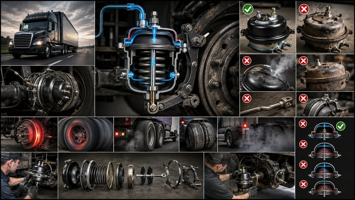
A brake chamber on a trailer axle needs replacing. Over the phone it's called "a 24-type chamber," the part that arrives bolts up, the stud spacing lines up, the air fitting matches. Once the vehicle is back on the road, though, that axle grips later than its neighbor, and after a few thousand kilometers the linings on that side are noticeably more worn. The part isn't defective, and it wasn't installed wrong; it's just that the second half of the marking on the housing, the push rod length, or the usable stroke is different from what was actually needed. In a heavy commercial vehicle, the real question in chamber selection is usually not "which part failed" but "which part should have been fitted." This guide treats the chamber from the type-and-size side rather than the failure side: what the markings say, effective area and stroke, tractor-versus-trailer differences, and what to measure before ordering.
Where Pressure Becomes Force: What Does a Brake Chamber Do?
A brake chamber is the mechanical converter in the air brake system that turns stored compressed air into linear push force. The pedal command reaches the chamber as pressure through a series of valves; the chamber gathers that pressure over a diaphragm and drives the push rod outward. In an S-cam drum system this push goes to the slack adjuster and then the camshaft; in a disc system it acts directly on the caliper. Braking force is directly proportional to the push the chamber generates.
The rest of the system carries a signal; the chamber does the work. A misbehaving valve delivers pressure late or short; a wrong-type chamber delivers the wrong force or leverage even when pressure is exactly right. The chamber is the on-vehicle expression of the brake calculation: the axle maker sizes brake torque to a specific drum diameter, slack adjuster length and chamber size, and changing any one of the three changes the calculation with it.
Two quantities decide the force a chamber produces: the diaphragm's effective area and the pressure acting on it. A third quantity, usable stroke, tells you over how much travel that force can be sustained. Type selection revolves around these three ideas, and the handful of digits stamped on the housing are really shorthand for them.
Three Members of the Chamber Family: Service, Spring and Combination Types
In heavy commercial vehicles, chambers split into three main groups by the job they do, and the groups are not interchangeable. The split comes from how each one applies the brake: one pushes with air, another pushes with a spring once the air is gone, and the third combines both in a single housing.
The service chamber (single-diaphragm type) applies only the service brake. When the pedal is pressed, air enters and the diaphragm pushes the rod out; when the pedal is released, air exhausts and the return spring pulls the rod back in. It carries no parking spring, so once the vehicle is stationary it produces no holding force at all. On heavy vehicles it's typically used on the steer axle and on some trailer axles.
The spring chamber (parking section) works the opposite way. Its heavy compression spring stays held back for as long as pressurized air is supplied, and the brake remains released. Once the air is exhausted, the spring is freed and mechanically applies the brake. This design provides the parking brake, and it doubles as a safety function, because the brake engages on its own whenever the system suffers a serious pressure loss.
The combination chamber (dual-section type) puts a service section and a spring section in one housing. The front section applies the service brake, the rear section produces the parking and emergency brake. The two sections drive the same slack adjuster through a shared push rod. This is the standard fit on drive axles and on most trailer axles.
| Type | Where it's used | Typical application | What to watch |
|---|---|---|---|
| Service chamber (single-diaphragm) | Steer axle, some trailer axles, some mid-axles | Service brake only; no parking function | If swapping to a combination unit, check the axle bracket, weight and clearance |
| Spring chamber (separate parking section) | Axles carrying a parking brake, some older applications | Parking and emergency brake, applied by spring once air is exhausted | The spring must be released mechanically before removal |
| Combination chamber (service + spring) | Drive axle, trailer axles, most modern applications | Service and parking brake in one housing | The two sections are sized separately; both need to be verified |
| Disc brake chamber (bolts directly to the caliper) | Air disc brake axles | Type that pushes the caliper mechanism directly | Mounting interface is not the same as the drum type; don't mix them up |
| Long-stroke type (service or combination) | Applications with high stroke demand | Same area, longer usable travel | Don't confuse with the standard type; adjustment and inspection limits differ |
The last two rows in the table are where the field gets confused most often: a long-stroke unit can share the exact same housing size as the standard type, and telling the two apart by eye isn't always possible.
T24, T30, 24/30: What Do the Numbers on the Designation Mean?
The designation stamped or labeled on a chamber's housing is the part's identity, not a random catalogue number. In common trade usage, a single number denotes a service chamber, and two numbers separated by a slash denote a combination chamber.
In "T24" or simply "24," the number tells you the chamber's effective area in roughly square inches. This is a naming convention that took hold in the industry; even though everything around it is metric, the designation itself has been kept in square inches internationally. So a T24 has roughly 24 square inches of diaphragm area, a T30 roughly 30. The bigger the number, the bigger the push force produced at the same pressure.
Double designations such as 24/24, 24/30 or 30/30 denote combination chambers; in some sources they're also called DD, short for double diaphragm. The first number describes the service (foot brake) section, the second describes the spring (parking) section. This distinction matters, because "I need a 30" isn't enough information on a combination unit by itself — it leaves open which of the two sections is meant.
Some manufacturers tack a letter onto the designation; an "L," "LS," or similar suffix generally points to a long-stroke type. European-origin documentation also uses terms like "diaphragm brake cylinder," "spring brake cylinder" and "combination cylinder" for the same three families. OE sources such as Knorr-Bremse, Wabco, Bendix, Haldex and Meritor each run their own type coding, and those codes are read off the vehicle's original equipment list.
Effective Area: The Physics Behind the Number
The force a chamber produces comes down to a simple product: force equals effective area times pressure. The larger the diaphragm surface exposed to air, the larger the force delivered to the push rod at the same pressure. The number in the designation describes exactly this area, and that's where the quantitative side of type selection comes from.
Effective area isn't fixed, though. As the diaphragm advances with the push rod, it rolls under at the edges and the true pressure-exposed surface shrinks. The result: the closer a chamber gets to the end of its stroke, the less force it produces at the same pressure. As the lining wears, stroke lengthens; as stroke lengthens, force drops — this is the mechanism behind the quiet decline in brake performance that comes with wear. The slack adjuster is the part meant to compensate for it.
| Designation | Approximate effective area | Order-of-magnitude force at mid-stroke | Typical field of use |
|---|---|---|---|
| T12 | Roughly 12 square inches | On the order of 6 kN | Light axles, small trailer applications |
| T16 | Roughly 16 square inches | On the order of 8 kN | Mid load class, some steer-axle applications |
| T20 | Roughly 20 square inches | On the order of 10 kN | Steer axle and medium-duty drum axles |
| T24 | Roughly 24 square inches | On the order of 12 kN | The most common size; steer axle and many trailer axles |
| T30 | Roughly 30 square inches | On the order of 15 kN | Heavily loaded axles, drive-axle service sections |
| T36 | Roughly 36 square inches | On the order of 18 kN | High-load and special-body applications |
The force figures in the table are order-of-magnitude results from multiplying area by a typical working pressure; they aren't catalogue data from any manufacturer, and friction, return-spring load and stroke loss aren't accounted for. The only document that fixes the correct force for a given axle is the axle manufacturer's brake calculation together with the vehicle's OE service documentation.
The practical rule that follows from this is straightforward: a bigger number isn't always better. Fitting a chamber larger than what the calculation calls for makes that axle grip earlier and harder than the others. That throws off the load distribution across a vehicle that would otherwise be balanced, and it burns through one axle's linings quickly. The point of the brake calculation isn't to reach the highest possible force — it's to keep the distribution across axles correct.
Stroke Length and the Long-Stroke Chamber Concept
Stroke is the distance the push rod travels forward from its rest position. The travel the chamber uses up before the lining reaches the drum or the disc is the stroke it consumes. This distance is short with a new lining and grows longer as the lining wears. The slack adjuster automatically takes up that growth to keep stroke within a set range.
Every chamber has a rated stroke and a maximum usable stroke. Rated stroke is the working range in which the chamber can deliver its designed force; maximum stroke is the physical limit the diaphragm can travel to. The zone between the two is the safety margin: force keeps being produced, but it keeps weakening. If stroke is continually pushed into that zone, the brake can look like it's working while it isn't delivering the torque it should.
A long-stroke chamber is a type built to offer a longer usable travel at the same effective area. Its housing size and designation can be identical to the standard type; the difference is in diaphragm geometry and internal clearance. The point is to keep force sustained over a wider range on axles where lining wear or the nature of the application drives up stroke demand.
| Criterion | Standard-stroke type | Long-stroke type |
|---|---|---|
| Order of usable travel | Roughly in the 55-65 mm range | Can reach roughly 70-80 mm |
| Effective area | As given by the designation | Similar area at the same designation |
| Range over which force holds up | Narrower; a sharp drop near the end of stroke | Wider; more wear margin |
| How it's identified | No added letter, plain type code | Added letter in the type code; on some makers a square identification hole or a separate label |
| Adjustment and inspection limit | The stroke limit that belongs to the standard type | Its own, separate stroke limit |
| Risk if mixed up | Fitted where a long-stroke unit is needed, travel falls short | Fitted where a standard unit is needed, the stroke limit gets read wrong |
The last row of the table is the critical one. When the two types end up mixed on the same axle, a single stroke limit can't be used to interpret both measurements: a reading that would be perfectly acceptable on a standard chamber can mean an early warning on a long-stroke one. That's why the two sides of the same axle should never carry different types.
How the Two Sections of a Combination Chamber Work Together
A combination chamber has two separate air lines, each feeding a different section. The service line carries the pedal command and reaches the front section; pressure in this line changes with pedal position. The park line feeds the spring section and, in normal driving, stays under continuous pressure. Pressure in the spring section keeps the spring compressed, which means the brake stays released.
When the parking brake is applied, or when system pressure drops below a critical level, the park line exhausts, the spring is freed, and it drives the push rod outward. Because the same rod is also driven by the service section, the two forces act on the same slack adjuster. This design has an important consequence: pressing the service brake while the parking brake is already applied can let the two forces add together. Modern systems include valves to prevent that, but if the system has been tampered with or a valve has failed, the risk of mechanical overload is real.
A third distinction on the combination type is whether the spring section is repairable or a sealed unit. In some designs the service diaphragm can be renewed on its own, while the spring section, for safety reasons, is usually treated as a sealed unit and replaced whole. For full removal, replacement and maintenance procedures, see the brake chamber fault diagnosis, replacement and maintenance guide; this article stays focused on selection and sizing.
Mounting Flange, Stud Spacing and the Installation Interface
Getting the right designation is only half the job. For the chamber to actually seat on the axle, the mounting interface has to match too, and that interface is made up of several separate dimensions. The most common disappointment in the field is a chamber of the correct type whose flange won't seat on the axle bracket.
The first part of the interface is the stud pattern: the chamber bolts to the axle bracket through two studs projecting from the back of the housing, and the center-to-center spacing of those studs varies by type family. Two chambers carrying the same designation can still be built with different stud spacing. The second is the centering pilot and push-rod clearance hole, the third is the position and thread of the air fittings, and the fourth is clock position: fittings pointing up and the drain hole pointing down keeps water and dirt out of the housing.
| Dimension | What it describes | Result if it doesn't match |
|---|---|---|
| Stud center-to-center spacing | Alignment with the bracket holes | The chamber won't seat on the bracket at all; forcing it cracks the flange |
| Stud diameter and length | Nut type and available clamping | A short stud won't hold thread; a long one binds on clearance |
| Centering pilot and bore diameter | The seating plane of the chamber on the bracket | Without centering, lateral offset loads the rod in bending |
| Flange thickness and seating face | Contact area once torqued down | Incomplete contact leads to loosening, vibration and stud fatigue |
| Air fitting thread size and angle | Direction the hose connects from | The hose gets forced into place, raising the risk of rubbing and leaks |
| Drain hole position | Direction condensed water drains out | Water pools in an upward-facing hole, speeding up internal corrosion |
| Clear volume around the housing | Clearance through suspension travel | At full jounce the housing can touch the chassis or the tire |
The last row of the table is usually the one noticed last: as chamber size goes up, housing length and diameter grow with it, and whether the new housing touches suspension components, the mudguard or the tire at full axle travel needs checking on the vehicle itself.
Standards and further reading
This subject is governed by the equipment rules for air-braked commercial vehicles. In the United States the federal air brake standard, FMVSS 121 (49 CFR 571.121) defines the reservoirs, protection and timing a compliant system must provide, and Europe applies the equivalent limits of UNECE Regulation No. 13. For further detail, see the illustrated reference guide at airbrakecompressor.com. Always confirm specific figures against the current regulation and the vehicle manufacturer service data.
Outside the United States the equivalent duties sit in national law. In the United Kingdom, regulation 18 of the Road Vehicles (Construction and Use) Regulations 1986 requires every part of the braking system to be maintained in good working order. In Canada, air brake systems fall under the Motor Vehicle Safety Regulations, which contain CMVSS 121.
Push Rod Length, Angle and Their Relationship With the Slack Adjuster
The force a chamber produces passes through two variables before it reaches the slack adjuster: push rod length and the angle between the rod and the slack adjuster. Get either one wrong and even a correctly typed chamber won't produce the brake torque it should.
Push rod length sets where the end of the slack adjuster sits with the chamber at rest. A rod that's too short throws off the slack adjuster's starting angle and uses up part of the stroke before the brake is even applied. A rod that's too long limits how far the chamber returns, keeps the lining from fully releasing, and produces constant light drag — heat and premature wear follow. That's why rod length is generally set at the clevis, and once set it needs to be locked.
On the angle side there's a well-established rule: at the instant the brake is applied, the angle between the push rod and the slack adjuster should be close to 90 degrees. Leverage is most efficient right at that point; as the angle moves away from square, the same push force delivers less torque. In practice, this is achieved by setting the rest-position angle slightly wider than square; as the brake is applied, the arm rotates through 90 degrees.
The third relationship runs through slack adjuster length. A longer arm produces more torque but consumes more stroke; a shorter arm produces less torque but saves stroke. That's why chamber size and slack adjuster length are chosen as a pair, and changing either one on its own throws off the brake calculation. Fitting a bigger chamber because "the brake feels weak" often just papers over a problem that should really be solved at the slack adjuster or in the stroke adjustment.
Type Differences Between Tractor and Trailer Axles
Even though the tractor and the trailer share the same air system, they have different needs on the chamber side, and that difference comes from the architecture, not from preference.
On the tractor's steer axle, a service chamber is generally used. There's no parking brake on the steering axle; brake force is kept to what the vehicle's unladen front end can carry, and the designations here tend to sit in the mid-range. A selection mistake here makes the vehicle "nose-dive" under braking, or, the other way around, leaves the steer axle contributing too little.
On the tractor's drive axles, a combination chamber is the standard fit; parking and emergency braking come from here. On tandem-drive vehicles both axles usually carry combination units, though some applications run a combination on one axle and a service chamber on the other, and that split is specific to the vehicle.
On the trailer side the picture gets more varied. On a three-axle semi-trailer, combination and service chambers can be laid out in different patterns; which axle contributes to the parking brake depends on the manufacturer's design. Lift axles, sliding bogie setups and low chassis heights also place direct limits on a chamber's housing length and fitting position.
| Position | Common type tendency | Main factor driving the choice | Common mistake |
|---|---|---|---|
| Tractor steer axle | Service chamber, mid-size | Axle load and front/rear brake distribution | Oversizing it and overloading the front end under braking |
| Tractor, first drive axle | Combination chamber | Parking brake need and full-load torque | Swapping in a service chamber and losing parking capacity |
| Tractor, second drive axle | Combination or service, design-dependent | The manufacturer's parking-capacity calculation | Assuming the two axles are identical |
| Trailer axles | Mixed combination and service arrangement | Parking capacity, axle count, lift axle | Fitting the same type to every axle |
| Lift axle | Application-specific, usually service | The brake arrangement that engages once the axle lifts | Changing type without accounting for the lift arrangement |
| Air disc brake axles | Type that bolts directly to the caliper | Caliper interface and stroke expectation | Forcing a drum-type chamber onto the interface |
There's a second constraint on the trailer side: parking brake capacity. Capacity comes from the combined force of the spring sections; fit a service chamber in place of a combination unit on one axle and that capacity drops, and a loaded vehicle can roll on a grade. "I've got a service chamber lying around, let's fit it for now" is, for that reason, not an acceptable fix.
Consequences of Choosing the Wrong Type
The most deceptive part of a wrong chamber choice is that the consequence doesn't show up right away. The vehicle stops, the brake holds, no warning light comes on. The problem builds up over months as uneven wear, a pull, heat, and eventually an inspection finding.
Brake imbalance is the first and most common result. Fit an oversized chamber to an axle and it grips earlier and harder than the others; fit an undersized one and it grips later and weaker. Either way, the braking load ends up distributed incorrectly across the axles. The tell-tale signs are a slight pull under braking, one axle's linings visibly wearing faster, and a one-sided heat mark on the drum or disc.
A slack adjuster running out of range is the second consequence. Fit a standard-stroke chamber where a long-stroke application is called for, and as the lining wears the slack adjuster eventually can't take up any more stroke. The chamber starts operating near the end of its travel, force drops, and the brake weakens even though air pressure is fully available. Periodic stroke measurement catches this; without it, the only clue is an accelerated wear rate.
Premature wear and heat is the third consequence. Get push rod length wrong and the lining never fully releases, producing constant light drag. That drag heats the drum, shortens lining life, and raises the risk of brake fade on long descents. Once heat builds up, the sealing elements inside the chamber housing on that same axle start fatiguing faster too.
Reduced parking capacity is the fourth and riskiest consequence. A combination chamber with an undersized spring section, or a service chamber with no spring section at all, leaves a gap in the parking brake calculation. The vehicle holds on flat ground but not on a grade, and the problem only surfaces once the vehicle is loaded and parked on an incline at the same time. Because these symptoms can be mistaken for other air-brake faults, starting a diagnosis before confirming type compatibility wastes time; the sequence for separating symptom from cause is laid out in the air brake fault diagnosis guide.
Mechanical Release of the Spring Chamber and Safety
The spring section is a sealed unit holding compressed, high-stored energy. Even when the vehicle's air is completely gone, that energy doesn't disappear; the spring stays locked in the applied position. To remove the chamber, tow the vehicle, or work on the brake mechanism, the spring first has to be mechanically released. In the trade this is done with what's called a release bolt, sometimes referred to as caging the chamber.
The method is to fit a dedicated release bolt into the socket on the chamber's rear cap and tighten it so it pulls the spring back. The bolt mechanically holds the spring in the compressed position, the brake releases, and the vehicle can be moved. On most chambers the bolt is carried in a holder on the housing; if it's missing, the original tool has to be used instead.
The release is temporary. An axle with its spring released produces no parking brake, so the vehicle may only be left chocked or otherwise secured by other means. Once the work is finished, the bolt is removed, put back in its holder, and the parking brake is tested holding a load; leaving the bolt in place by mistake means the vehicle is running around with no parking brake on that axle.
Pre-Order Measurement and Verification Checklist
The safest way to order the right chamber is to read it off the part already on the vehicle and confirm what you read with actual measurement. The sequence below rules out most of the errors caused by incomplete information passed along over the phone.
- Record the vehicle's chassis number, the axle manufacturer, and the axle type label; chamber selection depends on the axle itself, not the vehicle model, and the same model of vehicle can carry different axle equipment.
- Read the designation on the housing or label of the chamber being replaced exactly as it appears; note whether it's a single number or a slash-separated pair, and any added letters.
- Confirm from the air inlets whether the type is service or combination; a single inlet points to a service chamber, two separate inlets to a combination type.
- Check whether it's long-stroke from the type code, any identification mark present, and the vehicle's equipment list; if in doubt, compare it against the chamber on the other side of the same axle.
- Measure and record the studs' center-to-center spacing, diameter and length with calipers; confirm the match against the bracket holes by measurement, not by eye.
- Measure housing diameter and overall length; if the size is increasing, physically check by hand for any points that could make contact at full axle travel.
- Measure the push rod's free length at rest, the clevis type and the pin diameter; if an adjustable clevis is fitted, mark and record its current setting.
- Note the slack adjuster's length, its type (automatic or manual), and the angle between it and the rod; if chamber size is going to change, evaluate all three together.
- Record the air fittings' thread size, how many there are, and their angular position on the housing; confirm on the vehicle that the hoses will reach without being forced.
- Work out the angle the drain hole will face downward once installed, and mark the clock position the chamber needs to be fitted in.
- Log the measured stroke and lining thickness; if stroke is close to its limit, the problem may lie in the slack adjuster or the lining rather than the chamber.
- Evaluate both sides of the same axle together; if the chamber is only being replaced on one side, the opposite side's existing type and size must match exactly.
At the end of this list, what you have isn't a single number — it's an identity card: type, designation, stroke class, interface dimensions, and the rod-to-arm relationship. Place the order with that card in hand and the part that arrives is not just likely to bolt on, but likely to be correct.
How Chamber Selection Differs Between Drum and Disc Brakes
Chamber selection changes fundamentally depending on whether the axle runs drum brakes or air disc brakes. In a drum system the chamber builds an indirect lever chain through the slack adjuster and the S-cam shaft; in a disc brake system the chamber bolts directly onto the caliper and pushes the internal mechanism.
This difference carries three practical consequences. First, there's no separate slack adjuster on a disc brake; wear compensation happens inside the caliper's own mechanism, so chamber size is tied more tightly to the caliper's design. Second, the stroke expectation is different; the travel needed is generally shorter, and a stroke measurement isn't read the same way it would be on a drum system. Third, the mounting interface is entirely separate; the bolt pattern on a caliper cannot substitute for the bracket pattern on a drum axle.
A vehicle's steer axle can run disc brakes while its drive axles stay on drums; mixed arrangements are common in heavy commercial fleets. In that case, two different chamber logics operate side by side on a single vehicle, and the parts store needs two separate stock lines to cover it. For the differences in braking behavior, heat management and maintenance load between the two systems, see the disc brakes vs. drum brakes comparison; the choice on the chamber side is a direct consequence of the architectural difference described there.
How Chamber Size Determines Brake Balance
A vehicle's brake balance doesn't come from individual axles — it comes from the ratios between them. Each axle should contribute braking in proportion to the load it carries; too much contribution and that axle edges toward lock-up, too little and it hands the load off to neighboring axles. Chamber size is one of three variables that set this ratio; the other two are slack adjuster length and the valves that regulate the pressure delivered to each axle.
Modern vehicles run electronic braking that continuously corrects pressure distribution, but that assumes the mechanical side was set up correctly to begin with. An axle systematically producing too little or too much force can be masked to some degree, and the result is uneven wear with no warning light ever coming on. Linings wearing at noticeably different rates across axles is, for that reason, a finding worth chasing at the mechanical level.
The checking order is fixed: first compare each axle's chamber type and designation against the record, then confirm slack adjuster lengths, then measure stroke at every wheel and compare it to the limit for that type, and only after that look at push rod length and angle. Only once those four are confirmed does moving on to pressure measurement and the valve side make sense — otherwise, what's being "corrected" with a valve adjustment is really a chamber that was chosen wrong in the first place.
Chamber type and size are the quiet but decisive variable in a heavy commercial vehicle's brake system. Get it right and nobody notices; get it wrong and the result shows up in the tire wear pattern, in lining thickness, and on the inspection report. The chamber is part of the axle's brake calculation, and that calculation is written down only in the vehicle's and axle's current OE service documentation; measurement and record-keeping don't replace that document — they confirm it's been applied correctly.
How type and stroke are selected, what the size markings mean and how replacement proceeds are set out step by step in our guide to air brake chamber types and sizes.
Shop this part: Brake Bellows
For the step after diagnosis, our brake chamber faults, replacement and maintenance guide walks through the removal and installation sequence and the safety points to respect during service.
Main guide: Brake Chamber: Fault Diagnosis, Replacement and Maintenance Guide
Tags
Frequently Asked Questions
- What does the number in a T24 or T30 designation mean?
- The number tells you the chamber's effective diaphragm area in roughly square inches. A T24 has about 24 square inches of area, a T30 about 30. The larger the area, the greater the push force produced at the same pressure, so the designation is direct brake-calculation data, not a catalogue number.
- What does a double designation like 24/30 mean?
- A double number identifies a combination chamber. The first figure describes the service (foot brake) section, the second describes the spring (parking) section. On a 24/30 unit, the service brake works through roughly 24 square inches of area and the parking brake through a 30-square-inch spring section. Both numbers need to be given together when ordering.
- What's the difference between a service chamber and a combination chamber?
- A service chamber applies only the service brake and carries no parking spring, so it produces no holding force once the vehicle is stationary. A combination chamber adds a spring section behind the service section, and that section provides the parking and emergency brake. The two types cannot be substituted for each other.
- How do you tell a long-stroke chamber apart from a standard one?
- Housing size and designation can be identical, so the difference isn't always visible by eye. It's identified from an added letter in the type code, a square identification hole used by some manufacturers, or a separate label. When in doubt, check the vehicle's original equipment list; the two sides of the same axle should never carry different types.
- Does fitting a bigger chamber increase braking power?
- It increases force, but it doesn't improve brake performance. An oversized chamber makes that axle grip earlier and harder than the others, throwing off the braking load distribution across the vehicle. The result shows up as faster lining wear on one axle and a pull under braking. Size should come from the axle manufacturer's brake calculation, not a guess.
- Why does the force a chamber produces drop as the lining wears?
- As the diaphragm travels forward it rolls under at the edges, and the true pressure-exposed surface shrinks. As the lining wears, stroke lengthens; as stroke lengthens, effective area and force both drop. The slack adjuster takes up that lengthening to keep stroke within range; if it stops doing its job, the brake weakens even with full air pressure available.
- Why does a spring chamber have to be mechanically released before removal?
- The spring section stores compressed, high-energy force even when the vehicle has no air left at all, and it can launch a heavy component if released uncontrolled. That's why, before removal, transport or scrapping, the spring is released using the manufacturer's release bolt in the specified sequence. The section is never cut, drilled, heated, or has its clamp removed.
- Why do push rod length and angle matter?
- A rod that's too short throws off the slack adjuster's starting angle and uses up part of the stroke from the outset; a rod that's too long keeps the lining from fully releasing and causes constant light drag and heat. At the instant the brake is applied, the angle between the rod and the slack adjuster should also be close to 90 degrees, since leverage is most efficient at that position.
- Is it a problem to fit a service chamber to a trailer axle?
- Yes, if that axle is meant to contribute to the parking brake. Fitting a service chamber there reduces parking capacity; the vehicle may hold on flat ground but slip on a grade once loaded. Which axle contributes to parking depends on the manufacturer's design, so using a service chamber as a temporary fix is not an acceptable solution.
- What information should be gathered before ordering a replacement chamber?
- The axle manufacturer and type label, the designation on the housing, whether the type is service or combination, whether it's standard or long-stroke, stud center-to-center spacing and diameter, housing diameter and length, push rod free length and clevis type, and the air fitting thread size and angular position. Without this information, the part that arrives may bolt on but still not match the brake calculation.
Related Articles

Air Dryer: Faults, Replacement & Maintenance Guide
How a truck air dryer's charge and purge cycle keeps moisture and oil out of the brake system, and what a hissing purge valve or water in the tanks means.
Brake Chamber: Faults, Replacement & Maintenance Guide
Service and spring brake chambers on trucks and trailers: diaphragm-leak and stroke diagnosis, why caging is mandatory before removal, and safe replacement.
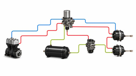
How to Read an Air Brake Diagram: Circuit Guide
How do you read an air brake system diagram? Symbol language, line colours, port codes, circuit split, trailer lines and fault-tracing, step by step.


