AMT Gear Shift Faults: Diagnosis and Repair Guide
A step-by-step diagnostic flow for truck AMT gearboxes that will not shift, drop into neutral or shift slowly, separating air-system faults from electronics.
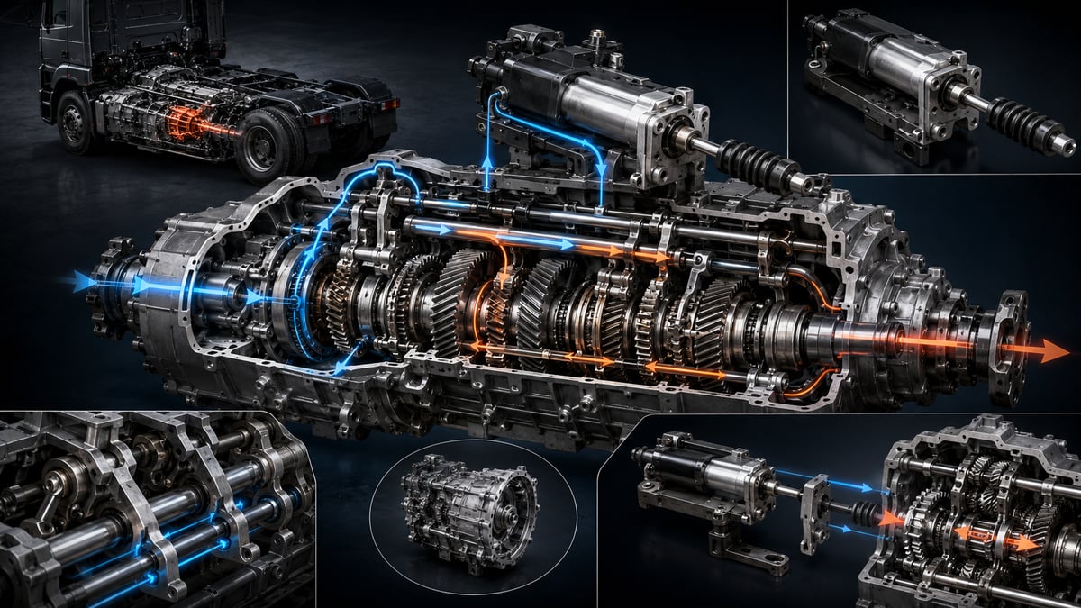
A loaded tractor sits at the foot of a ramp on an early morning start. The driver selects a gear, presses the throttle, and the gear indicator on the dash freezes on a blank dash rather than showing a number. The engine runs cleanly, the brakes hold. Once the truck reaches the workshop, the transmission itself is usually the first thing inspected. Yet on heavy-duty vehicles, most failures to engage a gear have nothing to do with the gear train at all — they get tangled up in the command chain that tells the gearbox to shift: an air circuit that has lost pressure, a solenoid valve with a sticking spool, a pneumatic cylinder leaking past its seal, or a clutch servo whose bite point has drifted. This guide works through failure to shift, dropping into neutral, slow shifts, and fault-code lockouts on automated manual transmissions, starting from the symptom and narrowing the diagnostic path step by step.
What Is an Automated Manual Transmission (AMT)?
An automated manual transmission is, mechanically, a conventional manual gearbox in which gear selection and engagement — along with disengaging and re-engaging the clutch — are carried out by electronically controlled actuators instead of the driver's hand and foot. Inside, the mainshaft, countershaft, gear pairs, dog clutches or synchronizer rings, and shift forks are all still there. What changes isn't the gears — it's who selects them, and how.
For diagnosis, that has one direct consequence: three separate worlds overlap inside every fault search. A mechanical world (gears, forks, dog teeth, synchronizers), a pneumatic world (air generation, conditioning, valves, cylinders), and an electronic world (the control unit, sensors, wiring, data bus). The same symptom can originate in any of the three; diagnosis is nothing more than narrowing down which one is responsible.
How Does an AMT Differ From a Conventional Fully Automatic Transmission?
In a conventional fully automatic transmission, power is taken up through a torque converter working via fluid coupling, and gear ratios come from planetary gearsets braked hydraulically. There is no dry clutch disc, and control is largely hydraulic.
In an AMT, the clutch is still mechanical and mostly dry; because it disengages during every shift, there is a brief torque interruption. What a driver describes as "the truck drops into neutral for a moment when it shifts" is not a fault — it is how this architecture is meant to behave. Control, though, is pneumatic and electronic in most heavy-duty applications: the vehicle is already generating compressed air for the brakes, and the transmission control taps a share of that same air. This is the single most important point for diagnosis: how well the gearbox shifts depends directly on the health of the air system.
AMT, Fully Automatic, and Dual-Clutch Transmissions: Where the Differences Concentrate
Several architectures run side by side in the field, and the names get mixed up easily. To the driver they are all "automatic," but the first thing to check is different for each.
| Architecture | Clutch arrangement | What performs the shift | Torque interruption during shift | First thing checked on a fault |
|---|---|---|---|---|
| Automated manual transmission | Dry clutch, disengaged by a servo | Control unit, solenoid valves and pneumatic cylinders | Present, duration depends on control quality | Air pressure, valve group and actuator feedback |
| Fully automatic (planetary, torque converter) | Torque converter, no dry clutch | Hydraulic control unit and clutch packs | Negligible | Fluid level and condition, hydraulic pressures |
| Dual-clutch arrangement | Two separate clutches, split across odd and even gears | Actuator group, alternating the two clutches | Almost none, shifts overlap | Clutch actuators and learned adaptation values |
The practical takeaway: checking automatic transmission fluid on a box just because it is described as "automatic" wastes time if it is actually pneumatically controlled. Before diagnosis begins, confirm which architecture the gearbox belongs to from its identification plate.
What Chain of Events Does a Single Gear Shift Go Through?
A gear shift is not a single action — it is a sequence of steps completed in a fraction of a second. If any link in that chain is delayed or does not complete, the driver experiences it as "won't shift," "dropped into neutral," or "shifting slowly."
The control unit first decides: engine speed, throttle position, road speed, estimated load, grade, and driver demand are all weighed together. Next, over the data bus, it asks the engine control unit for a temporary torque reduction — without that, the load never comes off the gear teeth. Then the clutch servo disengages the clutch and the current gear moves to neutral, meaning the relevant fork rail is pulled to its center position.
From neutral, the target gear's speed is synchronized. In synchronized boxes the synchro ring handles this; in non-synchronized, dog-clutch heavy boxes, synchronization comes from a transmission brake or from the control unit bringing engine speed to the target value. As the speeds converge, a two-axis movement begins: first selecting the correct fork rail (the select axis), then pushing that rail into the target gear (the shift axis). Pneumatic cylinders perform both movements, and a sensor reports the position of each.
Once the gear is engaged, the control unit sees the position signal reach its target, re-engages the clutch in a controlled manner, and asks for torque to be restored. For the system to be considered healthy, every step in this chain has to complete within its expected time window; if a movement starts but does not finish in time, the control unit aborts, leaves the box in neutral, and logs a fault. That is exactly the picture a driver describes as "it dropped into neutral and locked up."
The Final Link in the Control Chain: How Does the Shifting Cylinder Work?
The shifting cylinder is the last element in the chain, where the control unit's electrical command becomes mechanical motion through compressed air: a double-acting pneumatic actuator that moves the transmission's shift rail or fork in a straight line inside the gearbox housing. The physical force that lines the dog clutch up with the target gear comes from here. In the field it is also called a shift cylinder, or, depending on the job it performs, a range cylinder or a splitter cylinder; the operating logic is the same in every case.
Its construction is simple: a housing, a piston moving back and forth, a rod attached to the piston, a piston seal, a wiper and seal set at the rod exit, a guide bushing, air-inlet fittings, and a sensor that reports position. Some designs house two pistons in a single body, adding a center position for three-position operation; a two-position layout is common in range and splitter stages.
How it works: a solenoid valve feeds air into one chamber of the cylinder while venting the other chamber to atmosphere; the pressure difference between the chambers pushes the piston, the piston rod moves the fork rail, and the dog clutch seats into the target gear. A position sensor tracks the rod; once the control unit sees the expected position reached, it cuts the command and the cylinder is held in its new position under pressure. The cylinder's job is not only to move — it is to stay put once it gets there; if that holding function fails, the vehicle can pop out of gear under load.
That simplicity also makes its failure modes predictable. When the piston seal wears, an internal leak develops between the two chambers: the cylinder still moves, but pushing force drops, and the shift slows down or does not complete. When the rod seal fails, an external leak begins; constant air consumption and a hissing sound around the transmission cover are typical. Dirty or moist air raises friction, so the shift sometimes works and sometimes does not, and this shows up most clearly in cold weather. A poor contact in the position sensor means the control unit cannot see a movement even when it happens, so it treats the shift as failed and cancels it.
Solenoid Valves: The Interface That Turns an Electrical Command Into Air
The control unit cannot feed air to a cylinder directly — solenoid valves sit in between, converting the electrical signal into pneumatic flow. In most designs these valves are grouped into a single control box mounted on the transmission, and the box is treated as one unit together with the electronic board inside it. In some applications the clutch servo and transmission brake valves live in the same block as well.
A solenoid valve does two things: when commanded, it opens a supply path to the relevant chamber; when the command drops, it connects that chamber to exhaust so it can vent. The same operating principle applies to the valves on the vehicle's brake side, and the failure symptoms are surprisingly similar; for how the valve families are laid out and how they typically fail, the truck air brake valves guide offers a useful side-by-side comparison.
Failures fall into three groups. Electrical failures come from a broken coil winding, a short circuit, or connector corrosion; because the control unit can measure the circuit's resistance, it logs these cleanly. Mechanical failures are a spool sticking from deposits or corrosion; the electrical reading looks normal, but air either does not flow or does not cut off when it should. Sealing failures are a valve leaking while it should be closed, leaving unwanted pressure in the opposing chamber and an incomplete shift.
The most misleading of the three, in practice, is the second. Trigger the valve with a diagnostic tool and the coil clicks, the electrical reading is normal — yet the actuator does not move. Before blaming the valve in that case, confirm that supply pressure is actually reaching it; if there is no supply, the fault is not in the valve, it is a stage upstream.
How Does the Clutch Servo Affect Gear Shifting?
In an AMT the clutch itself is a conventional dry clutch; what differs is that the force which disengages it comes from the clutch servo, not a pedal. The servo is a pneumatically powered actuator with a built-in position sensor; the control unit does not just tell it "disengage" — it specifies exactly what position the clutch should be in. A slow, smooth release on pull-away, holding on a grade, and a fast disengagement during a shift are all the same actuator being driven through different speed and position profiles.
The key concept in this architecture is the bite point: the position where the clutch starts transmitting torque. It moves as the friction material wears. The control unit updates it through adaptation routines, but once wear moves outside the adaptation window, the correct position can no longer be found. The result is exactly what a driver describes as "shifts slowly," "jerks on pull-away," or "smells of clutch on a grade" — and these symptoms are often mistaken for a cylinder fault. For wear on the mechanical side of the clutch, pressure-plate friction material and release-bearing behavior, the clutch guide's section on symptoms and service life completes the diagnosis.
On the servo side, look for the same family of faults as on the cylinder: internal and external leaks, a leaking rod seal, position-sensor drift, insufficient supply pressure, and play in the mechanical release fork and bearing. When the release stroke falls short, the clutch never fully disengages; when it does not fully disengage, the load never comes off the gear, and no matter how healthy the cylinder is, the gear cannot go to neutral. Skipping past the clutch and going straight to the actuator group on a "won't shift" complaint is a common and costly mistake for exactly this reason.
Symptom, Likely Node, and First Check in Gear Shift Faults
The table below maps field descriptions to the most likely fault node and the first check that confirms it. Read the urgency column against how the vehicle's movement and safety are affected.
| Symptom | Likely node | First check | Urgency |
|---|---|---|---|
| No gear engages at all, indicator shows a blank | Auxiliary circuit pressure low or no supply to the control box | Pressure gauge on auxiliary circuit, box inlet fitting | Roadside breakdown |
| Vehicle drops into neutral and won't stay in gear | Cylinder holding pressure low, internal leak, or position signal drops out | Static leak test, live position-sensor data | Roadside breakdown |
| Only one gear or gear pair won't engage | Solenoid valve driving that rail, or the select-axis cylinder | Trigger the relevant valve, monitor select-axis position | High |
| Won't shift into the top range, stuck in lower gears | Range cylinder or valve | Range cylinder position signal, leak check around fittings | High |
| Shift is slow, takes a long time to complete | Clutch servo bite point drifted, or weak supply | Adaptation values, servo position profile, system pressure | Medium |
| Won't shift in cold weather, clears up as it warms | Moisture in the air system, dryer efficiency, cylinder sticking | Dryer and tank drain, air-quality check | Medium |
| Constant hissing around the transmission, compressor never stops | Rod seal or fitting leak, internal valve-block leak | Soap-and-water leak trace with engine off, refill-time measurement | High |
| Transmission warning and lockout on the dash, vehicle stuck in neutral | Control unit has entered a safe mode | Read stored fault codes and their occurrence conditions | Roadside breakdown |
Two traps show up when reading this table. First, most symptoms can originate from more than one node; "won't shift" alone does not point to a single part. Second, the record the control unit generates usually describes the result, not the source: a code that says "gear-engage operation timed out" does not mean the cylinder is faulty — it means the movement did not finish within its expected time. Low air pressure, a sticking valve, a leaking seal, and a clutch that does not fully disengage can all produce that same code.
Further reading
For a plain-language technical overview of this subject, see the reference article on Wikipedia. Always confirm specific figures and procedures against the vehicle manufacturer service data.
Why Doesn't the Gear Shift Complete When Air Pressure Is Low?
On a heavy-duty vehicle, compressed air belongs to the brakes first. Air from the compressor passes through the dryer and is then distributed to the circuits by a protection valve, in a defined priority order: the front and rear brake circuits get top priority, the parking-brake circuit follows, and the auxiliary circuit is fed last. Transmission control lives on that auxiliary circuit.
The consequence is direct: if there is a leak somewhere in the system, or the compressor cannot keep up, the first system to lose function is not the brakes — it is the transmission. The protection valve cuts the auxiliary circuit, no supply reaches the control box, and the cylinders cannot move. When you hear "there's no air problem, the brakes hold fine" in the field, remember this: the brakes working proves nothing about whether the auxiliary circuit is supplied.
A sneakier picture appears when pressure sits just above the threshold. There is supply, but it is weak; the cylinder starts to move, the dog clutch approaches the target gear, but cannot complete the final push. The control unit cannot confirm the target position, so it cancels the operation and leaves the box in neutral. What the driver sees is "won't shift, drops into neutral," even though there is nothing mechanically wrong with the transmission. For how to test the air generation, drying, and distribution chain, how to trace leaks, and where to measure pressure, the air brake fault diagnosis guide lays out a step-by-step framework, and a large share of faults that look like transmission problems get resolved inside that same framework.
Where Do You Look for an Air Leak?
A leak in the control circuit shows up, long before it becomes a fault, only as the compressor running more than it should. That is why leak-tracing belongs in scheduled maintenance, not after something breaks. The method is to divide the system into zones and test each one separately.
- Around the control box: the valve block's mounting face, the gasket line, and the exhaust muffler. Continuous air from the exhaust points to a valve leaking internally in the block.
- Cylinder rod seals: the rod exit points of the range, splitter, and gear-select cylinders. A leak here usually shows up together with an oily trace.
- Clutch servo: the housing, rod seal, and supply fitting; a leak here both raises air consumption and disturbs clutch behavior.
- Protection valve and the auxiliary circuit line: the section of the circuit up to the control box; a crack partway along that line can produce every symptom seen at the transmission.
- Air dryer and tanks: a dryer purge valve that keeps blowing, a leaking tank drain cock, and a safety valve stuck open.
The logic of a static leak test is simple: shut the engine off, leave the system at full pressure, and measure the pressure drop after a set time. If the drop is excessive, isolate the circuits one at a time to narrow down the source. Soapy water and a quiet shop give the fastest result; the acceptance limit comes from the OE manual.
Diagnostic Flow: Is the Fault on the Air Side or in the Electronics?
The most expensive mistake in a gear-shift fault is skipping the sequence and going straight to parts replacement. The flow below starts with checks that require no disassembly and narrows the fault down from there; the outcome of each step decides whether the next one is even needed. Every step should be carried out alongside the vehicle's OE service procedure.
- Secure the vehicle on level ground, chock it, and apply the parking brake. Get a detailed account of the complaint from the driver: does it happen cold or warm, loaded or empty, in every gear or one specific gear.
- With the engine running and the system at full pressure, measure auxiliary circuit pressure with a gauge. If the value is below the OE lower limit, stop the diagnosis here; the air generation and distribution chain has to be fixed before the transmission is even considered.
- Shut the engine off, leave the system at full pressure, and read the pressure drop after the specified time. If the drop is excessive, isolate the circuits one by one to narrow down where the leak is.
- Connect the diagnostic tool and read not just current codes but stored history codes and their occurrence conditions. Which pressure, temperature, and gear a code repeats under is the single most valuable clue for narrowing the source.
- In live data, watch clutch servo position, the learned bite-point value, and the position signals of the select and shift axes. If any value sits near the edge of its window, mechanical wear or a shifted calibration is the leading suspect.
- With the vehicle secured and the engine off, trigger the solenoid valves one at a time with the diagnostic tool. If you hear the valve click but the actuator does not move, the fault is not electrical; it is on the supply or mechanical side.
- Confirm that supply pressure is actually present at the control box's inlet fitting by measuring it directly. If there is no supply, the search moves to the auxiliary circuit itself, not the box.
- If you suspect the electrical side, disconnect the connectors, check contact surfaces for corrosion and moisture, and trace the wiring harness along its rub points.
- Check the clutch servo's release stroke and position feedback. If the clutch does not fully disengage, the gear cannot go to neutral, and in that case questioning the actuator group will not get you anywhere.
- Once every precondition above is confirmed, move to the actuator group: watch cylinder movement, check for leaks at the rod seal and fittings, and measure the position sensor.
- After replacing a part, reset adaptation values and run the OE-specified calibration routine; then take a short test drive loaded and unloaded, cycle through every gear, and read the codes again.
The logic behind the flow is that each step proves the precondition for the one after it. Codes read before air pressure is confirmed are misleading; a cylinder cannot be blamed before clutch behavior is confirmed; a new part's outcome cannot be judged before calibration is done. Keep that order, and most gear-shift faults get resolved without disassembly, or with a single part.
Fault Codes and Live Data: What Does Each Record Actually Say?
What the diagnostic tool displays is an observation of the system, not the name of the fault. The control unit only reports what it can measure: a circuit's resistance, a sensor's signal, a movement's duration. That is why the same record can originate from different sources.
| Code family | What the system is actually saying | Where it can mislead | Verification method |
|---|---|---|---|
| Gear-engage operation timed out | Movement started but did not reach target within the expected time | Cylinder is fine, supply pressure is insufficient | Auxiliary circuit pressure and static leak test |
| Position signal outside expected range | Sensor signal is outside the acceptance window | Sensor is fine, mechanical movement fell short | Monitor position in live data during the movement |
| Solenoid circuit open or short | Coil circuit resistance differs from expected | Coil is fine, connector has moisture or corrosion | Measure at the coil terminal with the connector disconnected |
| Clutch adaptation at limit value | Learned bite point is at the edge of its acceptance range | Servo is fine, clutch friction material is worn | Wear indicator and release-stroke measurement |
| System pressure low | Measured supply pressure is below the lower limit | Leak is not in the transmission, it is in another auxiliary consumer | Isolate and test the circuits in sequence |
| Data bus communication loss | A message between control units did not arrive | Transmission is fine, fault is in another unit or the bus itself | Bus termination resistance and a scan of every unit on the network |
| Supply voltage low or fluctuating | The unit's supply is outside the acceptance range | Transmission is fine, battery or charging system is weak | Voltage measurement under load and a chassis-ground check |
The single most useful habit when reading codes is to pull the occurrence conditions along with the code. If the same timeout only repeats on cold starts, suspect moisture and stiction; if it only happens under load, suspect insufficient pressure or clutch wear; if it happens randomly under every condition, an electrical connection is the leading suspect.
What Should and Shouldn't Be Done on the Road When the Gearbox Won't Shift?
A gear-shift fault usually leaves a vehicle stranded, and it is usually in traffic. The first job is not diagnosis; it is getting the vehicle and driver safe: pull off the road if possible, switch on the hazard lights, apply the parking brake, chock the wheels, and place the warning triangle at the distance the regulations require.
What can be tried after that is limited, and all of it stays within what the vehicle manufacturer allows. If low pressure is suspected, letting the engine idle for a while so the system can build up is reasonable. If the control unit has entered a safe mode over a transient fault, cycling the ignition off and back on the way the manufacturer describes resets the system in some cases. Some vehicles define an emergency procedure of their own; that procedure should only be followed from that vehicle's own manual.
What definitely should not be done at the roadside is just as clear. Do not randomly disconnect and reconnect the control box's connectors, do not force-trigger valves, do not try to move cylinder rods by hand or with a lever, and do not loosen any pressurized connection. These interventions are dangerous, and they also destroy the trail of evidence a fault leaves behind.
Why Is Learning and Calibration Mandatory After Actuator Replacement?
In an AMT, the control unit does not manage movement with absolute coordinates; it works from learned references. The clutch bite point, the end positions of the select and shift axes, the exact location of neutral, and the target value for every gear are all numbers stored in the system. Manufacturing tolerance, assembly variation, and wear all shift these values.
When a cylinder, valve block, clutch servo, or clutch assembly is replaced, those references become invalid. The new part's mechanical zero point is not the same as the old one's; a new actuator driven with the old values misses its target, the movement does not complete within the expected window, and the system produces the same fault again. Behind the field phrase "we replaced the part and it's still not fixed" is very often not a bad replacement part, but a calibration that never happened.
The routine's details vary by manufacturer, but the logic is the same: adaptation values are reset with a diagnostic tool, the system runs a defined series of movements on its own to re-measure the end points, and the new references are saved. Certain preconditions have to be met for the routine to run correctly; typically sufficient system pressure, the engine within a specific temperature range, the vehicle stationary, and stable battery voltage are required. A routine started without those preconditions either aborts partway through or saves the wrong reference; the second outcome is worse, because the system reports no fault while behavior stays wrong.
A short learning drive follows calibration; every gear, reverse, and where possible a loaded pull-away should be exercised during it. Once complete, the part replaced, the calibration date, and the new reference values read should all be logged in the vehicle file; on the next fault, that record is the most reliable indicator of how fast wear is progressing.
Technical Metrics and General Reference Ranges
The table below collects the metrics most often needed in the field; these values are not meant for making a decision, they are meant for judging whether a measured result is reasonable.
| Metric | General reference | Interpretation |
|---|---|---|
| Auxiliary circuit priority order | Fed after the brake circuits | The first system to lose supply during a leak is transmission control |
| Gear-shift duration | Sub-second, varies by gear | A duration that stretches out points to pressure, a valve, or the clutch |
| Static leak test metric | Allowed pressure drop over a set time | Acceptance limit comes from the OE manual, do not memorize a number |
| Clutch bite point | Learned value should stay inside the acceptance window | Approaching the edge of the window signals friction-material wear |
| Cylinder seal and O-ring set | Renewed at every disassembly | Reusing them produces internal leaks and incomplete shifts |
| Air quality and dryer cartridge | Per the manufacturer's time or mileage interval | The most common cause of moisture-related valve and cylinder stiction |
| Calibration requirement | On actuator, valve-block, or clutch replacement | Skip it and even a good part will not behave correctly |
| Supply voltage | Within the unit's acceptance range and stable | A weak chassis ground produces random fault codes |
The table's real rule is this: no numeric value in the control system can be used independently of the transmission and chassis code.
Preventive Inspection Program for Fleets
Most gear-shift faults are not sudden; they give small warnings for weeks before crossing a threshold and stopping the vehicle. The job on the fleet side is building an inspection routine that catches those warnings before they become a fault.
- Air build-up time: the time from an empty system to working pressure is logged per vehicle; a lengthening time is the earliest sign of a leak or falling compressor output.
- Tank draining: air tanks are drained regularly, more often in winter. How much water comes out is a direct read on dryer performance.
- Dryer-cartridge discipline: the cartridge is replaced on whichever comes first, mileage or time; the interval is shortened in dusty, humid conditions.
- Static leak measurement: pressure drop is measured and logged at scheduled service; the trend matters more than any single reading.
- Visual inspection around the transmission: the control box, cylinder rod exits, and fittings are checked for oily residue, moisture, and chafing.
- Logging learned values: at service, the clutch bite point and axis end-position values are read and filed; the change between two services shows the wear rate.
- Stored-code scan: history codes are read even when no warning lamp is lit; a recurring code that clears itself is an early warning of a fault still building.
An automated manual transmission is a control chain built on top of a mechanical gearbox, and the health of that chain cannot be separated from the health of the vehicle's air system. That is why a vehicle arriving at the shop with a "transmission fault" diagnosis is usually the start of the diagnostic process, not the end of it. The order is clear: confirm the air supply is sufficient first, then that the clutch fully disengages, then that the valves and actuators are carrying out the command; the transmission's mechanical internals are questioned last. In every case, the current OE service documentation matching the vehicle's engine, transmission, and chassis code governs.
The same driveline electronics also coordinates the retarder that engages during deceleration; for what this function does on the vehicle, see the guide what is a retarder and how does it work.
Shop this part: Shifting Cylinder
Main guide: Heavy-Duty Truck Gearbox: Faults, Replacement & Maintenance
Tags
Frequently Asked Questions
- What is an AMT transmission, and how is it different from a fully automatic transmission?
- An AMT is, mechanically, a conventional manual gearbox; the difference is that gear selection and engagement, along with disengaging and re-engaging the clutch, are carried out by electronically controlled actuators instead of the driver. A conventional fully automatic transmission takes power through a torque converter, has no dry clutch, and is controlled hydraulically. In an AMT the clutch stays dry and mechanical, so there is a brief torque interruption during every shift; control, in most heavy-duty applications, is pneumatic and electronic. That distinction changes the entire diagnostic approach: one calls for checking fluid and hydraulic pressure, the other for checking air pressure and actuator feedback.
- If an AMT won't shift gears, what should you check first?
- The first check is not reading a fault code, it is measuring auxiliary circuit air pressure with a gauge. Transmission control sits on the auxiliary circuit, which is fed after the brake circuits; if there is a leak in the system or the compressor cannot keep up, the protection valve cuts that circuit and the cylinders cannot move. The brakes working normally does not prove the auxiliary circuit is supplied. If pressure is insufficient, neither the codes you read nor any calibration you run afterward will be reliable; the air generation and distribution chain has to be fixed first.
- How can you tell a shifting cylinder has failed on an AMT?
- A shifting cylinder failure shows up in three forms. When the piston seal wears, an internal leak develops: the cylinder still moves but pushing force drops, so the shift slows down or does not complete, and the control unit logs a timeout. When the rod seal fails, an external leak begins, with constant air consumption, the compressor running more, and a hissing sound around the transmission cover. When the position sensor loses contact, the movement can happen but the control unit cannot see it, so it cancels the shift. Verification starts with supply pressure and a static leak test, then moves to watching the position signal in live data.
- Why won't the gearbox shift when air pressure is low?
- Below the threshold, the protection valve cuts the auxiliary circuit off completely and no supply reaches the control box. Just above the threshold, a sneakier picture appears: there is supply, but it is weak, the cylinder starts to move, the dog clutch approaches the target gear, but cannot complete the final push. The control unit cannot confirm the target position, so it cancels the operation and leaves the box in neutral. The driver sees 'won't shift, drops into neutral,' even though the transmission has nothing mechanically wrong with it.
- Why does the truck drop into neutral and not stay in gear while driving?
- The shifting cylinder's job is not only to move a gear into place, it is to hold that position under pressure once it gets there. When holding pressure drops, or an internal leak develops in the cylinder, the dog clutch can walk out of engagement under load and the gear pops out. A momentary loss of the position signal produces the same picture: the control unit cannot confirm the gear is engaged, so for safety it leaves the box in neutral. Verification order: auxiliary circuit pressure, static leak test, then the position sensor's live data.
- What are the symptoms of a failed solenoid valve?
- An electrical failure comes from a broken coil winding, a short circuit, or connector corrosion, and the control unit logs it cleanly because it can measure circuit resistance. A mechanical failure is a spool sticking from deposits or corrosion; the electrical reading looks normal, but air either does not flow or does not cut off when it should. A sealing failure is a valve leaking while it should be closed, causing unwanted pressure in the opposing chamber and a weak shift. The most misleading case is when the diagnostic tool triggers the valve, the coil clicks, the reading is normal, yet the actuator does not move; before blaming the valve, confirm that supply pressure is actually reaching it.
- Why does the shift lag and why does the truck jerk on pull-away?
- These symptoms usually trace back to the clutch servo and its bite point, the position where the clutch starts transmitting torque, which moves as the friction material wears. The control unit updates it through adaptation routines, but once wear moves outside the adaptation window, the correct position can no longer be found, producing a slow shift, a jerky pull-away, or a struggle to hold on a grade. Check the adaptation values, release stroke, and any clutch wear indicator. A leak or weak supply on the servo side can produce the same picture.
- Why won't the transmission shift in cold weather?
- Most shift problems that show up in the cold and clear once things warm up are rooted in moisture. Once the air dryer's cartridge saturates, water passing into the system condenses overnight on valve spools and cylinder walls; it freezes by morning, blocking movement, and the symptom disappears once it thaws during the day. Dirty, moist air also leaves corrosion and deposits that raise friction permanently. Regular tank draining and replacing the dryer cartridge on schedule largely eliminates this fault family.
- Is calibration required after replacing an actuator or valve block?
- Yes. The control unit manages movement using learned references, not absolute coordinates: the clutch bite point, the end positions of the select and shift axes, and the location of neutral are all stored values. Once a part is replaced, those references no longer apply; a new actuator driven with the old values misses its target and the system faults again. Behind the field phrase 'we replaced the part and it's still not fixed' is very often a calibration that was never run. The routine is carried out with a diagnostic tool once preconditions like system pressure and battery voltage are met, followed by a short learning drive.
- How should a vehicle with a transmission fault be towed?
- Before towing, confirm the transmission is actually in neutral; with control supply cut, you cannot assume the box is in neutral just because the driveline feels loose. Towing it while still in gear can permanently damage the gear set and lubrication. Many manufacturers require the driveshaft to be removed or the drive axles lifted beyond a certain towing distance. If there is any doubt, move the vehicle with an axle-lift recovery unit, and always follow the recovery section of the vehicle's OE manual.
Related Articles
What Is a Retarder? How Does It Work and What Does It Do?
What is a retarder, and how does it work? Hydraulic vs electromagnetic retarders, stages, engine-brake differences, faults and maintenance for heavy trucks.


