What Is a Retarder? How Does It Work and What Does It Do?
What is a retarder, and how does it work? Hydraulic vs electromagnetic retarders, stages, engine-brake differences, faults and maintenance for heavy trucks.
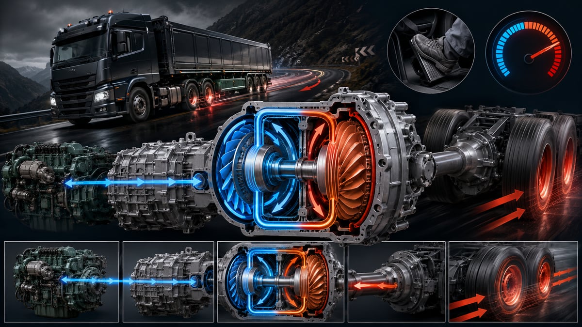
A loaded tractor-trailer crests a long descent with the driver's foot already resting on the brake pedal. For the first few kilometres nothing seems wrong; halfway down the grade the pedal starts to sink further, the truck slows less for the same push, and the smell of hot brake linings drifts into the cab. Another truck completes the same descent at a steady speed with the pedal barely touched. The difference is that the second truck is converting its kinetic energy into heat somewhere other than the brake linings. This guide treats the retarder that does that job not as an "extra brake" but as an energy-management component sitting between the driveline and the cooling system.
The wear-free auxiliary brake concept and what a retarder is
A retarder is a braking system in heavy commercial vehicles that operates independently of the service brake and is considered "wear-free" because it has no friction surface that wears down. It converts the vehicle's kinetic energy directly into heat, hydraulically or magnetically; it does not bring the vehicle to a stop, but reduces its speed or holds it steady on a descent.
In English the system is simply called a retarder; technical literature also refers to it as an auxiliary brake or endurance brake (continuous brake). The word "continuous" is the key distinction: the service brake is built for short, high-power stops, while the retarder is built for long, moderate-power slowing. The two are not rivals; they are two different tools within a single division of labour.
Clarifying what a retarder is not removes half of the misuse seen in the field. A retarder is not a stopping system; its effect diminishes as speed drops and it cannot bring the vehicle to a complete halt. It does not replace the parking brake, nor is it an emergency-braking device. Its job is to keep the service brake in reserve so that it is available at full capacity the moment it is actually needed.
Division of labour between the retarder and the service brake
The service brake is designed to dissipate high power in a very short time: the drum or disc absorbs the heat generated by lining friction into its own mass and sheds it to the air. This design is excellent for stopping at a junction; used continuously on a ten-kilometre descent, however, it builds up heat faster than it can shed it. The retarder fills exactly this gap: its power is lower than the service brake's, but because it can continuously dump its heat into the engine cooling circuit or into the air, it can run for hours. On a well-managed descent the whole grade is handled by the retarder, and the service brake is used only for speed correction and the final stop.
Why does the retarder exist? Brake fade and the service brake's heat limit
What happens on a descent is a simple energy conversion. The potential energy a vehicle gains from altitude must be converted entirely into heat for as long as speed is held constant. On a long grade, a combination weighing close to forty tonnes sheds an amount of heat far too large for a handful of linings and a drum to absorb; without a retarder, the only place for that energy to go is the friction surfaces themselves.
As lining temperature rises, the coefficient of friction drops. The driver describes this as "the brakes aren't holding"; the technical name is brake fade — the brake losing effectiveness with heat. In drum systems a second mechanism compounds it: the heated drum expands in diameter, the shoes have to travel further to make contact, and the same air pressure produces less braking force. When the two effects stack up, the loss is felt suddenly; the pedal goes soft, the vehicle accelerates, and the only option left is downshifting — which, in a vehicle that has already picked up speed, is often no longer possible. Our guide on brake safety on long descents and what causes brake fade walks through the decision points on the driver's side of this chain step by step.
This is the retarder's reason for existing: to take heat off the friction surfaces and move it into the cooling circuit or into the air. Its side benefits matter to fleet economics too — lining and drum life extend noticeably, and because descent speeds stay stable, journey times become more predictable. There is a regulatory dimension as well: braking regulations define an endurance test requiring the vehicle to hold its speed on a long grade using only its wear-free braking system; for certain classes of coach and tractor unit, a retarder is therefore not an option but a type-approval requirement.
How does a hydraulic (hydrodynamic) retarder work?
A hydraulic retarder consists of a rotating, bladed rotor facing a fixed stator. The rotor flings the oil filling the space between them toward the stator; the oil's impact and rebound generates a torque that pushes back against the rotor. The vehicle's energy is converted into heat by this internal friction and passed into the oil.
The elegance of the system lies in how braking intensity is set. The rotor and stator never touch; only oil sits between them. Braking torque is determined by the volume of oil admitted into the working chamber. The stage selected on the control lever is passed, via the control unit, to a proportional valve; using air or oil pressure, the valve fills the chamber partially or fully. When the stage is switched off, the chamber is drained, the rotor spins freely in the empty chamber, and drag losses fall to almost zero. Because there is no wearing surface, the system's service life depends far more on the condition of the oil and the cooling than on how often it is used.
The path the heat follows is the key to understanding a hydraulic retarder. The energy first passes into the oil, the oil sheds its heat to the engine coolant across a heat exchanger, the coolant travels to the radiator, and the heat is finally rejected to the air there. In other words, a hydraulic retarder shifts the braking load off the brake system and onto the cooling system; in a vehicle whose cooling is already compromised, the retarder loses power along with it.
When the control lever is pulled, braking does not reach its full value instantly; filling the working chamber takes a moment. This delay is not a fault — it is a sign that the retarder is designed for planned slowing rather than sudden manoeuvres. In heavy-duty applications, hydrodynamic units are most often OE solutions from manufacturers such as ZF and Voith, and are delivered integrated into the vehicle manufacturer's transmission and brake electronics.
How does an electromagnetic retarder work?
An electromagnetic retarder consists of steel rotor discs turning inside the magnetic field produced by fixed coils. As the discs rotate through the field, eddy currents form inside them; the opposing field these currents create resists the rotation and produces braking torque. Energy is converted directly into heat in the discs, and that heat is shed to the air through cooling fins.
Here too there is no contact surface; braking happens magnetically, across the narrow air gap between the rotor and the coils. Stages are set by the number of coil groups energised: the first stage brings in one group, the top stage brings in all of them.
The distinguishing feature of this design is that it places no load on the cooling system and needs no separate oil circuit. In exchange, it carries two costs. The first is electrical: the coils draw a substantial current from the battery and charging system, so battery health, alternator capacity, cable cross-section, and connector contact quality directly determine braking power. The second is heat: the rotors shed heat only to the air, so on a long descent, once the discs get hot enough, the torque produced drops. The units are also heavy, and because they are mounted on the driveline, shaft balance becomes a maintenance item.
Comparison of hydraulic and electromagnetic retarders
| Criterion | Hydraulic (hydrodynamic) retarder | Electromagnetic retarder |
|---|---|---|
| Operating principle | Oil friction between rotor and stator | Eddy currents in rotating discs |
| Braking adjustment | Oil volume admitted to the working chamber | Number of coil groups energised |
| Where the heat is rejected | Oil, heat exchanger, engine coolant, radiator | Directly to air via rotor fins |
| Load placed on the vehicle | Cooling system capacity is the limiting factor | Battery, charging system and wiring are the limiting factor |
| Continuous-duty behaviour | Stable for long periods if cooling is adequate | Torque drops somewhat as discs heat up |
| Maintenance items | Oil, filter, heat exchanger, proportional valve, air circuit | Connectors, contactors, cabling, air gap, shaft balance |
| Typical fault origin | Neglected oil and cooling, blocked valve | Corroded connector, low voltage, blown fuse |
Primary and secondary retarders: where placement matters
What matters more than a retarder's power is where in the driveline it is fitted; that is what defines how it feels to drive. There are two basic placements, and they behave very differently at low speed.
A primary retarder sits on the engine side; its braking torque enters ahead of the transmission. Because the torque is multiplied by the gear ratio, it produces noticeable slowing even in low gears and at low road speed. The cost is that its effect depends on the gear and clutch: when the clutch is disengaged, braking is interrupted. Its heat enters the engine cooling circuit.
A secondary retarder sits at the transmission output or on the driveshaft; it applies torque directly to the drive axle. It is independent of gear and clutch and keeps braking even during a gear change. In exchange, its effect depends on driveshaft speed: as road speed drops, braking torque falls off. This is the most common arrangement on trucks, tractor units and intercity coaches.
| Feature | Primary (engine side) | Secondary (transmission output / driveshaft) |
|---|---|---|
| Connection point | Between the engine and the clutch | Transmission output or driveshaft line |
| Affected by gear ratio | Torque is multiplied by the gear ratio | Independent of gear |
| While the clutch is disengaged | Braking is interrupted | Braking continues |
| Effect at low speed | Remains high in low gears | Diminishes as speed drops |
| During a gear change | A brief gap in braking occurs | Uninterrupted slowing |
| Typical application | Stop-start city buses, heavy work vehicles | Long-haul tractor units, intercity coaches |
The difference between the retarder, the engine brake, and the exhaust brake
This is the point most often confused in the field. All three slow the vehicle without using linings, but they dissipate energy in different places. An exhaust brake closes a flap in the exhaust line to create back-pressure; the engine turns into a compressor, and the work the pistons spend compressing air becomes the resistance that slows the vehicle. What is usually called an engine brake — a compression-release system — goes a step further: it briefly opens a valve at the top of the compression stroke to vent the compressed air, so the energy spent compressing it can no longer be recovered on the expansion stroke, and braking power rises noticeably. Both depend on engine speed: strong in a low gear at high RPM, weak in a high gear at low RPM. Our guide on exhaust and engine brakes details the typical problems on the flap, cylinder and valve side of these two systems.
The retarder, by contrast, is independent of combustion and engine speed; its power is generally higher than the exhaust or engine brake, it runs almost silently, and it rejects heat into the coolant or the air. In modern vehicles these systems are not alternatives to one another but combined stages on a single control lever: the engine brake engages at the lower stages, the retarder at the upper ones.
| Criterion | Exhaust brake | Engine (compression-release) brake | Retarder |
|---|---|---|---|
| Operating principle | Back-pressure from an exhaust flap | Compressed air vented through a valve | Oil friction or eddy currents |
| Where the energy goes | Exhaust gas and engine structure | Exhaust gas and engine structure | Retarder oil and coolant or air |
| Depends on | Engine speed and gear | Engine speed and gear | Road speed or driveshaft speed |
| Relative braking power | Low | Moderate | High |
| Noise level | Noticeable drone | Sharp, hard bark | Nearly silent |
| Wearing part | Flap shaft, cylinder, seal | Valve mechanism components | No friction surface |
| Role on a long descent | Supporting | Supporting and reinforcing | Primary source of slowing |
Further reading
For a plain-language technical overview of this subject, see the reference article on Wikipedia. Always confirm specific figures and procedures against the vehicle manufacturer service data.
Stages and control: how does a retarder engage?
In most vehicles the retarder is operated in stages using a steering-column stalk or a dash-mounted switch. The number of stages varies by vehicle; three to five stages is common, with the top stage corresponding to full capacity. The stalk is usually paired with a cruise-control-type function as well: the driver sets a target speed for the descent, and the control unit manages the stages itself.
The second way the retarder engages is through the brake pedal. On many vehicles, the first part of pedal travel activates the retarder rather than the service brake; only when the driver presses further do the linings engage. This blended-braking logic is a quiet gain in lining life during everyday driving. The retarder is not always available, though: it cuts out instantly if wheel lock-up is detected or if the electronic stability system intervenes. The reason is straightforward — a retarder brakes only the drive axle, and on a low-grip surface this single-axle braking can cause the rear of the vehicle to swing out.
Do the brake lights come on when the retarder is engaged?
Not at every stage. Regulations tie the brake lights to a defined deceleration threshold; at low stages the deceleration produced can fall below that threshold, so the driver behind may not see from the lights that the vehicle is slowing. In heavy traffic it is worth watching following distance in the mirror rather than relying on the lights.
How to use the retarder on a long descent
The rule never changes: speed and gear are set correctly before the descent begins. Once a descent has started in a vehicle that has already picked up speed, downshifting is often no longer possible, leaving only the service brake — which is now doomed to overheat — as the sole remaining option.
- Before reaching the top of the descent, reduce speed and select a gear close to the one you would use climbing the same grade loaded; if in doubt, choose the lower gear.
- Engage the retarder starting from a low stage; braking takes a few seconds to build up, so allow for this delay.
- If speed keeps rising, increase the stage. If a descent cruise-control function is fitted, set the target speed and let the system manage the stages itself.
- Keep the service brake in reserve. When needed, use short, firm presses to bring speed down and then release the pedal; holding it lightly applied continuously is the fastest way to heat up the linings.
- Watch the instrument cluster. If coolant or retarder temperature is climbing, the system will reduce its own power automatically; don't wait for that — reduce speed yourself and drop another gear if necessary.
- As soon as the surface becomes slippery, drop the stage or switch the retarder off; avoid braking the drive axle hard through corners at a high stage.
- At the bottom of the descent and at low speed the retarder's effect diminishes; the final stop is always made with the service brake, and holding a parked vehicle is always the parking brake's job.
Heat management: what does a retarder load onto the cooling system?
In a hydraulic retarder, the upper limit on braking power is set not by the unit itself but by the vehicle's capacity to reject heat. On a descent, the cooling system does two jobs at once: it carries away the engine's own waste heat and the heat generated by the retarder, both through the radiator. The control unit monitors coolant and retarder oil temperature; once a threshold is crossed, it reduces braking torque in stages. The driver describes this as "the retarder held, then let go," and blames the retarder — when the real problem is usually on the cooling side.
For this reason, retarder maintenance cannot be considered separately from cooling-system maintenance. A radiator with a clogged core, a slipping fan clutch, a worn-out coolant pump, a thermostat that opens late, and coolant past its service life all reduce retarder capacity before the engine itself shows any symptom. There is a further, separate risk at the heat exchanger: if the surface separating retarder oil from coolant is breached, the two circuits mix; an unexplained change in coolant level, an oil film on top of the reservoir, and transmission oil turning a milky coffee colour are the telltale signs.
In an electromagnetic retarder the heat path is shorter, but the limit still exists. A unit coated in dirt with blocked airflow heats up its discs quickly and loses torque; sustained use at a high stage also increases the risk of disc warping.
Retarder failure symptoms, causes and diagnosis
The most common mistake in retarder diagnosis is blaming the unit without looking at the system as a whole. A retarder operates on inputs from air or oil pressure, the electrical supply, the control-stalk signal, the brake electronics, and the cooling system. If braking doesn't come, the fault can sit inside the unit itself, or in any one of these inputs; diagnosis should always start with the cheapest and most likely items: fuses, connectors, air leaks, fluid level and temperature.
| Symptom | Likely mechanism | Verification / check |
|---|---|---|
| No braking at any stage | Supply, fuse, stalk signal, or main valve fault | Read fault codes, measure stalk signal and supply voltage |
| Only some stages hold | A coil group or contactor disabled (electromagnetic) | Monitor current draw and contactor behaviour stage by stage |
| Braking starts, then fades within minutes | Thermal limit: cooling capacity insufficient or oil too hot | Monitor coolant and retarder oil temperature from live data |
| Retarder or oil-temperature warning on the dash | Blocked radiator, weak fan, low coolant, dirty heat exchanger | Check radiator and fan, test the cooling circuit |
| Retarder stays engaged on its own | Stuck proportional valve, air leak, or faulty stalk switch | Monitor valve and stalk signal live, leak-test the air circuit |
| Oil in the coolant, water traces in transmission oil | Heat-exchanger breach, the two circuits mixing | Pressure-test both circuits, inspect oil and coolant samples |
| Rapidly increasing vibration or drone | Driveshaft balance loss, centre-bearing or rotor damage | Check shaft balance, flange torque, and bearing clearance |
Step-by-step retarder diagnostic flow
- Have the complaint described precisely: at which stage, at what speed, after how long, and on what kind of route it appears.
- Read the fault codes and freeze-frame data; even with no code present, move to live data, since a share of retarder faults progress without ever setting one.
- Test the supply side: fuses, main connectors, earth/ground connection, battery voltage and the charging system. On electromagnetic units, low voltage is the most common cause of what looks like "the unit has failed."
- Monitor the control stalk's signal and the brake-pedal initial-travel switch stage by stage; if the signal isn't reaching the unit, there is no point looking at the unit itself.
- On a hydraulic system, assess oil level and condition; on air-controlled units, measure supply pressure and check for leaks — a small leak often shows up only at the top stage.
- Monitor temperature data under load: how coolant and retarder temperature trend during a road test shows whether torque is dropping because of a thermal limit.
- On an electromagnetic unit, measure the air gap between rotor and coils using the manufacturer's method, and inspect the rotor surface for discolouration and cracking.
- After the repair, clear the codes and verify every stage with a loaded road test; a stationary workshop test will not reveal thermal behaviour.
Retarder maintenance: oil, filter, cabling and connectors
A retarder has no wearing surface, so its maintenance is not about replacing parts but about preserving operating conditions: oil and filter on a hydraulic system, connection quality on an electrical one, and cooling and mounting health on both.
A significant share of hydraulic retarders integrated into the transmission share the transmission's own oil. The implication is clear: in a vehicle that uses its retarder, transmission oil sees higher temperatures, ages faster, and an off-specification oil affects the retarder as well as the gears. The oil and filter interval should therefore follow the value the manufacturer specifies for the retarder-equipped configuration. Readers who want the full picture should read our heavy-duty truck gearbox guide alongside this one for oil selection, sealing, and heat behaviour.
- Oil level and condition: at scheduled service, level is measured at the temperature and vehicle position the manufacturer specifies; colour, smell and any trace of water are assessed.
- Oil and filter change: the interval for the retarder-equipped configuration applies; the filter is not a consumable to skip but the component that protects the proportional valve.
- Leaks and cooling: the unit housing, fittings and heat-exchanger connections are checked dry; radiator core, fan-clutch operation and coolant condition are part of retarder maintenance.
- Electrical connections: main supply cables, earth/ground points and connectors are checked for corrosion, looseness and heat marks; contactor contact is tested.
- Air circuit and mounting: the supply line, valve and fittings are inspected for leaks; on units mounted on the driveshaft line, flange bolts, the centre bearing and shaft balance are assessed.
The most common habit that shortens a retarder's life is running it continuously at a high stage with a poorly maintained cooling circuit. Second most common is an off-specification oil; third, on electromagnetic units, is neglected connector maintenance — a corroded contact point first causes lost stages, then contactor damage, and eventually a burned-out coil.
Technical values and check points
There is no single "standard value" table for retarders; stage count, temperature thresholds, oil specification and air gap all vary by vehicle manufacturer, unit type and transmission combination. The table below is therefore not a numeric recipe but a framework showing where each figure should be sourced.
| Check point | General reference | Source and effect of the value |
|---|---|---|
| Oil type and volume | Shared circuit with the transmission, or a separate circuit | OE specification is authoritative; the wrong oil reduces both braking torque and unit life |
| Oil and filter interval | Specific to the retarder-equipped configuration, shortened | Taken from the service manual; not the same as the interval for a vehicle without a retarder |
| Thermal limitation threshold | Temperature limit managed by the control unit | Once exceeded, torque is reduced in stages; this is protective behaviour, not a fault |
| Air gap (electromagnetic) | Narrow tolerance band set by the manufacturer | Measured with feeler gauges; a widened gap noticeably reduces braking torque |
| Supply voltage and current | Assessed against the vehicle's own electrical system | If the battery and charging system are weak, the upper stages cannot deliver full power |
| Driveshaft balance and flange torque | Manufacturer torque and balance values | Taken from the service manual; prevents vibration and bearing damage |
Where does the retarder sit in the driveline and brake chain?
Treating the retarder as a stand-alone accessory makes most of its faults hard to understand. The system sits at the intersection of three chains. The first is the driveline: the retarder transmits its torque to the drive axle through the driveshaft and differential, which is why shaft balance, centre-bearing and flange health are directly a retarder concern. The second is the cooling system: on hydraulic units, the radiator, fan, coolant pump and thermostat set the upper limit on braking power. The third is the brake electronics: the retarder, the service brake, the engine brake and the anti-lock systems are all managed together within a single deceleration strategy.
This three-part structure guides diagnosis. If braking torque never arrives at all, the control and supply side — the third chain — is examined first. If braking comes but doesn't hold, attention turns to the second chain, cooling. If vibration or noise accompanies it, the first chain, the mechanical connection, comes to the front. The neighbouring links also change behaviour: a weakened engine brake puts more load on the retarder, while a worn service brake makes the retarder appear less effective than it actually is.
In short, the retarder is the endurance side of braking in a heavy commercial vehicle: the service brake stops it, the retarder holds its speed. Choosing the right stage, selecting the right gear before the descent, a well-maintained cooling circuit and clean electrical connections are what keep this side standing. For any question of measurement, adjustment or interval, the current OE service documentation specific to the vehicle's engine and chassis code is authoritative.
Shop this part: Retarder
In-depth technical guide: For fault diagnosis, step-by-step replacement and service intervals: Truck Retarder: Faults, Replacement & Maintenance Guide
Main guide: Heavy-Duty Truck Gearbox: Faults, Replacement & Maintenance
Tags
Frequently Asked Questions
- What is a retarder and what does it do?
- A retarder is a braking system on heavy commercial vehicles that works independently of the service brake and doesn't wear because it has no friction surface. It converts the vehicle's kinetic energy into heat hydraulically or magnetically to reduce speed or hold it steady on a descent. Its job isn't to stop the vehicle — it's to keep the service brake in reserve so the linings don't overheat.
- How does a retarder work?
- In a hydraulic retarder, a bladed rotor flings oil against a fixed stator, and the resulting internal friction slows the vehicle; the heat passes from the oil through a heat exchanger into the engine coolant. In an electromagnetic retarder, steel discs spinning inside a field created by fixed coils generate eddy currents that resist rotation, and the heat goes straight to the air. Neither type has a contact surface that wears.
- What's the difference between a retarder and an engine brake?
- The engine brake and exhaust brake dissipate energy inside the engine and depend on engine speed — strong in a low gear at high RPM, weak in a high gear. The retarder works independently of combustion, produces its braking at the transmission output or on the driveshaft, and is usually more powerful. In modern vehicles the two are combined as stages on a single control lever.
- Does a retarder bring the truck to a stop?
- No. A retarder's braking effect diminishes as speed drops and cuts out entirely below a certain road speed. The final stop is always made with the service brake, and holding a parked vehicle is the parking brake's job.
- Does a retarder extend brake lining life?
- Yes. Because the retarder takes on most of the slowing on long descents and in traffic, the linings and drums run much cooler and wear far less. On many vehicles, the first part of brake-pedal travel activates the retarder rather than the service brake, spreading this benefit into everyday driving.
- Which is better: a hydraulic retarder or an electromagnetic retarder?
- Both do the same job; they just pay the cost in different places. A hydraulic retarder sheds heat into the engine coolant — it stays stable for long periods if the cooling system is well maintained, and it usually comes integrated with the transmission. An electromagnetic retarder places no load on the cooling system but depends on the battery, charging system and wiring, and its torque drops somewhat as the discs heat up.
- Can you use the retarder on a wet or snowy road?
- Not at a high stage on a slippery surface. A retarder applies its braking torque only to the drive axle, so on a low-grip surface it can cause the rear of the vehicle to step out. In these conditions, drop the stage or switch it off; most vehicles cut the retarder automatically the moment wheel lock-up is detected.
- What should I check if the retarder stages aren't holding?
- Check the supply and control side before suspecting the unit itself: fuses, main connectors, earth connection, battery voltage and the control stalk's signal. Only some stages working usually points to a disabled coil group or contactor on an electromagnetic unit. On air-controlled hydraulic units, a small air leak often only shows up as reduced capacity at the top stage.
- Why does the retarder lose power after a while?
- In a hydraulic retarder, the upper limit on braking power is set by the vehicle's ability to reject heat. Once coolant or retarder oil temperature crosses a threshold, the control unit reduces torque in stages — this is a protective response, not a fault. A blocked radiator, a weak fan clutch, a worn coolant pump or coolant past its service life all bring that limit on much sooner.
- How is a retarder maintained, and does the oil need changing?
- Most hydraulic retarders integrated into the transmission share the transmission's own oil, so the oil and filter interval should follow the value the manufacturer specifies for the retarder-equipped configuration. Other maintenance items are the cooling circuit, a check for leaks, electrical connectors and contactors, and flange, centre-bearing and balance checks on the driveshaft line. For torque, air gap and oil volume, the current OE service manual specific to the vehicle's engine and chassis code is authoritative.
Related Articles

What Is Brake Fade? Long-Descent Braking Strategy
What causes brake fade, and how do you use the engine brake, exhaust brake, and retarder on a long descent? A heat management guide for heavy trucks.
What Is an EGR Valve? Failure Symptoms and Cleaning (Heavy Commercial Vehicles)
What is an EGR valve? How it works, why it clogs, failure symptoms, diagnosis steps, and cleaning limits for heavy commercial vehicles.
Water Separator Filter: Diesel Water Drain & Warning
Where does water get into diesel fuel, how does a water separator work, and what should you do when the warning light comes on? A heavy-duty vehicle guide.


