What Is an Air Processing Unit? Role, Faults & Care
What is an air processing unit and how does it work on a truck? Drying, pressure regulation, fault diagnosis, and maintenance explained.
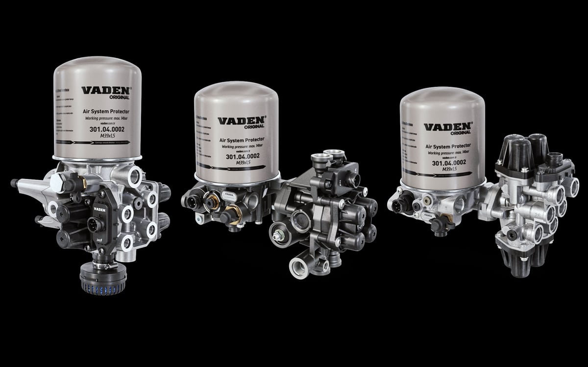
Turn the key on a cold morning and the compressor kicks in straight away: the needles on the gauges climb, and the front and rear brake circuits fill within a few minutes. Yet the suspension stays flat, the cab won't lift, and the parking brake refuses to release. The driver's first guess is usually a leaking air bag, but every line checks out sound. The fault sits inside the part that bridges the compressor and the reservoirs — a single aluminium housing from the outside — where the section feeding the auxiliary circuit simply hasn't reached its own opening pressure yet, so it never let the air through. This guide treats the combined unit that dries, regulates, and shares out that air not as one spare part, but as a piece of priority logic.
Why can't compressed air be used raw on a commercial vehicle?
The compressor is simply an air pump driven off the engine, and what it draws in is ordinary roadside air — carrying moisture, dust, and road grime. Compressing that air shrinks its volume and concentrates the water vapour inside it; a trace of oil vapour also rides along from the cylinder wall's oil film. The compressed air comes out hot, cools as it travels down the lines, and drops the moisture it was carrying as liquid. Left untreated, then, the air leaving the compressor is a mixture that carries water and oil straight into the reservoirs.
That mixture does damage on four fronts. Water starts corrosion inside valve bodies and, in winter, freezes solid enough to lock up brake valves. Oil swells and hardens rubber seals and diaphragms, and saturates the cartridge's drying bed well ahead of schedule. Solid particles grind away at precision valve seating surfaces like sandpaper. The fourth is purely mechanical: if the pressure the compressor builds isn't capped, lines and air bags end up loaded beyond their design limit.
That is why heavy commercial vehicles always place a processing stage between the compressor and the reservoirs. That stage does four jobs at once: it cleans the air, removes its moisture, regulates and caps its pressure, and shares out what's left across circuits that don't carry equal safety weight. For the full chain from compressor to brake chamber, see our air brake systems guide; this article focuses only on the processing and distribution stage of that chain.
What is an air processing unit, and which jobs does it combine in one housing?
An air processing unit is a combined pneumatic component that packs drying, pressure regulation and limiting, and priority-based distribution to isolated brake and auxiliary circuits into a single housing. It does the job of a separately sold air dryer, pressure regulator, and multi-circuit protection valve all at once, routing everything through shared internal channels instead of external plumbing.
The industry knows this unit by more than one name. The abbreviation APU (air processing unit) is standard in English-language documentation; electronically controlled versions are labelled EAC (electronic air control). Depending on the manufacturer, you'll also see it listed as an air preparation unit or an air drying and distribution unit. Original equipment makers such as Wabco and Knorr-Bremse each catalogue it under their own product names, but the function underneath is identical.
A typical unit packs in the following functions: an inlet section that strips out coarse water and oil droplets from the incoming air, a drying cartridge holding the moisture-absorbing bed, a regeneration and purge valve that back-flushes the cartridge on cut-out, a pressure regulator that governs whether the compressor runs loaded or unloaded, a safety valve that backs up a failed regulator, a multi-circuit protection section that feeds circuits in sequence and isolates them from one another, a pressure-limiting stage that supplies the auxiliary circuit at a lower pressure, a heater that keeps the purge side from freezing, and, on electronic versions, pressure sensors and a control module. The practical upshot is this: when a fault shows up, the question isn't "is the part broken?" but "which section is broken?"
Why put it all in one housing? The connection and leak burden of a split setup
In the classic split layout, the compressor outlet feeds the dryer first, the dryer outlet then connects to the wet tank or straight into the protection valve, the pressure regulator ties back to the compressor on its own control line, and the multi-circuit protection valve sits on its own bracket somewhere on the chassis. Every part has its own inlet and outlet fittings, its own runs of pipe in between, and its own share of vibration to absorb. Every fitting, in turn, is a seal that loosens over time — and the more connections there are, the higher the odds of a leak.
A combined unit moves most of those intermediate lines into cast channels inside the housing itself, leaving only the compressor inlet, the circuit outlets, the purge port, and — where fitted — the regeneration tank connection exposed to the outside. The second gain is packaging: under-cab space is tight, and a single-bracket housing simplifies the whole installation. The third is calibration integrity: the protection section's opening and closing pressures and the regulator's cut-out point are set at the factory relative to one another, so you never end up pairing mismatched components on the job.
There's a trade-off. In a split layout, the failed part is simply swapped on its own; in a combined unit, the fault stays hidden inside the housing, and pinning down the right section takes measurement and flow observation. A complete unit also costs more than a single valve. That's why manufacturers offer sectional repair kits and standalone cartridges for most of these units.
What's inside the unit, and what does each section do?
The table below lines up the functional sections inside the housing, what each one does, and the symptom you'll see from outside when it fails. It also reads in reverse for diagnosis: start from a symptom and use it to find which section to check.
| Internal section | Task | Symptom when faulty |
|---|---|---|
| Inlet and pre-separation section | Separates coarse water and oil droplets from the hot air coming off the compressor | Cartridge saturates early, oily sludge builds up in the reservoirs |
| Drying cartridge and moisture-absorbing bed | Holds the water vapour in the air, sends dry air on to the circuits | Water in the reservoirs, valves freeze and seize in winter |
| Regeneration and purge valve | Back-flushes the cartridge at cut-out, vents the condensate | Continuous air blow-off, or no purge sound at all on cut-out |
| Pressure regulator section | Sets the cut-out and cut-in pressure, unloads the compressor | Pressure never cuts out, cuts out far too early, or the safety valve lifts |
| Multi-circuit protection section | Feeds circuits in priority order and isolates them from each other | One circuit never fills, or circuits drain together |
| Backflow check seats | Stop a leaking circuit from draining the sound circuits | All gauges drop together on a parked vehicle |
| Pressure-limiting stage | Supplies the auxiliary circuit at a lower pressure than the main circuits | Auxiliary equipment runs under- or over-pressured, wears out early |
| Heater and thermostatic switch | Prevents ice forming on the purge side | No air in the morning in winter, clears itself once it warms up |
| Pressure sensors and control module | Monitors circuit pressures, runs the purge cycle, logs faults | Dash warning, fault code, adaptive cut-out not working |
Not every product includes all of these sections: basic mechanical units skip the sensors and control module entirely, and some designs leave the pressure-limiting stage to a separate valve. Check which functions are actually built in against the technical documentation for the vehicle's equipment code.
Multi-circuit protection valve logic: opening, closing, and backflow protection
The unit's defining section is the protection stage that shares out dry air across the circuits. It isn't a simple distribution box: every outlet port carries a spring-loaded seat and a backflow check, and between them these two elements define three core concepts.
Opening pressure is the value at which a circuit outlet opens and starts being fed; below that value the outlet stays shut and no air reaches the circuit. Closing pressure is the value at which that same outlet shuts again once supply drops, and it's the system's safety promise: it sets the residual pressure guaranteed to stay in the sound circuits when one circuit fails completely. Backflow protection is the check-valve function that stops air from a healthy circuit draining back toward a leaking circuit or the common supply side.
In practice, that means: if a hose bursts on the auxiliary circuit, air escapes from that point and pressure falls to the closing value. At that point the auxiliary outlet shuts, the backflow check holds the sound circuits' air in, and the vehicle stays able to brake. There's one more difference between designs: some protection sections are fully isolating, others allow limited backflow. The second behaviour is misleading during diagnosis — a small leak in one circuit gets masked for a long time by top-up from the neighbouring circuit, and only shows up once the compressor's run time stretches out.
Circuit priority and fill order: how does the system pressurize from empty?
On a vehicle that has sat for a long time with the system fully drained, air doesn't distribute at random once the compressor starts up. Pressure reaches the service brake circuits' opening value first, and those two circuits start filling. They keep filling until the pressure reaches the opening value for the park and auxiliary circuits — only once that threshold is crossed do the park and auxiliary outlets open. The vehicle's ability to stop is secured before its ability to move or to run comfort equipment.
This logic is often misread on the shop floor. If the parking brake stays applied for a while after a long stand, even though the gauges are climbing, that's the fill order working as designed, not a fault. The fault is when the sequence never advances: if the service circuits reach a normal level but the park or auxiliary circuit still won't open, look for a problem in the protection section or in that circuit itself.
| Circuit | Fill priority | Typical duty | Behaviour on loss |
|---|---|---|---|
| First service brake circuit | First priority | Feeds the service brake chambers on one axle group | The other service circuit and the park circuit are protected; stopping distance increases and the dash gives a visual and audible warning |
| Second service brake circuit | First priority, fills in parallel | Feeds the service brake chambers on the other axle group | Braking continues on the remaining circuit, brake balance becomes uneven, and stopping distance increases |
| Park and spring brake circuit | Second priority | Spring brake chambers and the trailer control side | As pressure drops, the spring brakes apply on their own, the vehicle stops, and it can no longer move |
| Auxiliary circuit | Second priority, usually last | Suspension, power take-off, doors, clutch servo, gear-shift control, cab tilt | Braking is unaffected, but the vehicle loses loading, door, or gear-shift functions |
| Regeneration tank supply | Outside the priority order, fed separately | Holds a reserve of dry air for cartridge cleaning | Purging weakens, the cartridge saturates early, water starts appearing in the reservoirs |
Port markings vary between manufacturers, but the logic behind them doesn't: the supply port is marked separately, the circuit outlets are numbered in sequence, and the purge port carries its own mark. Noting these down before removal is the single most important discipline in the installation section below.
How does the pressure regulator work inside the unit?
The compressor wants to keep pumping air for as long as the engine turns. The pressure regulator is what caps system pressure and stops the compressor working unnecessarily. It's defined by two values: cut-out pressure, the point where the system reaches its target and the compressor is unloaded; and cut-in pressure, the point where falling pressure from ongoing consumption puts the compressor back to loaded running. Depending on the system pressure class, heavy commercial vehicles typically cut out somewhere in the region of eight to twelve and a half bar, with the gap between cut-out and cut-in usually held under one bar. The exact figures depend on the vehicle's equipment code and are read from the OE service manual.
The regulator unloads the compressor by one of two routes. In the common arrangement, control pressure is sent to an unloader valve on the compressor head; once that valve opens, the compressor simply returns the air it draws in. On clutched or electronically controlled compressors, the signal either disengages the clutch directly or is passed to a control unit. The goal is the same either way: don't waste engine power, and avoid carrying unnecessary heat and oil downstream.
Here's the real point of integration: the signal generated at cut-out is the same signal that starts the drying cartridge's purge cycle. In a split system, that signal travels down a separate control line from the regulator to the dryer, and a blockage or leak in that line stops the purge from happening even if the compressor itself is running fine. In a combined unit, the same signal travels through an internal channel, so with no external line, that particular failure mode simply doesn't exist. The flip side is that when the regulator section fails, drying performance breaks down along with pressure control — if both symptoms show up together, look at a single section. There's one more difference: on a standalone regulator, the cut-out value can usually be adjusted within limits set by the manufacturer, while inside the unit these values are set at the factory; if they've drifted, the fix isn't an adjustment attempt but replacing the section.
Standards and further reading
This subject is governed by the equipment rules for air-braked commercial vehicles. In the United States the federal air brake standard, FMVSS 121 (49 CFR 571.121) defines the reservoirs, protection and timing a compliant system must provide, and Europe applies the equivalent limits of UNECE Regulation No. 13. For further detail, see the on-road braking performance requirement in 49 CFR 393.52. Always confirm specific figures against the current regulation and the vehicle manufacturer service data.
Readers outside the United States should work from their own national framework: in the United Kingdom the braking system must be maintained under regulation 18 of the Road Vehicles (Construction and Use) Regulations 1986, and in India the governing rules are published by the Ministry of Road Transport and Highways.
Electronic air processing unit vs. mechanical unit: what's the difference?
On mechanical units, every threshold is set by spring force. Cut-out, cut-in, opening, and closing values are fixed by how the springs are preloaded, and the purge cycle is triggered directly by the cut-out signal itself. The system is simple, predictable, and independent of electrics — diagnosis can be done with nothing more than a pressure gauge and an ear.
On an electronically controlled unit, circuit pressures are read by sensors, the control module puts those values on the vehicle data bus, and it manages the purge cycle without being tied strictly to the cut-out moment: it can bring purging forward or push it back based on how heavily the system is being used, ambient temperature, and the compressor's run time, and it only switches the heater on when conditions actually call for it.
The difference matters for service work. On an electronic unit, plenty of symptoms that look pneumatic actually have an electrical root: a loose connector, a poor chassis earth, or a voltage drop in the supply can all produce a picture that behaves exactly like a clogged cartridge. That's why diagnosis should always start with reading the fault log and continue from there with measurement. After replacement, some systems need parametrisation or a learning cycle; skip that step and even a perfectly good unit won't behave the way it's supposed to.
Which type is on your vehicle? Telling a combined unit from a split system apart
The quickest way to tell which layout a vehicle in for service actually has is to follow the compressor outlet pipe. If it runs into a single aluminium housing carrying a screw-on cartridge with numbered outlet ports along the sides, you're looking at a combined unit. If that same pipe instead runs to a small dryer housing with just one outlet, and distribution is handled by a separate multi-port valve elsewhere on the chassis, the layout is split.
Three more signs confirm it. First, the pressure regulator: in a split layout it usually appears as a separate bolt-on part on the compressor head or the dryer housing with its own control line, while a combined unit has no such external part. Second, the electrical connection: a two-pin heater plug points to a mechanical unit, a multi-pin connector to an electronic one. Third, the numbers cast into the housing next to the supply and circuit outlets — these confirm that the distribution function lives inside the housing itself. The practical value of telling them apart is in planning the diagnosis: in a split layout, the faulty function can be tested and replaced on its own, while in a combined unit you first need to work out which section the symptom belongs to.
Which circuit and section does a fault symptom point to?
The rule for diagnosis is simple: work out first how many circuits the symptom covers. A symptom confined to one circuit points to that circuit's outlet on the protection section, or to the circuit itself; a symptom that affects every circuit together sits on the common supply side (compressor, inlet section, cartridge, regulator, purge). That single distinction rules out most unnecessary part swaps before you even start.
| Symptom | How many circuits affected | Section to check in the unit |
|---|---|---|
| Only the suspension has no air, brakes fill normally | One circuit, auxiliary | Auxiliary circuit outlet, that port's opening behaviour, and the pressure-limiting stage if fitted |
| Parking brake won't release, service circuits normal | One circuit, park | Park circuit outlet, whether opening pressure is reached, that port's backflow check |
| Weak braking on one axle, dash shows a circuit warning | One circuit, service | Relevant service circuit outlet and an in-circuit leak; also measure downstream of the unit's port |
| All circuits fill slowly, compressor runs for a long time | All circuits | Inlet section, a saturated or blocked cartridge, a purge that stays open, a system-wide leak |
| Pressure never cuts out, compressor keeps pumping | All circuits | Regulator section, cut-out signal, compressor unloader line, a large leak |
| Continuous air blowing from the purge port | All circuits | Purge/regeneration valve not seating, cartridge base seal, control signal stuck on |
| No purge sound at all at cut-out | All circuits | Regeneration valve stuck, purge port blocked, heater circuit faulty in winter |
| Water coming out of the reservoirs | Drying function | Cartridge saturated, purge cycle not running, regeneration tank connection |
| All gauges on a parked vehicle drop together | All circuits | Backflow checks not doing their job, or a leak on the common supply side |
| Only one gauge drops on a parked vehicle | One circuit | The protection section is working correctly; the leak is in that circuit's own line |
| No air in the morning in winter, clears itself once it warms up | All circuits | Heater and thermostatic switch, icing on the purge side |
Two pitfalls come with this table. First, whatever happens downstream of the unit's outlet port is no longer the unit's responsibility; take measurements both at the unit's port and at the far end of the circuit. Second, if the compressor's output has dropped, several rows can look correct at once — on a slow-fill complaint, confirm first that the compressor is actually delivering enough air. And if what comes out of the reservoirs isn't clear water but black, oily sludge, the source is the compressor side, not the unit.
Drying, cartridge, and purge side: where does this unit's job end?
The combined unit's drying section works on exactly the same principle as a standalone dryer: the moisture-absorbing bed holds the water vapour out of the air, and the dry air sent back at cut-out flushes that bed clean and carries the moisture out. The bed's chemistry, how the purge cycle actually runs, what determines cartridge life, and how to guard against winter freezing are each a subject in their own right — for those details, see our air dryer guide covering faults, cartridge replacement, and maintenance.
The same split applies to the purge side. The purge valve's seating surface, its housing, its heater, and how it behaves in freezing conditions are their own service topic, covered in our air dryer purge valve guide on faults, replacement, and maintenance. The one thing worth knowing at the unit level is this: on split dryers the purge valve is usually a standalone part, while in some combined units that same function is built into the housing and can only be renewed as part of a repair kit. That's also where this article draws its line: cartridge life and moisture management belong to those companion guides; what's covered here is how those functions come together with pressure regulation and circuit distribution inside one housing.
Service decision: full replacement or sectional repair?
Once a fault is confirmed, there are three options: renew the cartridge alone, overhaul the affected section with a repair kit, or replace the whole unit. The right call depends on which section has failed, the condition of the housing, and what the vehicle's downtime is costing.
Renewing the cartridge isn't a repair — it's a planned consumable job. It's the first thing to do when water shows up in the reservoirs, and it's often enough on its own; but a cartridge behind a compressor that's carrying oil through will saturate again in short order. Don't make the call without first checking whether the compressor is passing oil.
Sectional renewal with a repair kit makes sense when the housing and port threads are sound, there's no corrosion or cracking, the electronics are fine, the fault is confined to a single section, the workshop has a clean bench and pressure-test equipment, and the vehicle's downtime can absorb the time it takes. Full replacement is the better call when the housing shows corrosion, cracking, or a stripped port thread; when more than one section has worn out at once; when the electronic module has failed; when the combined cost of the repair kit and labour is closing in on a complete unit; or when the vehicle needs to be back on the road the same day.
There's one more practice that changes the maths for fleet operations: keep a replacement unit on the shelf, swap it onto the vehicle complete, and repair the removed unit on the bench without any time pressure before it goes back on the shelf as the next exchange unit. Because this decouples vehicle downtime from bench time, it cuts both the cost of downtime and the comebacks that come from rushed repairs.
Removal, installation, and commissioning steps
The sequence below is a general framework; torque values, the cartridge tightening procedure, and any parametrisation requirement are vehicle-specific and should be taken from the OE service documentation. Most of these steps are about discipline, not about the part itself.
- Park the vehicle on level ground, switch off the ignition, chock the wheels, and mechanically secure the spring brake chambers using the manufacturer's procedure.
- Drain the pressure from every circuit. A zero gauge reading isn't enough proof — confirm it by opening each reservoir's drain cock in turn and checking that no air comes out.
- Switch off the battery master switch; on an electronically controlled unit, release the connector's locking tab properly and don't force it.
- Before removal, tag every line and photograph them alongside the port markings on the housing; label the supply, each circuit outlet, the purge port, and the regeneration connection (if fitted) individually.
- Disconnect the lines and cap the open ends with clean plugs straight away; any dirt that gets into the system at this stage will damage the new unit's seating surfaces the first time it runs.
- Loosen the mounting bolts and remove the unit; inspect the bracket and vibration mounts for cracking or looseness, and clean the mounting face.
- Seat the new or repaired unit; start the bolts by hand, then tighten them to OE torque in the specified sequence.
- Connect each line to its own port, and always start the fitting threads by hand. A single line connected to the wrong port throws the whole circuit priority order off, and it may not look like a fault at first glance.
- Fit the cartridge following the manufacturer's procedure: lightly lubricate the seal face, thread it on by hand to the point of contact, and tighten it the specified additional turn.
- Connect the electrical connector and the heater supply; route the harness clear of chafing points and hot surfaces, and secure it with its own clips.
- Charge the system and watch the fill order: the service brake circuits should pressurize first, then the park circuit, and the auxiliary circuit last. If the order is different, one of the lines is on the wrong port.
- Confirm that cut-out pressure is reached and that the purge sound is audible from the purge port at exactly that moment; then bleed off air and watch for cut-in pressure.
- Check every fitting and housing interface for leaks with soap solution, and repeat the check with the system fully charged and the engine off.
- Read each circuit's pressure separately with a gauge, and confirm the warning lamp and audible alarm go out; on an electronic unit, clear the fault log, carry out any required parametrisation, and read the log again after a short test drive.
Air processing unit vs. split system: a side-by-side comparison
The difference between the two layouts isn't just part count — it also changes how you diagnose faults, how you plan spares, and how much downtime a vehicle sees. The comparison below sums up why a fleet needs to know which layout it's actually working with.
| Criterion | Split installation | Combined unit |
|---|---|---|
| Connections and fittings | Dryer, regulator, and protection valve each connect separately, with extra lines running between them | Transitions between functions move into internal channels, and the external fitting count drops noticeably |
| Potential leak points | Every intermediate line and every fitting is its own leak candidate | Fewer leak candidates overall, and what's left is mostly the housing interfaces and the cartridge base |
| Mounting space and plumbing | Parts sit scattered around the chassis, each needing its own bracket | A single bracket and a compact footprint, with shorter lines and less plumbing |
| Ease of diagnosis | Each function can be isolated and tested on its own, pinning the faulty part down precisely | The symptom stays inside the housing; separating sections takes pressure measurement, fill-order checks, and flow observation |
| Spares and cost | Individual parts cost less and are sourced separately | The complete unit costs more, though sectional renewal is possible with a cartridge and repair kit |
| Electronic integration | Usually stays at the level of a simple pressure switch | Sensor and data-bus monitoring, fault logging, and adaptive cycle management are all possible |
The practical takeaway is this: a combined unit has a clear edge on leak points and installation complexity, but it demands a more disciplined diagnostic method in return. In a split layout, you can work your way through by swapping parts; try that same approach on a combined unit and it gets expensive fast, because what you'd be replacing isn't a single valve but the whole housing.
Maintenance schedule, service life, and a fleet checklist
There's no fixed replacement interval for this unit; its service life is set by how clean the air passing through it is, and by the condition of the compressor upstream. Behind a compressor that's passing oil, even the best unit will wear out early, while on a vehicle where the cartridge is changed on schedule, the same housing can run for years.
- Cartridge replacement: Follow whichever comes first, the manufacturer's mileage or time interval; shorten that interval for dusty, humid, or short-haul duty. If water shows up in the reservoirs, don't wait for the schedule.
- Reservoir draining: Don't just drain what comes out — look at it. Clear water points to a drying problem, black oily sludge points to the compressor side.
- Cut-out and cut-in pressure: Measure with a gauge at every scheduled service and log it in the vehicle file. A value that drifts over time is the first warning sign from the regulator section.
- Leak test: Record separately how well the circuits hold with the engine off and how that behaviour changes with the brake pedal applied.
- Purge port and silencer: Keep the port clear in front, and make sure the silencer is clean and correctly oriented; a blocked silencer weakens the purge flow enough to saturate the cartridge.
- Heater circuit: Check the supply, fuse, and thermostatic switch before cold weather sets in; this one check prevents most of the freeze-related faults that show up mid-winter.
- Electrical inspection: Check the connector lock, any chafing points on the harness, and the chassis earth connection, both visually and with a meter.
- Fault log reading and record-keeping: Read the fault log periodically even when the warning lamp hasn't come on; log the cartridge replacement date, measured pressure values, and any sectional repairs in the vehicle file.
In the end, this unit is one of the quietest yet most decisive links in the air brake system. Because it packs drying, pressure regulation, and circuit distribution into a single housing, you never notice it when it's working properly — and when it fails, it shows the symptom not in itself but in the circuits it feeds. The approach stays the same every time: work out how many circuits the symptom covers first, take measurements separately at the unit's port and at the far end of the circuit, and only decide on parts last. Every value in this article is a general reference point; for exact figures, the current OE service documentation for the vehicle's chassis and equipment code always takes precedence.
Shop this part: Air Processing Unit
Main guide: Air Dryer: Faults, Replacement & Maintenance Guide
Tags
Frequently Asked Questions
- What is an air processing unit, and what does it do?
- An air processing unit is a combined pneumatic component that packs drying, pressure regulation and limiting, and priority-based distribution to isolated brake and auxiliary circuits into a single housing. It does the job of a separately sold air dryer, pressure regulator, and multi-circuit protection valve at once, routing everything through shared internal channels rather than external plumbing. In English-language documentation it's commonly abbreviated APU, with electronically controlled versions labelled EAC.
- What's the difference between an air processing unit and an air dryer?
- An air dryer handles only the moisture-removal job: it dries the air and purges its own cartridge at cut-out. A combined unit adds the pressure regulator and the multi-circuit protection valve inside the same housing, so on top of drying the air, it also sets its pressure and shares it out across circuits. In a split layout those three functions are three separate parts with external lines running between them; in a combined unit, those transitions move inside the housing's own channels.
- How does the multi-circuit protection valve work?
- Every outlet port on the protection section carries a spring-loaded seat and a backflow check. Opening pressure is the value at which that circuit starts being fed; closing pressure is the value at which the outlet shuts again once supply drops, and it sets the residual pressure guaranteed to stay in the sound circuits when one circuit fails. The backflow check stops a sound circuit's air draining toward a leaking one. Together, these three elements mean the vehicle stays able to brake even if one circuit fails completely.
- In what order do the air circuits fill on a heavy commercial vehicle?
- On a fully drained system, pressure reaches the service brake circuits' opening value first, and those two circuits start filling. They keep filling until pressure reaches the opening value for the park and auxiliary circuits — only then do the park and auxiliary outlets open. That's why the parking brake staying applied for a while after a long stand, or the suspension being the last thing to inflate, is the fill order working as designed, not a fault.
- If only the suspension has no air, where's the problem?
- With the brakes filling normally, the suspension alone staying flat is a symptom confined to one circuit, and it points to the auxiliary circuit. On the unit side, check the auxiliary circuit outlet, that port's opening behaviour, and the pressure-limiting stage if the vehicle has one. But whatever happens downstream of the unit's outlet port isn't the unit's responsibility anymore — measure both at the unit's port and at the far end of the circuit, and rule out a leak in the line or the air bag as well.
- What should you do if the air pressure never cuts out?
- A compressor that keeps pumping without ever cutting out is a symptom that covers every circuit, and it points to the common supply side. The first place to check is the pressure regulator section and its cut-out signal; the compressor's unloader line and a large system leak can produce the same picture. A safety valve starting to lift is a sign that the regulator isn't doing its cut-out job and the valve has kicked in as a backup. Measure the cut-out and cut-in values with a gauge and compare them against the range in the OE manual.
- What causes water to build up in the reservoirs?
- Water reaching the reservoirs means the drying function isn't working as it should. The most common causes are a saturated cartridge, a purge cycle that isn't running at all at cut-out, a blocked purge port or silencer, and a problem with the regeneration tank connection. If the liquid coming out isn't clear water but black, oily sludge, the source is the compressor side, not the unit — and a new cartridge behind a compressor that's passing oil will saturate again in short order too.
- Does an air processing unit get replaced complete, or can it be repaired?
- There are three options. Renewing the cartridge is a planned consumable job, not a repair. Sectional renewal with a repair kit makes sense when the housing and port threads are sound, there's no corrosion or cracking, the fault is confined to a single section, and the workshop has pressure-test equipment. Full replacement is the better call when the housing shows corrosion, cracking, or a stripped thread, when more than one section has worn out at once, when the electronic module has failed, or when the combined cost of the repair kit and labour is closing in on a complete unit's price.
- How do I tell whether my vehicle has a combined unit or a split system?
- The quickest way is to follow the compressor outlet pipe. If it runs into a single aluminium housing carrying a screw-on cartridge with numbered outlet ports along the sides, the layout is combined. If the pipe instead runs to a small dryer with just one outlet, and distribution happens through a separate multi-port valve elsewhere on the chassis, the layout is split. A separate, bolt-on pressure regulator on the compressor head or dryer housing is also a sign of a split layout.
- What checks should follow an air processing unit replacement?
- While charging the system, watch the fill order: the service brake circuits should pressurize first, then the park circuit, then the auxiliary circuit last. If the order is different, one of the lines is on the wrong port. Confirm that cut-out pressure is reached and that the purge sound is audible from the purge port at that exact moment, then bleed off air and watch for cut-in pressure. Check every fitting and housing interface with soap solution, and read each circuit's pressure separately with a gauge. On an electronic unit, clear the fault log and carry out any required parametrisation.
Related Articles
Air Dryer Cartridge and Moisture Management: Selection, Service Life and Winter Conditions
How the desiccant cartridge in a heavy-duty air dryer works, what shortens its service life, replacement steps, tank-drain diagnosis and winter preparation.
AIR BRAKE SYSTEMS IN HEAVY COMMERCIAL VEHICLES: WORKING PRINCIPLE, COMPONENT GLOSSARY AND COMPREHENSIVE FAULT-FINDING GUIDE
Air brakes on heavy commercial vehicles stage by stage: compression, drying, four-circuit storage and wheel actuation, plus a component glossary and fault guide.
Air Dryer: Faults, Replacement & Maintenance Guide
How a truck air dryer's charge and purge cycle keeps moisture and oil out of the brake system, and what a hissing purge valve or water in the tanks means.


