What is a Water Pump in Commercial Vehicles? Tasks, Failures and Maintenance Recommendations
What is a water pump in a heavy truck? How it drives coolant flow, drive types, early failure signs, and a fleet cooling system checklist.
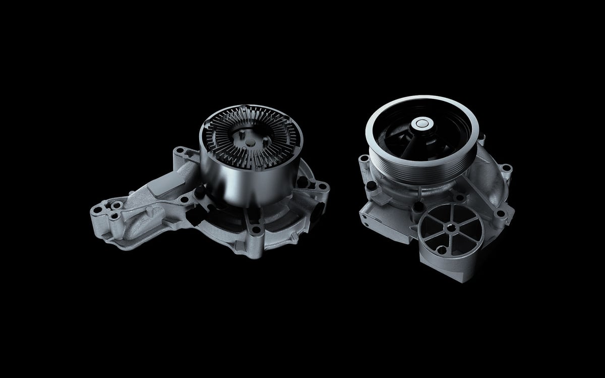
On a hot August afternoon, a loaded tractor unit eases onto the hard shoulder halfway up a long climb, the driver watching the temperature needle creep upward. The engine hasn't overheated yet — it is running just a notch above its usual band, and the air coming from the cab vents feels cooler than it should. On the phone, the fleet manager is ready to say "keep going, we'll get it into the workshop tonight." But that single notch on the gauge is often the first, and sometimes the only, gentle warning that circulation in the cooling circuit can no longer carry away the heat the engine is producing. This guide treats the water pump not as a part you unbolt and replace, but as the heart of the cooling circuit that keeps a heavy commercial vehicle working without interruption: where it sits in the circuit, how it is driven, how its flow relates to engine load, and why this component carries a far heavier operational responsibility in a truck than it does in a passenger car.
Why Cooling Load Is a Separate Engineering Challenge in Commercial Vehicles
A passenger car engine spends most of its day at partial load; it reaches full power only for seconds at a time, with plenty of opportunity to cool down in between. In a heavy commercial vehicle, the picture is reversed. A loaded tractor unit climbing a long grade produces a large share of its rated power continuously for minutes at a stretch, sometimes for a quarter of an hour without a break. Roughly a third of the fuel's chemical energy goes to the wheels; a similarly large share stays behind as heat in the engine block, and the cooling circuit has to remove that heat at the same rate it is produced.
The second difference is the auxiliary consumers on the circuit. In a commercial vehicle, coolant does not only pass through the engine block and cylinder head; the engine oil cooler, the EGR cooler, the cab heater, in most applications the air brake compressor's cylinder head, and on some vehicles the retarder cooler all draw from the same circuit. Every branch takes its share of the flow the pump is pushing. Unlike a passenger car, a heavy-duty water pump therefore has to feed an entire cluster of independently operating consumers at once, not a single heat source.
What Is a Water Pump? Its Role in the Cooling Circuit
A water pump is a centrifugal circulation pump, driven by the engine's own motion, that keeps coolant moving continuously around the closed cooling circuit through a vaned impeller. Its job is not to cool the coolant but to move it. The radiator is what cools the coolant; the thermostat is what governs its temperature; the pump simply keeps the fluid moving at sufficient speed and volume so that those two components can do their job. The moment circulation stops, neither the radiator nor the thermostat can do anything at all.
Several functions sit together inside a single housing. On the drive side there is a pulley or gear, the shaft it turns, the bearing assembly that carries the shaft, the vaned impeller that pushes the coolant, the volute-shaped housing the impeller spins inside, and — the single most critical part — the mechanical seal that keeps the shaft and the coolant apart. The small weep hole underneath the housing is not a fault but a design feature: the moment the seal starts to leak, it routes the coolant outward instead of into the bearing, giving the driver an early warning.
The working principle is simple, but its consequences are decisive. As the impeller turns, it flings the coolant at its centre outward toward the rim; the pressure that builds up at the rim pushes coolant out through the outlet and into the block's water jacket, and the coolant completing the circuit returns to the centre through the inlet. The pump's own pressure is not high in absolute terms — just enough to overcome the circuit's resistance and keep the flow continuous. That is why a water pump's performance is measured not by pressure but by the volume it moves per unit time, its flow rate.
Mapping the Cooling Circuit: From the Pump to the Heater Line, What Every Part Does
To understand the water pump's operational role, it helps to see the whole circuit as a single loop. It begins with coolant leaving the pump and passing through the engine block and cylinder head. As it heats up, it reaches the thermostat housing; while the thermostat is closed, coolant does not go to the radiator at all — it returns straight to the pump inlet through the bypass line, letting the engine reach operating temperature quickly. Once the thermostat opens, the flow is redirected to the radiator: coolant enters through the top hose, sheds its heat to the airflow moving through the core, and returns to the pump inlet through the bottom hose.
Alongside this main loop there are secondary branches. The heater line draws hot coolant from the cylinder head to warm the cab and returns it to the pump inlet, which makes cab heater performance a quiet indicator of how well the circuit is circulating. The expansion tank, meanwhile, is the circuit's pressure and volume manager: it absorbs the coolant's expanding volume as it heats up, gives that volume back as it cools, separates out any air that has entered the system, and, through the valve in its cap, keeps the circuit at a modest pressure above atmospheric, which raises the coolant's boiling point.
| Component | Task | Consequence of a fault for the pump and circulation |
|---|---|---|
| Water pump | Circulates coolant around the closed circuit | If flow drops, the whole circuit stops working and overheating follows |
| Thermostat | Chooses between the bypass line and the radiator branch | Stuck closed takes the radiator out of the circuit; stuck open, the engine never warms up |
| Radiator | Transfers the coolant's heat to the airflow | Blockage forces the pump to work harder; heat can't be shed even if flow stays the same |
| Expansion or degas tank | Absorbs the expanding volume, separates out air | An aerated circuit lets the impeller spin dry and cavitation begins |
| Pressure cap | Keeps the circuit pressurised, delays boiling | A weak cap causes flashing and cavitation on the inlet side |
| Heater line | Heats the cab, opens a second path in the circuit | Weak cab heating is an early sign of falling circulation |
| Engine oil cooler | Transfers heat from the oil to the coolant | An internal leak mixes oil and coolant and ruins the seal |
| EGR cooler | Cools exhaust gas before it returns to the intake | A crack lets combustion gas into the circuit and creates an air pocket |
| Fan and fan clutch | Draws air through the radiator | If it fails to engage, overheating follows at low speed and idle |
| Belt and tensioner | Transmits motion to the pump | Slip or breakage means the pump turns without delivering flow |
How this table should be read matters. None of these rows is, on its own, a diagnosis. Every fault in the circuit converges on the same shared symptom, the temperature gauge, because that is where weakened circulation ultimately shows up. An overheating complaint is therefore a recorded outcome, not the source. For a detailed breakdown of what actually drives a temperature rise, the guide to engine overheating in heavy-duty trucks is the natural next read.
How Is a Water Pump Driven? Belt, Gear and Camshaft Drives
The water pump takes its motion from the engine itself, and exactly how that motion reaches it shapes the part's whole maintenance behaviour. Three drive layouts run side by side across the heavy-duty fleet, and each carries a different operational consequence.
On a belt-driven pump, the impeller is turned by a multi-ribbed belt off the crank pulley. Access is easy and the cost is low; against that, belt tension, the tensioner bearing and the idler pulley all directly affect the pump's running condition. A belt pulled too tight loads the bearing sideways and shortens seal life, while a belt left too loose slips under high load and quietly cuts flow.
On a gear-driven pump, motion comes off the timing gear train. There is no slip risk, motion is positive, and service life is usually longer, but access sits mostly behind the front cover, which stretches out labour time and downtime. In camshaft- or auxiliary-shaft-driven designs, the pump is bolted straight into the engine's internal mechanism; in this layout a seal leak carries a higher risk of coolant meeting engine oil, which makes early intervention even more critical.
| Drive type | How it takes its motion | Operational strength | Maintenance and downtime outcome |
|---|---|---|---|
| Belt-driven (pulley) | Multi-ribbed belt off the crank pulley | Easy access, short labour time, can be checked by eye | Assessed together with the belt, tensioner and idler; tension decides service life |
| Gear-driven | Off the timing gear train | No slip, positive motion, flow tracks engine speed exactly | Access sits behind the front cover; intervention has to go into a planned stop |
| Camshaft or auxiliary-shaft driven | Off the engine's internal shaft arrangement | Compact packaging, less load on the belt line | Higher risk of coolant meeting oil on a leak; early action is essential |
| Separate-pulley dual-circuit layout | Main circuit and auxiliary circuit fed separately | Auxiliary coolers run independently of the main circuit | Both circuits need their level and leaks tracked separately |
Knowing the drive type is not just a technical detail, it is a planning decision. On a belt-driven engine, a pump replacement is a job of a few hours; on a gear-driven engine, the same job takes considerably longer and can take the vehicle off the road for the better part of a day. A fleet maintenance calendar cannot treat those two cases as the same line item.
Flow, Engine Speed and Load: When the Pump Is Pushing Hardest
A centrifugal pump's flow rises with impeller speed: the faster the engine turns, the more coolant the pump pushes; the slower it turns, the less flow there is. This simple relationship produces three important consequences in heavy commercial vehicles, and most of the behaviour seen in the field traces back to them.
First, high load at low engine speed is the most demanding combination there is. A heavily loaded vehicle climbing in a low gear is exactly the moment when heat generation is near its ceiling while pump flow is relatively low. The same vehicle can run for hours at high revs on flat, empty roads without a single symptom, then push the temperature gauge upward that same day on a single climb. A weakened pump reveals itself right here first, hidden on the flat and exposed on the grade.
Second, idle is not the safe zone it is often assumed to be. A vehicle sitting at idle for long periods has both low pump flow and no ram air moving through the radiator; the whole circuit depends on the fan clutch engaging at exactly the right moment. This is why fleets with long idling habits tend to see cooling complaints show up during standing time rather than out on the road.
Third, the gain in flow at high engine speed has a ceiling of its own. If inlet-side pressure is not sufficient, a local pressure drop at the impeller eye causes some of the coolant to flash into vapour. The resulting bubbles collapse in the higher-pressure zone downstream and hammer the metal surface. This phenomenon, cavitation, both cuts flow and slowly erodes the impeller vanes and housing. A weak pressure cap, a low coolant level, an aerated circuit and the wrong mix ratio are the leading triggers of cavitation.
Why the Water Pump Is More Critical in Commercial Vehicles Than in Passenger Cars
Technically, the water pump in a passenger car and the one in a heavy commercial vehicle obey the same laws of physics. Operationally they are two different worlds, and the difference comes not from the part itself but from what its failure sets off.
The first difference is exposure time. A passenger car doing fifteen thousand kilometres a year accumulates in a full year what a tractor unit covering hundreds of kilometres a day puts its pump through in just a few weeks. The second difference is the severity of the duty cycle: sustained high load, long climbs, high ambient temperature and dusty construction-site conditions all directly shorten bearing and seal life.
The third, and most expensive, difference is secondary-damage risk. In a passenger car, an early-noticed temperature rise is usually managed by simply pulling over. In a loaded commercial vehicle running at high load, once temperature runs out of control the result can be a warped cylinder head, a blown gasket, and in more severe cases a rebuilt engine. There is an order-of-magnitude gap between what a water pump costs as a part and what neglecting it can cost in repairs.
The fourth difference is downtime itself. A tractor unit stranded on the road does not just produce a repair invoice: the cost of a tow, disrupted driver hours-of-service, a missed delivery window, a blown appointment at the consignee, and, for some loads, a broken cold chain all land at once. In most fleets, the sum of these cost lines runs many times higher than the parts and labour combined.
Further reading
For a plain-language technical overview of this subject, see the reference article on Wikipedia. Always confirm specific figures and procedures against the vehicle manufacturer service data.
Early Warning Signs and What Fleet Tracking Should Watch For
A water pump rarely dies suddenly. There is almost always a weeks-, sometimes months-long weakening period beforehand, and the signs it gives off during that time tend to get written off as ordinary. The real gain for a fleet operation comes from building an observation discipline that catches these signs before they turn into a breakdown.
| Sign | What it indicates | First check |
|---|---|---|
| Moisture, sediment trace or drip at the weep hole | The mechanical seal has started leaking | Clean the housing and recheck it cold and hot |
| Level falling with no visible leak | Fluid evaporating out or leaking into another circuit | Run a pressure test, check the exhaust and oil sides |
| Play or wobble felt by hand at the pulley | The bearing assembly has worn out | Loosen the belt and check the shaft for radial and axial play |
| Constant whine or whistle from the engine bay | The bearing is noisy or the belt is slipping | Isolate the noise source, assess the belt line separately |
| Temperature above the usual band under load | Flow has dropped, heat is not being shed fast enough | Take a comparative temperature reading on the same route |
| Overheating tendency at idle or low speed | Fan clutch fault or low-speed flow problem | Watch the fan engagement and thermostat behaviour |
| Constant bubbling in the expansion tank | Combustion gas leak or air on the inlet side | Run a combustion-gas test, check the cap and level |
| Dust, glazing or edge wear on the belt | Slip, misalignment or wrong tension | Check tensioner force and pulley alignment |
None of these signs is conclusive on its own; their value lies in the trend over time. If a vehicle needs half a litre of top-up once a month, that is not an event, but if the same vehicle starts asking for it once a week, there is a progressing loss somewhere in the circuit. The removal, measurement, replacement and post-installation verification steps are a separate subject in their own right; for the part's own diagnosis and step-by-step replacement, see the water pump faults, replacement and maintenance guide. This section's scope is when, and on what operational grounds, that intervention should be planned.
Evaluating the Water Pump Alongside Its Neighbouring Parts
The most expensive mistake repeated in the field is replacing the pump on a vehicle that arrives with an overheating complaint and expecting the problem to be solved. The water pump is not a component that operates alone; it forms one link in a circle with three neighbouring groups: the drive train, temperature management, and airflow.
The drive train is made up of the belt, tensioner bearing, idler pulley and pulley. A fault in any member of this group makes the pump itself look guilty. A loose belt slips under high load and cuts flow; excessive tension, on the other hand, loads the pump bearing sideways continuously and shortens its life. A misaligned pulley chews the edge of the belt while also applying an angled load to the shaft. Skipping a review of this whole group at pump replacement time is how a new part ends up living out the old part's shortened life.
On the temperature management side, the thermostat plays the lead role. A thermostat stuck closed takes the radiator out of the circuit entirely, and the engine overheats even if the pump is running at full capacity; one stuck open, on the other hand, keeps the engine from reaching operating temperature, raising fuel consumption and soot build-up. Renewing the thermostat at the same time as the pump removes a second downtime before it happens, which makes it almost always the right operational call.
On the airflow side sit the radiator core, the fan, the fan clutch and the air-directing shrouds. A core clogged with insects, dust and oil film cannot shed heat outward, no matter how flawless the circulation inside the circuit is. A missing or cracked shroud lets the air the fan is pulling bypass the radiator core, a fault that is easy to miss in the field and costs almost nothing to fix.
How Coolant Quality Affects Water Pump Life: Cavitation, Corrosion and Electrolysis
The single strongest factor determining a water pump's service life is the chemical condition of the fluid running through it. The mechanical seal and the impeller are two surfaces that spin thousands of times a day and stay in the fluid continuously; what protects those surfaces is the fluid's additive package. Once the additives are exhausted, the pump is left chemically unprotected.
Corrosion comes first. Aluminium, cast iron, copper, brass and steel all sit in the same circuit, and different metals in contact through the same fluid produce a galvanic effect. The additive package suppresses that effect. Once it is exhausted, the oxide and sediment that build up act like sandpaper on the seal's sliding face, and leaks begin. Scale and sediment come second: top-ups made with tap water or mineral-heavy water leave deposits in the circuit that both reduce heat transfer and choke flow through narrow passages.
Cavitation is specific to the pump and the most insidious of the three. When local pressure drops on the inlet side, the vapour bubbles that form collapse in the higher-pressure zone and strike the metal surface with a great many tiny impacts. Over time the impeller vanes are eroded, the housing's inner surface roughens, and flow drops permanently. The right mix ratio, a full circuit free of trapped air, and a sound pressure cap are the three most effective safeguards against cavitation.
Electrolysis is less well known but a real risk in heavy commercial vehicles. When equipment added to the chassis afterward is not properly earthed, stray current takes the easiest path available, and that path sometimes runs through the coolant. The result is accelerated wear on metal surfaces. Where a pump or radiator keeps wearing out for no obvious reason, the earth connections of the electrical installation should be checked as well.
Mix ratio, additive type, the gelling risk that comes from mixing different coolant types, and change intervals are a subject in their own right; for coolant selection and change timing, the guide to antifreeze and coolant types and when to change them lays out a detailed framework. The rule that matters for a fleet is simple: record which type is used in which vehicle, top up with the same type, and only change type after a full drain and flush.
Pre-Trip and Periodic Cooling System Checklist
The list below is arranged so a driver can work through the cooling circuit quickly but thoroughly during a pre-trip walk-around, and a workshop can do the same at periodic service. Every step is carried out with the engine cold and the vehicle safely secured.
- Park the vehicle on level ground, apply the parking brake, switch off the ignition and let the engine cool completely; before opening the bonnet, check by eye for escaping steam or hot surfaces.
- Compare the level in the expansion tank against the cold mark and read it alongside the previous record; what matters is not the level at this one moment but how it is trending over time.
- Check the colour and clarity of the fluid: cloudiness, an oil film, rust-coloured sediment or foam on the surface all point to an exhausted additive package or a foreign substance entering the circuit.
- Inspect the pressure cap's gasket and sealing face; a hardened, cracked or scale-caked gasket cannot hold the circuit's pressure and increases the risk of cavitation on the inlet side.
- Clean the weep hole under the water pump housing and look for a trace; dried sediment is just as meaningful as a fresh drip and points to an intermittent leak.
- Grip the pump pulley by hand and check for radial and axial play, then loosen the belt and turn the pulley by hand, listening for whether the bearing spins smoothly.
- Examine the belt end to end: look for cracking on the back, edge wear, glazing, a filled-in rib or a torn rib, and confirm the pulleys are aligned and the tensioner moves freely.
- Squeeze the top and bottom radiator hoses and the heater hoses by hand to check for hardening, sponginess or internal collapse; look for a permanent crease or damp trace around the clamps.
- Hold a light up to the front face of the radiator and any charge-air cooler core and check for insects, dust, leaves and oil-film blockage; confirm the air-directing shrouds are complete and intact.
- Start the engine and bring it up to operating temperature; watch the top hose warm up as the thermostat opens, then watch the fan engage and disengage, and note the gauge's behaviour.
- If in doubt, pressure-test the circuit with the appropriate equipment, and run a combustion-gas test if needed; log the result of both tests against the date in the vehicle file.
- Log every observation made, along with the top-up quantity and the fluid type used; this record is the only basis for reading the trend at the next service.
The value of this list is not in running it once, it is in repeating it on the same vehicle and comparing the results. A level reading taken at a single service is one data point; a level that falls at three services in a row is a diagnosis.
The Water Pump in a Fleet Maintenance Plan: Records, Trends and Planned Intervention
The water pump has no fixed change interval defined by distance; its life depends far more on duty cycle, coolant condition and drive-train maintenance than on kilometres covered. That uncertainty is exactly why a fleet has to manage the part by trend tracking rather than by a calendar.
Trend tracking rests on three records. The first is the top-up log: the date and quantity of every level top-up gets written down. The second is the temperature log: in fleets with telematics, the peak temperature recorded on the same route under the same load, tracked over months, reveals a deviation long before any warning light comes on. The third is the fluid condition log: mix ratio and additive condition are checked periodically with a test strip or the appropriate meter, and the result goes into the file.
Reading these three records together gives the fleet manager the ability to move a part replacement into a planned stop. A planned stop can be timed to a date the vehicle is already going to be in the workshop for something else; a roadside breakdown sets its own timetable and dictates its cost to the operation.
Downtime Cost and the Planned-Replacement Decision
Deciding on a water pump replacement by parts cost alone is a calculation that misleads a commercial fleet. The correct comparison is not parts versus labour, it is planned downtime versus unplanned downtime. The gap between the two runs, in most fleets, to several multiples of the part's own cost.
| Comparison heading | Planned downtime | Unplanned downtime after a breakdown |
|---|---|---|
| Timing | Chosen to fit the workshop and trip schedule | The failure dictates the moment; there is no choice |
| Parts supply | The correct reference is sourced in advance | Pressure to make do with whatever part is available |
| Scope | Thermostat, belt, tensioner and hoses handled together | Only the minimum work needed to get the vehicle moving again |
| Secondary damage | Risk stays low because temperature never nears the limit | Risk of a warped head and blown gasket comes into play |
| Driver and load | The trip plan stays intact | Hours-of-service is disrupted, delivery slips, the load is put at risk |
| Extra cost lines | Labour is shared across one planned stop | Towing, delay and a second repair all get added on |
| Predictability | Can be written into the budget ahead of time | An unplanned line item the budget cannot anticipate |
The decision rule can be summarised plainly: if at least one early warning sign is recorded and repeating, if the vehicle's remaining trip profile is demanding, and if the drive type means labour will run long, the intervention belongs in a planned stop. That threshold should be pulled forward even further ahead of the summer heat and long-haul, fully loaded periods.
Common Field Management Mistakes and the Right Call
Most mistakes around the cooling circuit do not come from a lack of knowledge, they come from a preference for whatever is easiest in the moment. Here are the most common ones and the right call in each case.
- Topping up with tap water: This keeps the vehicle moving in an emergency, but it leaves scale and minerals in the circuit and dilutes the additive package. The right call is to correct it with the proper mix at the first opportunity and log what happened.
- Mixing different coolant types: When the additive chemistries are incompatible, gelling and sediment form and narrow passages choke up. The right call is to keep a record of which type is used in the vehicle and only change type after a full drain and flush.
- Wiping away the trace at the weep hole and moving on: This hole exists to warn you. The right call is to clean the trace, check back at regular intervals, and log a trace that keeps reappearing.
- Over-tensioning the belt: Over-tightened out of fear of slipping, a belt like this loads the pump bearing sideways continuously and shortens its life. The right call is to follow the OE value, or the tensioner's indicator if the vehicle has an automatic tensioner.
- Sealing a leak with a stop-leak additive: A quick fix like this clogs the circuit's narrow passages and the radiator core, and makes the underlying problem worse. The right call is to find the source of the leak and fix it.
- Replacing only the pump and leaving the thermostat alone: Renewing one of two parts that share the same age and the same load produces a second downtime in short order. The right call is to evaluate both together in the same stop.
What all of these have in common is that none of them requires advanced technical knowledge. Every one is a matter of maintenance procedure and record-keeping habit, which means fixing them takes discipline, not investment.
General Reference Figures and Orders of Magnitude
The table below gives a sense of scale for weighing whether a measured result in the cooling circuit is reasonable. None of the values in it replace the service documentation for the vehicle's engine code.
| Quantity | General reference or benchmark | Interpretation |
|---|---|---|
| Engine operating temperature band | A narrow band set by the thermostat's opening temperature | What matters is not the absolute figure but a deviation from the vehicle's own normal |
| Circuit pressure | Modestly above atmospheric, limited by the cap | Pressure delays boiling and reduces cavitation risk on the inlet side |
| Coolant mix ratio | The water-to-concentrate ratio the manufacturer specifies | Over-concentrated reduces heat transfer, over-diluted with water reduces protection |
| Pump flow rate | Directly proportional to engine speed, absolute value is OE data | Low speed with high load is the most demanding combination |
| Pulley and shaft play | Play felt by hand is not acceptable | Felt play is a firm sign of bearing fatigue |
| Weep hole discharge | Persistent moisture, sediment trace or drip is not acceptable | The seal has begun to reach the end of its life |
| Belt tension | OE value or an automatic tensioner's indicator | Over-tension wears the bearing, slack cuts flow |
| Water pump change interval | No fixed interval; condition and trend decide | Duty cycle and fluid quality directly change service life |
The table's real rule is this: no numerical value in the cooling circuit can be used independently of the engine code and equipment level. Two engines of the same displacement from the same manufacturer can call for very different values because of a different emissions level, a different fan layout or different auxiliary cooler equipment.
The Water Pump Is the Cooling System's Health Mirror
The water pump is a small, relatively inexpensive part in a heavy commercial vehicle, but where it sits makes it the system's health mirror. Every fault in the circuit sooner or later becomes visible through it: exhausted additive eats the seal, an aerated circuit erodes the impeller, an over-tight belt wears out the bearing, a clogged core makes the pump look guilty. That is why a pump failure is, more often than not, not a parts failure at all but the mark maintenance discipline leaves behind. That is the real answer, on the ground, to the question of what a water pump is in a commercial vehicle: as much about the maintenance regime around the part as about the part itself.
For a fleet, the takeaway is simple. A water pump is managed by record, not by a mileage chart. When top-up quantity, peak temperature under load, fluid condition and weep-hole observations are logged consistently, the part almost never delivers a surprise; when those records are not kept, the same part will remind you of its existence on the heaviest climb, at the least convenient hour. In every case, the current OE service documentation for the vehicle's engine and chassis code is authoritative, and every decision in the field should be checked against it.
Shop this part: Water Pump
Main guide: Water Pump: Faults, Replacement & Maintenance Guide
Tags
Frequently Asked Questions
- What is a water pump in commercial vehicles, and what does it do?
- A water pump is a centrifugal circulation pump, driven by the engine's own motion, that keeps coolant moving continuously around the closed cooling circuit through a vaned impeller. Its job is not to cool the coolant but to move it: the radiator is what cools it, the thermostat governs its temperature, and the pump simply keeps the fluid moving at sufficient flow so those two components can do their work. The moment circulation stops, neither the radiator nor the thermostat can do anything at all, which is why the pump is the most critical link in a heavy commercial vehicle's cooling circuit.
- Is a water pump the same thing as a coolant pump?
- Yes, both terms describe the same part. "Water pump" is the standard name used across workshops, parts catalogues and OE documentation; "coolant pump" is simply a more literal name for the same component, since the fluid it circulates is properly called coolant rather than plain water. Whichever name is used on a given invoice or manual, it refers to the same centrifugal pump that drives circulation through the engine block, radiator and heater circuit.
- Where does the water pump sit in the cooling circuit, and what parts does it work with?
- The pump sits on the discharge side of the circuit: it pushes coolant into the water jacket around the engine block and cylinder head, and the coolant completing its loop returns through the pump's inlet. It works directly alongside the thermostat, radiator, expansion or degas tank, pressure cap and heater line. In a heavy commercial vehicle these are joined by the engine oil cooler, the EGR cooler, in most applications the air brake compressor's cylinder head, and on some vehicles the retarder cooler; every branch on the circuit takes its share of the flow the pump is pushing.
- How is a water pump driven in a heavy commercial vehicle?
- Three layouts are common. In a belt-driven pump, the impeller is turned by a multi-ribbed belt off the crank pulley; access is easy, but belt tension, the tensioner bearing and pulley alignment directly affect the pump's condition. In a gear-driven pump, motion comes off the timing gear train; there is no slip risk, but access usually sits behind the front cover, which stretches out labour time. In camshaft- or auxiliary-shaft-driven designs, the pump is bolted straight into the engine's internal mechanism, so a seal leak carries a higher risk of coolant meeting engine oil.
- What are the earliest signs of water pump failure?
- The earliest signs are usually the ones that get written off as ordinary: moisture, sediment or a drip at the weep hole underneath the housing, a level that falls slowly with no visible leak, play or wobble felt by hand at the pulley, a constant whine from the engine bay, weaker cab heating, and temperature climbing above the vehicle's usual band under load. None of these signs is conclusive on its own; their value comes from tracking the same vehicle over time and logging when they start repeating.
- Is it normal for coolant to appear at the water pump's weep hole?
- The hole itself is normal, a drip from it is not. The small weep hole under the pump housing is a deliberate design feature: when the mechanical seal starts to leak, it routes the coolant outward instead of into the bearing, giving an early warning instead of a silent failure. Persistent moisture, a dried sediment trace or an actual drip at that hole means the seal has begun to reach the end of its life, and the intervention should be moved into a planned stop.
- Can a truck keep running with a failing water pump?
- It should not. Once circulation weakens, temperature in a loaded commercial vehicle running at high load can run out of control in a very short time, and the result can be a warped cylinder head and a blown gasket. The cost of that secondary damage runs to several multiples of the pump's own price. If the gauge climbs above its usual band, the right response is to pull over safely, let the engine cool without opening the cap, and have the vehicle towed rather than pushing on.
- How many kilometres does a water pump last?
- There is no fixed distance-based change interval; service life depends far more on duty cycle, coolant condition and drive-train maintenance than on kilometres covered. A pump on a vehicle doing long, fully loaded hauls in hot conditions will not last as long as one on a lightly loaded local-delivery truck. That is why the part should be managed through trend tracking rather than a mileage chart: top-up records, peak temperature under load, and fluid-condition checks. For an exact figure, the current OE service manual for the vehicle's engine and chassis code is authoritative.
- Should the thermostat and belt be replaced along with the water pump?
- In almost every case, yes. The thermostat, belt, tensioner bearing and idler pulley share the same age and the same load as the pump, and renewing only one of them tends to produce a second downtime shortly afterward. Handling the whole group in a single planned stop, alongside a check of the radiator core and air-directing shrouds, is both cheaper and far more predictable on the schedule than three separate workshop visits for parts that were due at the same time.
- How does coolant quality affect water pump life?
- Directly and decisively. Once the additive package is exhausted, the different metals in the circuit corrode against each other, and the resulting oxide and sediment act like sandpaper on the seal's sliding face. Topping up with tap water leaves scale and mineral deposits that choke narrow passages. An aerated circuit or a weak pressure cap triggers cavitation, which erodes the impeller vanes and permanently reduces flow. Keeping the mix ratio correct, topping up with the same coolant type, and only changing type after a full drain and flush are the most effective ways to protect the pump.
Related Articles
Truck Water Pump Repair: Housing, Gasket and Water Pipe
Learn how a heavy truck water pump fails, how to diagnose leaks and bearing noise, and how to replace the housing, gasket and water pipe correctly.
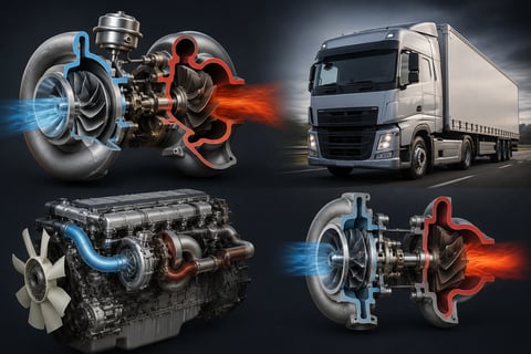
What Is a Turbocharger? Turbo Failure Symptoms in Diesel and Heavy-Duty Vehicles
What is a turbocharger and how does it work? Turbo failure symptoms, VGT vane sticking, and the oil habits that determine service life in heavy-duty diesels.
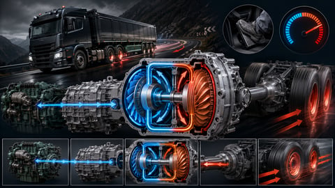
What Is a Retarder? How Does It Work and What Does It Do?
What is a retarder, and how does it work? Hydraulic vs electromagnetic retarders, stages, engine-brake differences, faults and maintenance for heavy trucks.


