Transmission PTO: Faults, Replacement and Maintenance Guide
A workshop guide to truck transmission PTO units: how they work, why they fail to engage, correct backlash setting on fitting and habits that extend life.
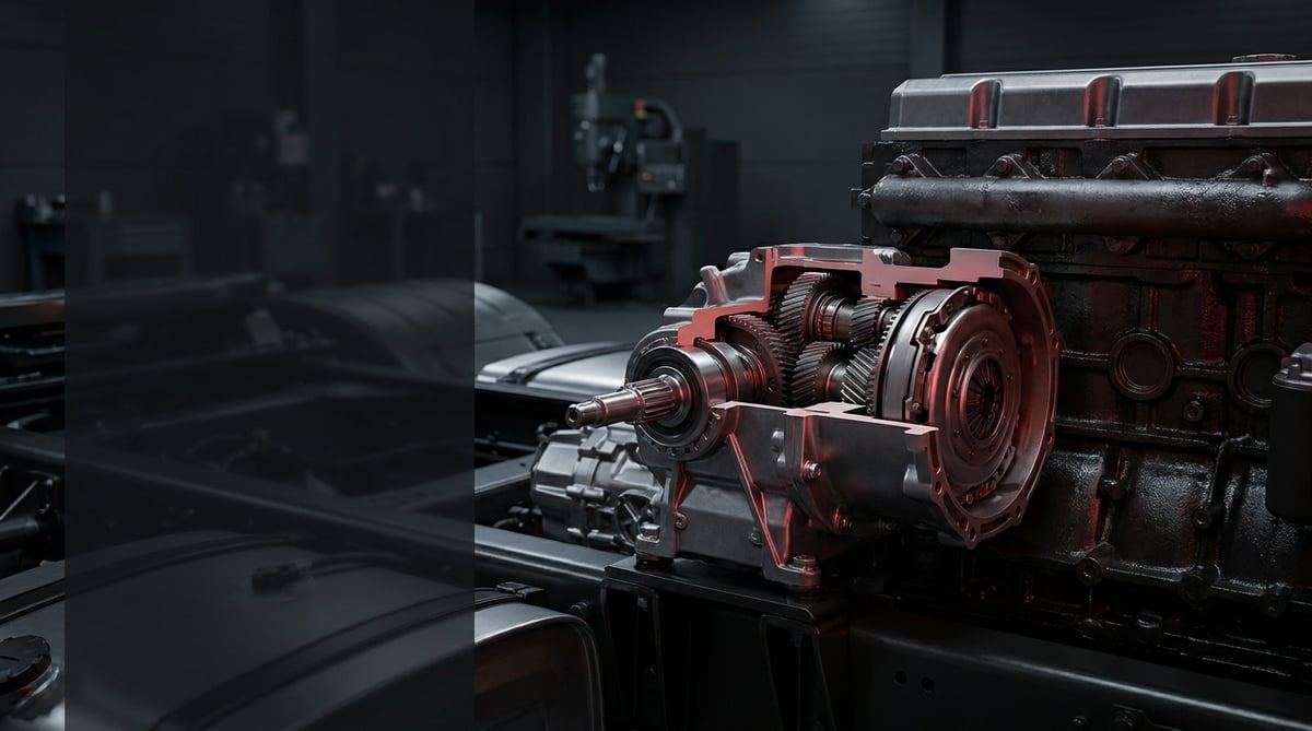
A tipper that will not raise its body, a concrete mixer stranded halfway through a job or a recovery truck whose crane arm refuses to deploy usually point to the same place: the small gearbox bolted to the side cover of the transmission. Known in the workshop as the power take-off unit, the drive take-off or simply the PTO, this component is the only bridge carrying engine power to the bodywork equipment, and when it fails the vehicle still drives but cannot do any work. Written from the point of view of a workshop foreman and service technician, this guide explains what a transmission PTO does, how it fails, the correct diagnostic sequence, the discipline required during fitting and the maintenance habits that extend its service life.
What Is a Transmission PTO? Function and Operating Principle
A transmission PTO (Power Take-Off, power take-off unit) is a gear unit bolted to the side or the rear of the transmission housing that takes its drive from the countershaft gear and transfers part of the engine power to bodywork equipment such as a hydraulic pump, tipper, mixer, crane or compressor. In heavy commercial applications the output speed is typically in the range of 50 to 140 percent of engine speed, while continuous torque capacity is in the order of 300-1,200 Nm depending on the model.
The transmission PTO goes by several names both in the workshop and in the catalogue: power take-off unit, drive take-off, PTO box or simply power take-off. Whichever name it is searched under, the selection criteria are the same: transmission type, output flange pattern and the required speed ratio.
The operating principle is built on a simple gear engagement. When the side cover of the transmission is removed, a gear on the countershaft becomes visible underneath. The PTO unit seats into this opening and its own input gear remains in permanent mesh with the countershaft gear. When the driver operates the switch in the cab, pressure from the vehicle air system is routed through a solenoid valve to the pneumatic piston inside the PTO; the piston pushes the sliding gear or the coupling sleeve towards the output shaft and the drive chain is completed. The flange on the output shaft then starts to turn the propshaft or the directly mounted hydraulic pump.
The critical point that is often overlooked is this: a classic side mount PTO takes its drive from the countershaft, and the countershaft turns at engine speed whenever the clutch is not depressed. That is why engagement is carried out with the engine running and the vehicle stationary. Clutch independent sandwich type units and split-shaft types mounted behind the transmission, on the other hand, are designed to transmit power while the vehicle is moving; these are common on mixers and road sweepers.
Which transmission families does it appear on?
What determines the compatibility of a transmission PTO is not the make of the vehicle but the transmission family and the cover pattern it is fitted to. On the heavy commercial side the most frequently encountered applications are the ZF Ecosplit and TraXon families, Mercedes-Benz G and GO series transmissions, Volvo I-Shift, Scania GRS/GRSO and gearboxes of Eaton origin. Different production years of the same tractor unit may use different cover patterns, so a PTO should never be ordered without first reading the type code on the transmission plate. The side cover interface is largely standardised across the industry: six and eight bolt hole patterns and output shaft spline profiles correspond to ISO 7653 (transmission power take-off flange dimensions) and the DIN 5462 / ISO 14 straight sided spline standards, while on the hydraulic pump side the SAE J744 mounting interface is widespread. Since the applicable standard may vary by manufacturer and model, exact data must be verified from the OE catalogue for the part concerned.
Components and ancillary elements
- Housing: aluminium or cast iron, the main body that carries the gears and bolts to the transmission.
- Input gear: the element that meshes with the countershaft gear, its backlash being set during fitting.
- Sliding gear or coupling sleeve: the part that carries out the engagement and disengagement movement.
- Pneumatic cylinder and piston: the actuator that pushes the sleeve with air pressure.
- Solenoid valve and air line: the circuit that converts the signal from the cab switch into pressure.
- Feedback switch: the sensor that illuminates the indicator lamp and confirms engagement.
- Output shaft and flange: the power outlet connected to the propshaft or the pump.
- Bearings, seals and gasket pack: the consumable group that determines service life and sealing.
How do PTO types differ?
The speed, torque and duty cycle demanded by the application determine which type is selected. Short duty, high torque tipper work and mixer work that runs for hours on end cannot be covered by the same unit.
| PTO type | Mounting position | Typical speed ratio | Common application |
|---|---|---|---|
| Side mount, clutch dependent | Transmission side cover, 6 or 8 bolt | 50-110 percent of engine speed | Tipper, hooklift, hydraulic lifting |
| Side mount high performance | Transmission side cover, reinforced housing | 90-140 percent of engine speed | Crane, compaction refuse body, high flow pump |
| Rear mount | Transmission rear cover | 80-110 percent of engine speed | Concrete pump, special bodywork |
| Sandwich type (clutch independent) | Between engine and transmission | Directly related to engine speed | Mixer, sweeper, operation while driving |
| Split-shaft (in-line) | On the propshaft line | Varies with the application | Fire pump, high power stationary duty |
How do you identify a transmission PTO failure?
Transmission PTO failures generally fall under three headings: failure to engage, failure to disengage, and mechanical noise with leakage. The first is mostly pneumatic or electrical, the third mechanical. The table below matches the symptoms most frequently met in the field with their likely causes and the way to verify them.
| Symptom | Likely cause | Check / verification |
|---|---|---|
| Cab switch is operated, the PTO does not engage at all, the indicator does not light | No air or no electrical supply reaching the solenoid valve; fuse, switch or line fault | Pressure measurement with a gauge at the solenoid outlet; check of the supply voltage with a multimeter; test of the fuse and cab switch |
| The indicator lights but the output shaft does not turn | The feedback switch is reporting a false position or the sliding gear has not fully engaged | Comparing the switch signal with actual rotation of the output shaft; verifying that air pressure is within the working range |
| Metallic grinding, crunching noise during engagement | Engaging before the clutch is fully depressed; engaging at high engine speed; worn sliding gear teeth | Repeating the engagement procedure at idle speed; removing the cover and checking the gear tooth ends for rounding and peening |
| Continuous whine in operation, noise rising with speed | Backlash set incorrectly, bearing fatigued or oil level dropped | Check of transmission oil level and colour; backlash measurement with a dial gauge; locating the noise source with a stethoscope |
| Oil leaking between the PTO housing and the transmission | Gasket pack crushed, bolt torque lost or the mating face scored | Leak tracing on a cleaned surface; rechecking bolt torques with a torque wrench |
| Oil dripping from behind the output shaft flange | Output seal hardened; propshaft angle incorrect, shaft running out | Visual inspection of the seal lip; measuring flange run-out with a dial gauge |
| The PTO does not disengage, it keeps turning after the switch is closed | Air is not being exhausted, the piston has seized or the sliding gear is jammed in its seat | Listening for exhaust at the vent port; disconnecting the line and observing whether the piston moves freely |
| The unit overheats, the paint blisters | The continuous duty limit is exceeded, lubrication is insufficient or the unit is overloaded | Measuring surface temperature after operation with a non-contact thermometer; comparing bodywork running time against the records |
Rule out the pneumatic circuit first
The quickest gain in diagnosis comes from eliminating the air circuit before looking for a mechanical fault. A pressure gauge is connected to the solenoid valve outlet, the switch is operated and it is checked whether pressure reaches the working range. If pressure is present, the problem is inside the unit; if it is not, attention turns to the switch, the fuse, the solenoid or the air line. It is no exaggeration to say that frozen moisture or a blocked air filter is the most common finding in the field; this check takes five minutes and prevents unnecessary removal work.
Mechanical verification by speed measurement
Measuring the actual speed of the output shaft with an optical or inductive tachometer shows both that engagement is complete and that the correct ratio unit is in use. When engine speed and output speed are compared, a figure clearly below the catalogue ratio means the coupling is not fully seated. This measurement also reveals whether the bodywork pump is running at the wrong speed.
Oil and swarf inspection
The level, colour and metal content of the transmission oil are the most honest indicators in PTO diagnosis. While fine metal dust on the magnetic plug is considered normal, bright flake shaped swarf points to gear damage. A low oil level means the input gear has been running without lubrication and can on its own be the cause of a whine.
On automated gearboxes the same air supply also drives the shift actuators; to rule out a shared supply fault, read the guide on AMT gearboxes and shifting cylinder gear shift failures.
Further reading
For a plain-language technical overview of this subject, see the reference article on Wikipedia. Always confirm specific figures and procedures against the vehicle manufacturer service data.
How is a transmission PTO replaced? Step by step
Transmission PTO replacement is a half day job for an average workshop when it is carried out in the correct order; when the order is disturbed it creates secondary problems such as loss of transmission oil and incorrectly set backlash.
- Preparation and documentation: Note the type code on the transmission plate, the OE number on the old PTO and the speed ratio. Photograph the air and electrical connections before disconnecting them; this is the step that saves the most time during reassembly.
- Making the vehicle safe: Switch off the ignition, disconnect the battery terminal, drain the air reservoir, lower the bodywork and chock the wheels.
- Removing the propshaft or the pump: Mark and remove the propshaft attached to the output flange. On a directly mounted hydraulic pump, prepare a support to carry the pump; leaving the pump hanging on the shaft under its own weight causes shaft and seal damage.
- Disconnecting the pneumatic and electrical connections: Label and disconnect the air line and the feedback switch connector. Cap the open line ends against contamination.
- Managing the oil level: If the PTO aperture is not above the oil level, drain the transmission oil into a suitable container. Depending on how the vehicle is standing, partial draining may be sufficient; the level datum in the service manual decides.
- Removing the unit: Slacken the bolts in a crosswise sequence and in stages. Do not try to pull the unit off directly; separate the housing with a slight rocking motion without damaging the mating face. Support its weight as you lift it away.
- Checking the face and the gear: Clean the old gasket residue from the transmission cover face without using a metal scraper. Inspect the tooth flanks of the countershaft gear for peening, pitting and broken teeth; if there is damage, replacing the PTO alone is not a solution.
- Positioning the new unit: Fit the new transmission PTO in place with the gasket pack supplied by the manufacturer. Do not use liquid sealant in place of the gasket; here the gasket thickness is also the adjusting element.
- Setting the backlash: Measure the clearance between the input gear and the countershaft gear with a dial gauge or by the lead wire method. If the measured value is outside the band specified by the manufacturer, adjust it by adding or removing gaskets. When this step is skipped, the unit either whines within a short time or the teeth are overloaded and break.
- Torquing the bolts: Tighten the bolts in a crosswise sequence, in stages and with a torque wrench to the value specified by the manufacturer. Keep the use of countersunk fasteners and washers as per the original.
- Connections, oil and test: Refit the air line, the connector and the propshaft; top the transmission oil up to level. Run the engine at idle, engage and disengage the PTO several times, listen to the noise and check for leaks. Then run the bodywork first unloaded and then loaded, measure the speed and check the housing temperature after a short period of operation.
What are the most common mistakes in transmission PTO replacement?
Transmission PTO replacements that fail early do so mostly because of fitting discipline rather than the part itself. The headings below are the causes most frequently found in the field on units that come back to the workshop for a second time.
- Selecting a unit with the wrong speed ratio: A PTO bought without calculating the speed the bodywork pump demands either delivers insufficient flow or overspeeds the pump and burns it out in a short time.
- Tightening the bolts by hand or with an impact wrench: Without a torque wrench the face pressure remains uneven; the unit either leaks or the housing cracks.
- Engaging before the clutch is fully depressed: This is the real cause of rounded gear tooth ends and of that characteristic crunching noise.
- Engaging while the vehicle is moving: On clutch dependent types this operating error ends in gear breakage. Operation while driving is valid only on types designed for that duty.
- Handing the vehicle over without checking the transmission oil level: If the oil lost during removal is not made up, the new unit runs dry.
- Ignoring the propshaft angle and the pump weight: An unsupported pump and an incorrect angle destroy the output shaft and the seal in a short time.
- Taking the air supply from the brake circuit: Auxiliary consumers must be fed from their own protected circuit; anything else directly endangers braking safety.
- Reusing the old gasket, seal and single use items: These parts do their job by being crushed during assembly and will not give the same sealing a second time.
Transmission PTO technical values and inspection points
Transmission PTO technical values vary across a wide band depending on the model, the housing material and the application class. The tables below summarise the typical ranges met in the field in heavy commercial applications; the exact value must always be taken from the service documentation for the unit and the vehicle.
| Parameter | Typical range | Unit | Note |
|---|---|---|---|
| Engagement air pressure | 6.0-8.0 | bar | Vehicle system pressure is generally in the 8-12.5 bar range |
| Output speed (ratio to engine speed) | 50-140 | percent | Selected to suit the application; pump speed is the deciding factor |
| Continuous torque capacity | 300-1,200 | Nm | Varies by model according to housing and gear class |
| Momentary peak torque | 1.2-1.5 times the continuous value | Nm | Short duty only, not valid under repeated loading |
| Input gear backlash | 0.10-0.35 | mm | Set with the gasket pack; measured with a dial gauge |
| Transmission oil operating temperature | 80-100 | °C | Continuous operation above 120 °C shortens oil life |
| PTO housing surface temperature (under load) | 70-95 | °C | A clearly higher value is a sign of overloading |
| Hydraulic pump working pressure (tipper application) | 150-250 | bar | The value given by the bodybuilder takes precedence |
| Oil change interval (transmission) | 120,000-240,000 | km | The lower limit is approached with heavy PTO use |
| Joint | Typical bolt size | Torque band (Nm) |
|---|---|---|
| PTO housing to transmission cover | M10, class 8.8 | 40-55 |
| PTO housing to transmission cover | M12, class 8.8 | 70-95 |
| Output flange nut | Model specific | 120-200 |
| Hydraulic pump mounting bolts | M10-M12 | 40-90 |
| Propshaft flange bolts | M10-M12 | 60-110 |
As a field checklist, the items below provide a quick verification both after fitting and at periodic maintenance:
- Measure at the solenoid outlet that the engagement pressure is within the working range.
- Measure the actual speed of the output shaft with a tachometer and compare it with the catalogue ratio.
- Check on a clean surface whether there is any leakage between the housing and the transmission and at the output seal.
- Review the transmission oil level and the amount of swarf on the magnetic plug.
- Measure the housing temperature with a non-contact thermometer after operation under load.
- Verify that the cab indicator lamp behaves correctly on engagement and disengagement.
- Recheck the torque of the propshaft flange bolts after the first week of operation.
How is a transmission PTO maintained and its service life extended?
Transmission PTO service life is determined mostly by operating habits rather than by the part itself. A correctly selected and correctly fitted unit can give a long service life with regular checks, while a poor engagement habit can finish the same unit off in a short time. The clearest difference observed in the field is between fleets whose drivers have been given brief operating training and those that have not.
- Always engage at idle: Engaging with the engine at idle speed and the clutch fully depressed is the single most effective habit for protecting the gear tooth ends.
- Wait a few seconds after engagement: Applying throttle before the sliding gear has been given the time it needs to seat fully creates shock loading.
- Do not run it idle: Leaving the PTO engaged while the bodywork is not working means unnecessary heat build-up and oil ageing.
- Monitor the transmission oil: Heavy PTO use tires the oil faster than standard use; work towards the lower limit of the level and change interval.
- Keep the air system dry: On vehicles where the dryer cartridge is not replaced on time, the solenoid valve and the piston seize because of moisture; most winter freezing faults originate here.
- Preserve the propshaft angle and balance: An angle changed during bodywork modifications begins to fatigue the PTO output shaft.
- Take noise seriously: A whine that has just started is usually the first and cheapest warning of a bearing or backlash problem.
- Carry out periodic torque checks: On bodywork subject to vibration the housing bolts loosen over time; an annual torque check prevents a significant proportion of leaks.
When the unit is damaged, replacing the PTO on its own is not always the right answer. If there are broken teeth, peened tooth flanks or heavy swarf, the countershaft gear must also be inspected; a new PTO fitted to a damaged countershaft gear returns to the same point in a short time. The correct approach is not to put the new part into service until the root cause of the failure has been closed out.
Related categories: PTO
Main guide: Heavy-Duty Truck Gearbox: Faults, Replacement & Maintenance
Tags
Frequently Asked Questions
- What is a transmission PTO and what does it do?
- A transmission PTO (power take-off unit) is a gear unit bolted to the transmission housing that takes its drive from the countershaft gear and transfers part of the engine power to the bodywork equipment. In applications such as tipper lifting, driving a hydraulic pump, cranes, mixers and compaction bodies it is the sole source of power. It is engaged not while the vehicle is driving but generally while it is stationary with the engine running.
- The PTO does not engage, what should I check first?
- The first check is not mechanical but pneumatic and electrical. The cab switch, the fuse, the supply to the solenoid valve and the air pressure at the solenoid outlet should be checked in that order. If pressure does not reach the working range, the fault is in the circuit; if pressure is present but the output shaft does not turn, the problem is inside the unit at the sliding gear or the piston. Frozen moisture in winter and a blocked air filter are among the most common simple causes.
- Can the vehicle be driven while the PTO is running?
- This depends entirely on the PTO type. Classic side mount, clutch dependent units are designed to be operated only while the vehicle is stationary; use while driving leads to gear damage. Sandwich type and split-shaft units used in applications such as mixers and sweepers, on the other hand, are designed to transmit power while the vehicle is moving. Which type is fitted to your vehicle should be verified from the bodywork documentation.
- Why is backlash so important when fitting a PTO?
- Backlash is the working tolerance between the PTO input gear and the transmission countershaft gear, and it is set by the thickness of the gasket pack. If the clearance is left too small, the gears heat up under permanent load and progress to fracture at the tooth root; if it is left too large, the tooth ends are peened under shock loading. The typical band is of the order of 0.10-0.35 mm, but the exact value is in the manufacturer's fitting instructions.
- The PTO is whining, what does that mean?
- A continuous whine that rises with speed usually points to one of three causes: incorrectly set backlash, a fatigued bearing or a low transmission oil level. The easiest and cheapest check is the oil level; if the level is normal, the swarf on the magnetic plug is inspected and the backlash is measured with a dial gauge. When a whine is ignored, it mostly ends in gear damage.
- Does the transmission oil have to be drained when replacing a PTO?
- The decision is determined by the position of the PTO aperture relative to the oil level. If the aperture is above the level, partial draining may be sufficient; otherwise the oil must be drained into a suitable container. Once assembly is complete, the level must be checked and topped up without fail; a PTO running without oil produces bearing and gear damage in a short time.
- How do I choose the correct PTO speed ratio?
- The speed ratio is calculated not from the engine of the vehicle but from the requirement of the bodywork equipment. The speed at which the hydraulic pump delivers the desired flow is determined, this speed is expressed as a ratio of the working speed of the engine, and the catalogue ratio closest to the resulting percentage is selected. In heavy commercial applications this ratio is generally between 50 and 140 percent of engine speed. A wrong selection comes back either as insufficient lifting power or as early pump failure.
- The PTO is leaking oil, does the whole unit have to be replaced?
- Not every leak calls for a complete replacement. A leak between the housing and the transmission mostly comes from a crushed gasket or a slackened bolt, and renewing the gasket together with a torque check solves the problem. For a leak behind the output flange, seal replacement is the first step. However, if the leak is accompanied by whine, swarf or overheating, the damage goes beyond the sealing element and the unit as a whole must be assessed.
- How long does a transmission PTO last?
- Service life is measured in operating hours, not in kilometres. In short duty applications such as tippers the unit can give a life close to the major overhaul interval of the vehicle, whereas in mixer and sweeper applications that run for hours every day the maintenance interval becomes markedly shorter. The deciding factors are correct engagement habits, the condition of the transmission oil, the dryness of the air system and the backlash setting achieved during fitting.
- How do I select the correct transmission PTO?
- Vehicle model alone is not enough for selection. The type code on the transmission plate, the cover hole pattern (six or eight bolt), the output flange form, the direction of rotation, the required speed ratio and the necessary torque capacity must all be used together. If there is an OE reference number on the old unit, that is the most reliable starting point. Placing the new part side by side with the old one before fitting and comparing the hole pattern, shaft profile and housing depth is the final safety step.
Related Articles
Transmission Housing Repair Kit & Valve: Faults & Replacement
Understand how the pneumatic shift valve and its seal kit work, spot air leaks early, replace the parts correctly and extend service life on trucks.
Transmission Shift Tower: Faults, Replacement & Maintenance
Transmission shift tower faults, diagnosis, replacement steps, torque and pressure values, maintenance and FAQ for heavy commercial vehicles — VADEN guide.
Transmission Control Unit (TCU): Faults, Replacement, Care
Truck TCU guide: fault symptoms, diagnosis order, replacement and adaptation steps, torque and voltage values, plus maintenance tips from VADEN technical.


