Injection Pump and Fuel Transfer Pump: Function and Failure Symptoms
Feed pump or high-pressure pump? How the diesel fuel chain works in heavy trucks, failure symptoms, and the diagnostic order from symptom to pump.
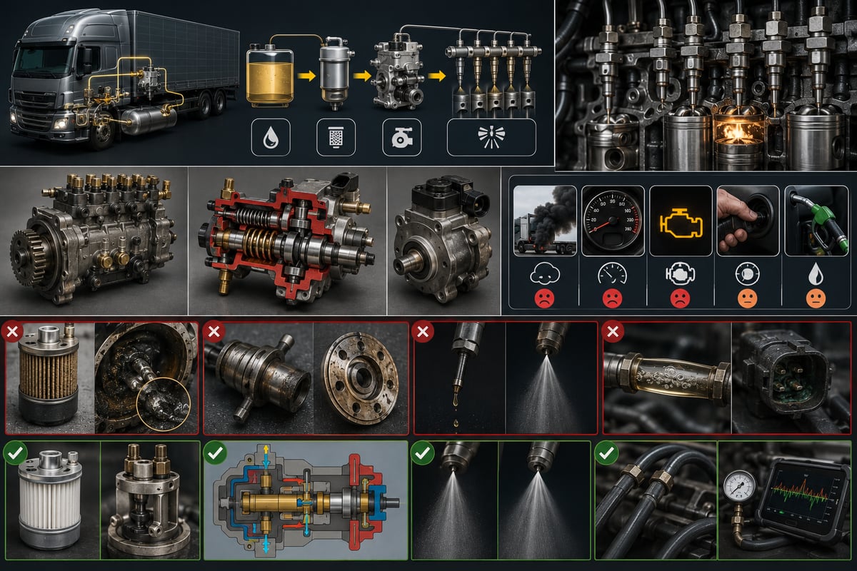
A loaded tractor wakes up reluctant after a long crank on the coldest morning of the week; by afternoon it won't pull the power it should on a grade; that evening, in the heat, it stalls once and only restarts after a key cycle. The driver sums it up in one line on the phone: "the pump's gone." The real question in the shop is which pump, because a heavy-duty diesel doesn't move fuel with a single pump. A separate pump draws fuel from the tank to the engine, an entirely different pump raises that fuel to injection pressure, and most vehicles also carry a small hand-operated pump. All three sit on the same line, all three fail with symptoms that look almost identical, and replacing the wrong one costs both money and a second breakdown. This guide sets out the difference between the two main pumps and the chain that links them: where each pump sits, what it actually does, and which symptom points to which one.
Mapping the diesel fuel supply route: from tank to injector and back
The fuel system isn't a straight line, it's a closed loop. Fuel leaves the tank, gets filtered, is pressurised in two stages, is burned in the cylinders, and whatever isn't burned comes back to the tank through the return line. Reading a pump failure correctly means knowing the order of these stops, because the symptom usually shows up not at the stop where the fault sits, but at the next most sensitive stop downstream.
- Tank and suction strainer: Carries the fuel and keeps coarse dirt away from the pickup. This is where condensation water settles.
- Pre-filter and water separator: Sits on the suction side; separates free water and coarse particles before they reach precision parts.
- Hand primer: The small hand-operated pump on the filter head or on the feed pump body. Fills the line and pushes out air while the engine isn't turning.
- Feed pump: The heart of the low-pressure side. Draws fuel from the tank, passes it through the filters, and delivers it to the high-pressure pump inlet without interruption.
- Main fuel filter: Usually sits after the feed pump, on the pressure side; traps fine particles and protects the micron-tolerance parts downstream.
- High-pressure pump: Raises the incoming clean fuel to injection pressure; on common rail systems a metering valve pressurises only the volume actually needed.
- Common rail and pressure sensor: Stores the pressure, damps out fluctuations, and reports the real value to the control unit.
- High-pressure lines and injectors: Carry the fuel to the cylinders and spray it into the combustion chamber in a metered pattern.
- Return line: Sends the surplus fuel from the injectors, the pump and the regulation elements back to the tank; the same fuel cools these parts on its way back.
The most important thing about this map is that it splits in two. Everything from the suction pickup to the high-pressure pump inlet is the low-pressure side, and there the issue isn't pressure, it's uninterrupted, air-free flow. Everything from the pump outlet to the injector nozzle is the high-pressure side, and there the issue is holding an absolute pressure on target. The whole diagnosis comes down to deciding which of these two zones is at fault.
Low pressure and high pressure: same fuel, two different jobs
The low-pressure side is a transport and cleaning line. The pump's job there isn't to raise fuel pressure, it's to keep the flow continuous: overcoming suction resistance, making up the pressure loss across the filters, and guaranteeing that the high-pressure pump fills completely on every stroke. The high-pressure side is an energy-conversion line; there, fuel is driven past the resistance of the compressed air in the combustion chamber and broken up into micron-sized droplets.
The practical consequence is this: a fault on the low-pressure side usually shows up as a continuity problem, while a fault on the high-pressure side shows up as a level problem. Continuity problems produce intermittent symptoms; the engine runs, then doesn't, and gets worse in heat or under load. Level problems are steady; power is consistently low, and pressure either never reaches target or can't hold it.
| Pump | Job | Typical operating pressure (order of magnitude) | Typical failure symptom | First check |
|---|---|---|---|---|
| Hand primer | Fills the line and pushes air toward the return while the engine isn't turning | Low pressure, generated by hand | Doesn't firm up when pumped, feels spongy, or leaks | Bellows or piston seal condition and check-valve sealing |
| Mechanical feed pump (cam-driven piston type) | Draws fuel from the tank and delivers it through the filter to the pump | Low pressure, on the order of a few bar | Hard starting, stalling in heat, power loss under load | Feed pressure at the pump outlet, vacuum reading on the suction side |
| Gear-type feed pump (built into the high-pressure pump) | Pre-feeds within the same housing and contributes to internal lubrication | Low pressure, on the order of a few bar | Feed shortfall that shows up at idle and clears as revs rise | Comparing inlet pressure at idle versus full load |
| Electric lift pump | Fills the line on key-on and eases hot restarts | Low pressure, on the order of a few bar | No hum on key-on, weakening when hot, cutting out | Supply voltage, fuse, relay and current draw |
| High-pressure pump (common rail) | Raises fuel to injection pressure and meters flow with the metering valve | High pressure, roughly 1,400-2,500 bar | Pressure not reaching target, power loss under load, pressure-deviation fault code | Difference between requested and measured rail pressure, metering-valve duty cycle |
The figures in the table aren't for making a decision on their own, they're for judging whether a measured result is plausible. Two engines from the same maker with the same displacement can call for very different values depending on emission level or injection hardware; the exact limits are read from the OE document for that engine code.
What does a feed pump do? Types and how it works
The feed pump does a more critical job than its name suggests. It doesn't just push fuel forward; it overcomes every bit of resistance on the suction side to reach it: tank depth, a long line, elbows, the strainer, and the water-separating pre-filter. That's why every restriction and every air leak ahead of the feed pump causes far more failures than the pump itself does.
Mechanical piston-type pumps are driven by a cam riding on the camshaft or an eccentric: the cam pushes the piston, the piston pushes the fuel, a spring returns the piston. The defining trait is that flow depends on engine speed, so a pump that's marginal at idle can hide the problem once revs rise. Gear-type pumps are usually built into the high-pressure pump housing and driven off the same shaft; there, separating a feed fault from a high-pressure fault gets difficult unless the measurement point is chosen carefully. Electric lift pumps sit inside the tank or on the chassis, run on key-on, and fill the line before the engine turns.
The hand primer is the simplest member of this family and the most often misunderstood. It isn't a wear part, it's a service tool: after a filter change, a tank drain, or a line disconnection, it refills the system and pushes trapped air back out through the return path. Some self-bleeding systems skip the hand primer entirely; the same job is done by an electric pump that runs on key-on. For removal, seal checks, replacement and upkeep of these pumps, see the feed pump and hand primer guide; this article focuses on the division of labour between the two pumps rather than the step-by-step service work.
What Is a High-Pressure Pump? Function and Failure Symptoms
The high-pressure pump is the part that takes clean fuel from the low-pressure side and raises it to the level needed for the injector to overcome combustion-chamber pressure and atomise it. On common rail systems this is usually done with one or a few radial pistons; an eccentric or cam ring drives the pistons, and on every stroke a small volume of fuel is compressed and sent through a check valve to the common rail. The pump doesn't pressurise more fuel than it needs to; a metering valve at the inlet only draws the flow required at that instant, which keeps unnecessary heating and power draw in check.
The most important detail of this design is that the pump is lubricated and cooled by the very fuel passing through it. There's no separate lubrication circuit; the cam surface, roller, piston and bearing get no protection beyond the thin lubricating film in the diesel itself. That's why most of its failures don't originate in the pump itself, but in whatever sits ahead of it in the chain.
High-pressure pump failure symptoms typically line up like this: the engine runs but doesn't deliver the expected power under load; revs drop on a grade and recovery is slow; the engine never catches at all because the pressure that should build during cranking doesn't; the control unit logs a gap between requested and measured pressure; the metering valve's duty cycle keeps climbing, because the system tries to close the pressure shortfall by demanding more flow. In advanced stages there's fuel weeping from the housing, a leak at the shaft seal, or an unusual metallic sound. The most critical finding is a shiny metallic particle in the filter bowl or the line; that means internal wear has started and swarf is spreading through the system.
The bleeding procedure, removal and installation discipline, and timing and drive details for this pump are a subject of their own and are covered step by step in the diesel injection pump guide. What matters here isn't the procedure itself, but making sure the right pump has been identified before that procedure starts.
Injection pump, diesel pump, feed pump: what does each name actually mean?
Shop-floor naming often hides the technical distinction. "Diesel pump" means the inline pump in one shop, the common rail high-pressure pump in another, and sometimes the feed pump itself. When that same ambiguity carries through to a parts order, the wrong part shows up; and once the wrong part is fitted, the original fault is still there, so a second fault starts getting hunted.
| Everyday name | Technical meaning | Position in the chain | Most often confused with |
|---|---|---|---|
| Diesel pump | Depending on context, the inline pump or the high-pressure pump | Head of the high-pressure side | Feed pump |
| Injection pump | The pump that generates pressure, and on classic systems also timing | Head of the high-pressure side | Metering valve and pressure regulator |
| Feed pump | Low-pressure transfer pump | Between the tank and the main filter | Hand primer, electric lift pump |
| Hand primer, primer bulb, priming pump | Hand-operated filling and bleeding pump | On the filter head or on the feed pump body | Feed pump |
The costliest outcome of this confusion is trying to fix a low-pressure symptom by replacing the high-pressure pump. The new pump goes in, the truck seems fine for a while, then the same symptom comes back, because the condition that was straining the pump is still there. The correct order runs the other way: prove the feed first, then question the pressure.
Why does a weak feed pump damage the high-pressure pump?
The high-pressure pump's piston has to fill a fixed volume on every stroke. When inlet pressure drops, or when there's an air bubble in the fuel, that volume doesn't fill completely; the piston descends into a partial void and sharp pressure drops occur in the compression chamber. That condition sets off three damage mechanisms at once.
The first is dry running. The cam surface, roller and bearings are lubricated only by the thin film of fuel. Cutting the flow, or an air bubble, breaks that film; metal starts touching metal, and the surface first burnishes, then pits. The damage doesn't happen in seconds, it builds up over weeks of marginal feed, which is why the driver says "it was fine, then it just broke."
The second is cavitation. Vapour bubbles that form under insufficient inlet pressure collapse violently once they reach the pressurisation zone; a huge amount of local energy is released in a tiny area, and microscopic particles are torn off the metal surface. Cavitation damage typically leaves a rough, sponge-like surface.
The third is rising fuel temperature. When feed is insufficient the pump works harder and generates more heat; the heated fuel's viscosity and lubricity drop, which thins the lubricating film even further. Heat and wear feed each other in a loop, and the failure shows up most often on hot days and long climbs.
All three mechanisms share the same result: metal swarf, and the swarf doesn't stay in the pump; particles carried by the high-pressure side reach the lines, the common rail, the valves and the injectors. Past that point, replacing only the pump doesn't solve anything, because the contaminated components feed the swarf right back into the new pump. In that situation, manufacturers define a cleaning and renewal scope that covers the lines, rail, valves and injectors; the exact boundaries are read from the OE document.
Further reading
For a plain-language technical overview of this subject, see the reference article on Wikipedia. Always confirm specific figures and procedures against the vehicle manufacturer service data.
From symptom to pump: the diagnostic flow and reading order
The whole of pump diagnosis comes down to a single question: is fuel reaching the high-pressure pump in enough quantity, at enough pressure, and free of air? No measurement taken before that question is answered is safe from being misread. That's why the reading order is fixed: first the vehicle's history and any logged fault data, then the condition of the fuel and the filters, then vacuum on the suction side, then feed pressure at the pump inlet, and only at the end, rail pressure and return flows.
The critical point in this order is that feed pressure should never be read at a single operating point. Low-pressure faults usually show up under only one condition: some only at idle, some only under full load, some only once the fuel has warmed up. A feed pressure that reads normal at idle can collapse under full load and still not throw a fault code. An air bubble in the line is also easy to miss without a clear length of hose; once a bubble is seen, the pump decision is put on hold and the leak is chased first.
| Symptom | Finding pointing to the low-pressure side | Finding pointing to the high-pressure side | First distinguishing measurement |
|---|---|---|---|
| Longer cranking on the first start of the day | Line drained overnight, hand primer feels spongy, bubble in the line | Pressure builds during cranking but stays below threshold | Watching rail pressure and any air bubble in the line together during cranking |
| Stalling when hot, restarting once cool | Feed pressure drops as fuel warms up, electric pump weakens | Internal leakage in the pump grows when hot, pressure won't hold target | Logging feed pressure and rail pressure at the same instant the symptom occurs |
| Power loss under load, can't pull a grade | Filter clogged, suction vacuum high, flow insufficient | Metering valve fully open yet pressure stays below target | Feed pressure at full load together with metering-valve duty cycle |
| Engine won't catch at all | Line empty, full of air, no feed | Pressure never builds during cranking, drive or timing fault | Whether rail pressure builds during cranking |
| Unexplained rise in fuel consumption | External leak on the line, loss on the tank side | Excess return, internal leak, heated fuel | Return-flow measurement and an external-leak sweep |
| Metallic particle in the filter bowl or the line | The low-pressure side doesn't generate this swarf | Internal wear has started in the high-pressure pump | Inspecting the filter contents and scoping the contamination |
The four most common field scenarios and what they really mean
Hard starting and a longer crank
Behind this symptom there's usually a line that drains overnight. Once the vehicle sits, fuel drains back toward the tank, and the morning crank spends its first moments just refilling the line. There are two classic causes: a seal fault on the suction side that lets air in, and a check valve that isn't doing its job. The symptom has a recognisable rhythm: it gets worse the longer the vehicle sits and disappears on short stops; that rhythm is the strongest sign the fault sits on the low-pressure side.
Stalling when hot
As fuel warms up its density and viscosity drop; the same pump moves less mass at the same speed, and a feed that was already marginal turns into a shortfall once it's hot. In electric pumps the warming winding's resistance rises and flow drops. Because internal leaks on the high-pressure side can produce the same symptom, the distinguishing data is the feed pressure logged at the exact moment the symptom occurs.
Power loss under load
If revs drop on a grade and the engine can't recover, the system isn't meeting the flow being demanded. When it's low-pressure in origin, feed pressure collapses noticeably under full load; the most common causes are an overdue filter change, fuel that's waxed up in winter, or a crushed suction line. When it's high-pressure in origin, feed pressure stays normal, but target pressure isn't reached even with the metering valve fully open.
Excess fuel return
Even a healthy system always has some return; the injectors' control volume and the pump's regulation both require it. What matters is a deviation from the normal flow. If only one cylinder's return is elevated, the issue points to that injector; if it's elevated across all cylinders together, it points to pressure regulation or the pump side; if the pump's own return is high on its own, it points directly to an internal leak in the high-pressure pump. How the comparative measurement is done on the injector side is covered in detail in the fuel injector failure symptoms guide.
Where does air get into the system, and how do you find it?
A large share of low-pressure-side faults is air ingress, and the most deceptive part of this fault type is that it doesn't leak fuel outward. While the suction side is running, the inside of the line sits below ambient pressure; a faulty seal doesn't let fuel out, it lets air in. That's why "there's no drip anywhere, so there's no leak" is the wrong conclusion.
| Entry point | How it shows up | Confirmation method |
|---|---|---|
| Filter-head gasket and O-rings | Hard starting that begins right after a filter change | Renewing the seals and cleaning the sealing face |
| Water separator drain cock | Intermittent running that becomes permanent after a drain | Checking that the cock is closed and sealing |
| Suction hoses, clamps and fitting faces | Symptom that changes with vibration, a bubble that progresses over time | Tracking where the bubble starts using a clear length of hose |
| Check valve | Line draining on a long stop, longer cranking in the morning | Logging the relationship between dwell time and crank time |
| Hand primer bellows or piston seal | Primer won't firm up, won't hold pressure | Checking hand-pumping resistance and moisture around the pump |
| In-tank suction pipe and strainer | Symptom that worsens as fuel level drops | Comparing the symptom on a full tank versus a half-full tank |
| Return port inside the tank | Fuel foaming, bubbles carried to the suction side | Assessing the in-tank line layout and its relationship to fuel level |
The most practical way to find the leak is to fit a clear section into the suction line and run the engine: the point where bubbles start narrows down the fault. Second is measuring vacuum on the suction side; if the value is above the manufacturer's limit, the line is restricted. Third is checking the system under sealed pressure; this is only done within the pressure limit defined in the OE document and with the right equipment.
Bleeding logic with the hand primer: when it helps, when it misleads
The hand primer fills the line with fuel and pushes the trapped air ahead of that incompressible liquid, venting it either through a bleed screw or through the return line, depending on the design. The logic is simple, and that's exactly why it has diagnostic value: what happens when you pump it gives a quick read on the low-pressure side.
If the primer firms up after a few strokes, the line has filled and sealing is holding; if the engine still won't run past that point, attention shifts to the high-pressure side. If it never firms up, and just goes soft, then either there's an air leak on the suction side, a check valve isn't doing its job, or the primer's own seal is leaking. If it firms up but softens right after you let go, the line isn't holding pressure; this behaviour usually comes together with a longer morning crank.
There are two common misreadings here. One is assuming that hand-pumped-out air permanently fixes the system; until the source is found, the symptom comes back after every stop. The other is assuming the bleeding procedure is the same on every system. The correct procedure is always the one described in that vehicle's own service documentation.
Fuel quality and the water separator: the deciding link in the chain
One truth holds for fuel pumps: the fuel passing through them is also their oil. That makes fuel quality, in this chain, not a comfort issue but a direct service-life variable. Three contaminants produce three separate kinds of damage.
Water is the most destructive: it strips the fuel's lubricity, starts corrosion on sealing faces, and speeds up surface fatigue under high pressure. Even without water getting in from outside, it forms through condensation; in a half-full tank, air that warms during the day and cools overnight leaves its moisture on the inner surface. In winter this water also brings a risk of freezing and ice plugs. Particulate comes second; hard particles sand down the piston, roller and valve surfaces like an abrasive, and the wear debris itself becomes a new contaminant. Microbial growth develops at the interface between water and fuel; the sludge it produces clogs the filter unexpectedly early, and the symptom looks exactly like insufficient feed.
The water separator's role is broader than its name suggests. It doesn't only hold back water; by separating out the sediment and heavy dirt that come with it, it extends the main filter's life and keeps the resistance ahead of the feed pump low. Left undrained, the bowl fills up, separation efficiency drops, and the trapped water starts carrying through into the rest of the line. In winter the drain interval should be shortened, since condensation increases and any trapped water freezing can block the line entirely.
There's one more seasonal factor: wax crystallising in the cold. Summer-grade fuel clogs the filter's pores at low temperature and produces a symptom that's a dead ringer for a weak feed pump; the vehicle starts in the morning, clears up as it warms, and repeats the exact same thing the next morning. Replacing a pump without making this distinction is one of the most commonly repeated unnecessary jobs in the field.
The return line: the quiet but decisive link
The return line carries unburned fuel back to the tank, and the fuel it carries cools the injectors, the pump and the regulation elements on the way. That second job is easy to overlook: restricting the line means rising temperature and a thinning lubricating film. Once back-pressure builds in the return, the injectors' closing behaviour is disturbed, misfiring starts, and the same condition unsettles the internal balance on the pump side too. The restriction can come from a crushed hose, a section narrowed from the inside, a clogged fitting, or the position of the return port inside the tank. For the result to be valid, hoses have to be kept the same length, free of kinks, and at the same height during the measurement.
What to check before ordering a pump
The list below is the verification chain that should be completed before a pump order goes in. The point isn't to slow the job down, it's to make sure the right part gets replaced and the new one isn't put right back into the same condition.
- Confirm the fuel level and fuel type in the tank; rule out the wrong fuel, water contamination, or fuel that's not right for the season.
- Drain the water separator and inspect what comes out; if there's water, sediment or a gel-like residue, the fault originates on the fuel side.
- Check the change record for the pre-filter and main filter, replace them if needed, and see whether the symptom persists.
- Trace the suction line end to end: look for crushing, cracks, loose clamps, an aged hose, and any connection added later.
- Measure vacuum on the suction side and compare it against the manufacturer's limit; if it's exceeded, clear the restriction first.
- Measure and log feed pressure at the high-pressure pump inlet at idle, at high revs, and under load if possible.
- Look for an air bubble in the line using a clear hose section; if there's a bubble, the pump decision is put on hold and the leak is found first.
- Log the rail pressure built during cranking, the gap between requested and measured pressure while running, and the metering-valve duty cycle.
- Measure return flows separately for the injectors and the pump; this comparison determines which side the leak is on.
- Verify the electrical side: the metering valve's command signal and resistance, the electric pump's voltage and current, fuses, relays and chassis connections.
- Check the mechanical drive: pump gear, coupling, belt and timing marks; a drive fault can make the pump look guilty.
- Inspect the dirt coming out of the filter bowl and the line; if there's a metallic particle, accept that the replacement scope can't stay limited to the pump.
Once these twelve items are complete, the pump being replaced is a decision backed by measurement, not a guess. The same discipline applies after the replacement too: the same measurements are repeated once the new part is fitted, and the improvement is put on record.
Technical values and general reference ranges
The table below gathers the figures needed most often in the field as orders of magnitude; the exact limit is always in the OE service manual for the vehicle's engine and chassis code.
| Value | General reference range or criterion | Interpretation |
|---|---|---|
| Suction-side vacuum | Compared against the manufacturer's stated limit | Exceeding the limit means a clogged pre-filter or a restricted suction line |
| Feed (low) pressure | On the order of a few bar | Should be read separately at idle, high revs and under load |
| Common rail operating pressure | Roughly 1,400-2,500 bar | Set by the control unit based on revs and load |
| Mechanical inline pump line pressure | On the order of a few hundred bar | Assessed on a test bench against OE values |
| Pressure that must build during cranking | An engine-code-specific threshold | If the threshold doesn't build, the engine never catches; diagnosis starts here |
| Metering-valve duty cycle | Not an absolute figure, judged against that engine's own baseline | A steadily rising duty cycle shows the system is forcing the pressure to hold |
| Return flow | Not an absolute number, a comparative distribution | A difference between cylinders points to an injector, an overall rise points to the chain |
| Effect of fuel temperature | Feed margin narrows as temperature rises | Symptoms that appear only when hot suggest the low-pressure side |
| Pump mounting and drive torque | The value and tightening sequence in the OE manual | Wrong torque causes housing distortion and leaks |
| Contamination-scope decision | Widened when a metallic particle is found | Replacing the pump alone lets the fault repeat |
Maintenance discipline: the habits that keep the feed chain healthy
Neither the feed pump nor the high-pressure pump has any maintenance of its own; maintaining both really means maintaining the fuel that passes through them. The practices that make a measurable difference across a fleet come down to a handful of points.
- Filter discipline: Change the pre-filter and main filter on whichever comes first, mileage or time; filtration grade should never be coarser than the engine calls for.
- Draining the water separator: Drain it on a regular schedule, more often in winter, and check what comes out by eye.
- Keeping the tank full: A tank left full overnight cuts condensation; a half-full tank generates its own water in winter.
- Auditing the fuel source: Check the fuelling point, the bottom of any bulk tank, and the filter on any in-house fleet pump on a regular basis.
- Seasonal-transition check: Review the summer-grade fuel left in the tank and the filter's age before the cold season sets in.
- Line sweep: Inspect suction hoses, clamps, filter-head seals and the return line for moisture, chafing and ageing.
- Logging live data: Even with no warning light on, read feed pressure, rail pressure and metering-valve duty cycle on a schedule; the trend is the earliest warning of a fault.
- Keeping a service record: Log the type of pump replaced, the measured values and the reason for replacement in the vehicle file; only that record shows the root of a repeat failure.
In the end, the fuel supply chain is the work of two interdependent pressure worlds, not a single pump. The low-pressure side is responsible for delivering fuel clean, uninterrupted and free of air; the high-pressure side is responsible for putting that fuel at the right level at the right moment. Because the symptoms overlap, the right diagnosis is found by following the order, not the part: first prove the fuel is clean, then that the feed is adequate, then that the pressure builds; the pump is questioned last. In every case, the vehicle's current OE service documentation for its engine and chassis code is authoritative.
In many applications, this pump group carries a separate electrically operated control element that drives the fuel shut-off valve; its symptoms and testing are the subject of the solenoid coil faults guide.
Shop this part: Injector Pump
In-depth technical guide: For fault diagnosis, step-by-step replacement and service intervals: Feed Pump & Hand Primer: Faults, Replacement, Maintenance
Main guide: What Is a Fuel Injector? How to Recognize Injector Failure Symptoms
Tags
Frequently Asked Questions
- What is the difference between a feed pump and an injection pump?
- They work in two separate parts of the fuel chain. The feed pump sits on the low-pressure side: it draws fuel from the tank, overcomes suction resistance and filter losses, and delivers it to the high-pressure pump inlet without interruption, running at only a few bar. The injection pump, meaning the high-pressure pump, takes that clean fuel and raises it to injection pressure; on common rail systems that's roughly 1,400-2,500 bar. In short, the feed pump is responsible for keeping the flow continuous, and the injection pump is responsible for the level of pressure.
- What are the failure symptoms of a high-pressure pump?
- The most common ones are power loss under load and an inability to pull a grade, the engine never catching because the pressure that should build during cranking doesn't, a persistent gap between requested and measured rail pressure, and a metering-valve duty cycle that keeps climbing. In advanced stages there's fuel weeping from the housing, a leak at the shaft seal, or an unusual metallic sound. The most critical finding is a shiny metallic particle in the filter bowl or the line; that means internal wear has started and swarf is spreading through the system.
- What are the symptoms of a feed pump failure?
- Feed faults usually produce intermittent symptoms: a longer crank on the first start of the day, stalling when hot and restarting once cool, power loss under load, rough running at idle, and occasionally the engine not catching at all. The defining trait is that the symptom shows up under only one condition; on some vehicles only at idle, on others only under full load, on others only once the fuel has warmed up. That's why feed pressure has to be measured separately at idle, at high revs and under load, not at a single operating point.
- The engine stalls when hot, which pump should I suspect?
- As fuel warms up its density and viscosity drop; the same pump moves less mass at the same speed, and a feed pump that was already marginal turns into a shortfall once it's hot. In electric lift pumps the warming winding's resistance rises and flow drops. Internal leaks on the high-pressure side can produce the same symptom, so the distinguishing data is the feed pressure and rail pressure logged at the same moment the stall happens: if feed pressure collapses, look at the low-pressure side; if feed stays normal and rail pressure won't hold, look at the high-pressure pump.
- Why does the engine take longer to start in the morning?
- Behind this there's usually a line that drains overnight. Once the vehicle sits, fuel drains back toward the tank, and the crank spends its first moments just refilling the line. There are two classic causes: a seal fault on the suction side that lets air in, and a check valve that isn't doing its job. The symptom has a recognisable rhythm, getting worse the longer the vehicle sits and disappearing on short stops; that rhythm is the strongest sign the fault sits on the low-pressure side, and it calls for chasing a leak before replacing any pump.
- How can I tell if there's air in the fuel system, and where does it get in?
- The most practical method is fitting a clear section into the suction line, running the engine, and watching where the bubbles start; vacuum on the suction side is also worth measuring. The deceptive part of this fault type is that it doesn't leak fuel outward: while the suction side is running the inside of the line sits below ambient pressure, so a faulty seal lets air in rather than letting fuel out. The most common entry points are the filter-head gasket and O-rings, the water separator's drain cock, suction hoses and clamps, the check valve, and the hand primer's own seal.
- What does it mean if the hand primer won't get firm?
- The hand primer fills the line with fuel and pushes trapped air ahead of it, so what happens when you pump it gives a quick read on the low-pressure side. If it firms up after a few strokes, the line has filled and sealing is holding; if the engine still won't run, attention shifts to the high-pressure side. If it never firms up and just goes soft, there's an air leak on the suction side, a check valve isn't doing its job, or the primer's own seal is leaking. If it firms up but softens right after you let go, the line isn't holding pressure, which usually comes with a longer morning crank.
- Can a weak feed pump damage the high-pressure pump?
- Yes, this is the most common chain-reaction failure. The high-pressure pump has no separate lubrication circuit; its cam surface, roller, piston and bearing are lubricated only by the thin film of the fuel passing through. When inlet pressure drops or an air bubble reaches the pump, three mechanisms act together: dry running causes metal-to-metal contact, cavitation tears microscopic particles from the surface, and rising fuel temperature thins the lubricating film further. The shared result is metal swarf, which then travels on to the lines, the common rail, the valves and the injectors.
- Is excess fuel return a sign of pump failure?
- Not always. Even a healthy system always has some return, since the injectors' control volume and the pump's regulation both require it. What matters is a deviation from the normal flow. If only one cylinder's return is elevated, the issue points to that injector; if it's elevated across all cylinders together, it points to pressure regulation or the high-pressure side as a whole; if the pump's own return is high on its own, it points directly to an internal leak in the high-pressure pump. Hoses need to be kept the same length, kink-free and at the same height for the comparison to be valid.
- What measurements should be taken before replacing a pump?
- First the fuel itself is confirmed: level, type, water content and seasonal suitability. Then the water separator is drained and what comes out is inspected, the filter change record is checked, and the suction line is traced end to end for crushing, cracks and loose clamps. Next, vacuum on the suction side and feed pressure at the high-pressure pump inlet are measured at idle, high revs and, if possible, under load, and a clear hose section is used to look for an air bubble. Finally, rail pressure during cranking, the requested-versus-measured pressure gap, metering-valve duty cycle and return flows are logged, along with the electrical supply and the mechanical drive.
Related Articles

Fuel Water Separator Filter: Symptoms, Replacement & Care
Truck fuel water separator filter and housing: how it works, water sensor, drain valve, heater, fault symptoms, replacement, bleeding and maintenance.
Solenoid Coil: Faults, Testing, Replacement and Maintenance
Understand how a solenoid coil works, spot open or shorted windings with a multimeter, replace it correctly and extend its service life on trucks.
Diesel Injection Line & Fuel Pipe: Faults, Repair, Maintenance
Heavy truck injection line and fuel pipe guide: high-pressure vs supply line, leak and air ingress diagnosis, torque sequence, replacement and maintenance.


