Air Brake System: How It Works on Heavy Commercial Vehicles
When a tractor unit rolls into the workshop, the complaint is not always "the brakes don't hold". More often it is "the brakes hold late". The driver feels a
When a tractor unit rolls into the workshop, the complaint is not always "the brakes don't hold". More often it is "the brakes hold late". The driver feels a short but unmistakable gap between the moment the pedal goes down and the moment the vehicle actually starts to slow, and that gap is different from what he is used to. The gauge reads normal, reservoir pressure sits inside the band, lining thickness is adequate, and there is no warning stored on the dash. Measured on a brake tester, the braking force is not down either. The force is not missing; the force arrives late. On an air brake system these are two completely separate problems, and they are not solved in the same place.
This guide is devoted to a single question: after the pedal is applied, how long does it take for braking force to reach the brake chamber, where exactly is that pneumatic lag created, and how is it shortened? The subject here is not the quantity of air, but the travel time of the air that is already there. How much air the system produces, how much it stores and how much each consumer spends is a separate subject and belongs to the compressor guides. Everything on this page is handled on the time axis.
What is response time on an air brake system and why is it different from hydraulics?
Response time is the interval between the moment the driver starts to apply the pedal and the moment pressure in the brake chamber reaches a defined level. Two separate quantities hide inside that definition, and confusing them sends the diagnosis down the wrong road from the start. The first is dead time: the pedal has moved, but there is still no pressure at all in the chamber. The second is build-up time: pressure has started to appear in the chamber and is climbing towards the target level. Total response time is the sum of the two; dead time is usually created on the signal path, while build-up time is created on the delivery path and in the volume of the chamber itself.
The same definition has a reverse direction as well: release time. After the pedal is released, exhausting the air out of the chamber and letting the force disappear also takes time, and that time is often longer than the apply time. A large share of the delays missed in the field sit here; when release slows down, the vehicle has no trouble stopping, the brakes simply carry on down the road without fully letting go, and that comes back as heat.
The difference from a hydraulic system rests on a single physical fact: liquid is practically incompressible, air is compressible. In a hydraulic circuit the line is already full of fluid and movement is transferred to the far end almost instantly. On an air system, force can only be created once the volume of the line and the chamber has been filled to a higher pressure; filling is a flow job, and flow takes time. That is why an air brake system carries a lag that can never be reduced to zero. The engineering task is not to eliminate that lag but to keep it below an acceptable limit.
That limit is not arbitrary: regulations define an upper limit for the time taken to reach a given pressure level at the least favourably placed brake chamber. The numerical value of the limit changes with vehicle class and measurement method, so no figure is given here; memorising an unverified threshold is riskier than not measuring at all.
How does an air brake system work? A short summary from a timing point of view
On an air brake system the compressor driven by the engine produces compressed air, that air is conditioned, taken into reservoirs and held there ready. When the driver applies the pedal, no new energy is generated; a decision is made about how much of the energy already waiting in the reservoir goes to the brake chambers. The pedal is not a force transmitter but a control device: depending on how far it is applied, it creates a pressure demand. That demand travels along the lines, turns into pressure at the chambers, the diaphragm in the chamber pushes the pushrod, and the mechanical linkage presses the lining against the friction surface.
Seen on the time axis, this chain has three different speeds. Stored energy is already there; its readiness time is zero. The driver's demand travels along the lines at filling speed. Force itself waits for the mechanical clearances to be taken up. A vehicle that holds late means one of these three speeds has degraded, and each one is hunted in a different place.
A component-by-component description of the system, the circuit logic, the fault list and the diagnostic flow are outside the scope of this article; all of that is covered in the guide Air Brake Systems in Heavy Commercial Vehicles: Working Principle, Component Glossary and Comprehensive Fault-Finding Guide. From here on, only the clock matters: where the time is spent.
Which stations does the force pass through on its way to the chamber after the pedal is applied?
Lag is not created in one place; it accumulates in small shares at consecutive stations. Each station looks unimportant on its own, and their sum is the gap the driver feels.
- Pedal free play and mechanical linkage. The free travel the pedal takes before it moves the valve is time passing without any pneumatic event at all; on a linkage that has drifted out of adjustment, this play grows.
- The cracking point of the valve. The control valve passes no air until a certain amount of movement is reached. This threshold is part of the design; if the springs have fatigued or there is contamination inside, it rises and dead time gets longer.
- Filling the signal line. For the pressure demand to reach the point it will control, the volume of the small-bore line itself must be filled; the longer the line, the bigger this share.
- The controlled valve answering. The delivery port does not open until pressure at the control port rises far enough to move the piston inside the valve. A second threshold is crossed here.
- The delivery path opening. Once the port is open, air starts to flow from the nearby reservoir to the chamber. Everything up to this point is dead time; there is still no meaningful pressure in the chamber.
- Filling the chamber volume. The volume behind the diaphragm is filled up to the pressure that will create force. The main body of build-up time sits here, and it grows as the volume grows.
- Taking up the clearances. The pushrod travels, the clearances in the mechanical linkage are collected, and the lining touches the friction surface. At this stage there is pressure but still no retarding force.
- Force rising. Once contact is made, every further increase in pressure converts directly into force and the vehicle starts to slow. This is the moment the driver calls "the brakes bit".
The first five of these eight stations belong to the signal side and the last three to the power side; that distinction cannot be made without knowing when pressure actually began to appear at the chamber.
Where pneumatic lag is created: separating the signal path from the delivery path
The key to understanding the timing architecture is this distinction: what a line carries is either information or power. The signal path carries the message "brake this much" and only needs to fill a small volume to do so. The delivery path carries the air that will fill the chambers and must fill a large volume. When both jobs are loaded onto the same line, one long, small-bore pipe carries both the information and the power; the chambers at the rear of the vehicle then have to wait for air leaving the valve under the cab to travel the entire distance.
This is where the lag is really created, and it is not where most people assume. A pressure wave travels along a line very quickly; a change at one end is felt at the other end almost immediately. But pressure starting to change at a point is not the same thing as that point reaching working pressure. What eats time is not the journey of the wave but the filling of the volume, and filling speed is limited by the narrowest point on the road.
That is why modern brake circuits are deliberately split in two: small-bore control lines cover long distances but fill small volumes; large-bore delivery lines fill large volumes but stay short. The whole design is built on preventing long distance and large volume from meeting on the same path. If a repair unknowingly breaks that separation, the vehicle does not lose force, it loses time, and that loss shows on no gauge at all.
How do line diameter and line length change response time?
A line affects timing in two ways, and both work in the same direction. The first is volume: as the line gets longer or larger in bore, the air volume that has to be filled grows. The second is resistance: air loses pressure to friction as it travels inside a pipe, and that loss increases with length and rises steeply as the bore narrows.
The two do not behave the same way with respect to diameter, and that is the critical point. When the cross-section narrows, volume falls proportionally; flow capacity, however, falls under a much harsher relationship. The outcome is a clear net loss: a narrow line lengthens the total time even though the volume it has to fill is smaller. The reverse is also true; going one size up on a delivery line usually shortens the time even though it increases the volume.
On the length side the situation is more direct: making the line longer increases volume and resistance together. That explains why the geometry of the vehicle governs brake timing. On a long-wheelbase vehicle the rear-axle chamber sits much further from the valve under the cab than the front-axle chamber does, and if nothing is done about it the rear brakes will always hold late. The same reasoning also explains why the gap between tractor and trailer is even wider.
On the release side the effect of the line is even more pronounced; a chamber at the end of a long line fills late and exhausts later still. The most common silent mistake is renewing a line during a repair with whatever pipe is on the shelf: a pipe whose outside diameter fits but whose bore is narrow will not leak, it will hold pressure, and it will show on no gauge; the only thing it does is lengthen the response time of that circuit.
What do fittings, elbows and cross-section restrictions add to the lag?
The flow capacity of a circuit is set not by the pipe itself but by the narrowest point along the road. A narrow fitting placed in the middle of a large-bore delivery line drops the whole line to the capacity of that fitting; pipe size no longer means anything. So when you are hunting lag, the transition components along the line must be counted as carefully as its length.
The typical items that add their share to the time are as follows. The internal bore of fittings is usually smaller than the pipe they connect to, and several fittings in series stack those restrictions. Sharp elbows force the flow to change direction; taking the same turn with a wide-radius bend is cheaper in time. Tee connections split the flow, and one leg always fills later than the other. Quick-connect couplings make assembly easier, but the mechanism inside them narrows the cross-section. Crushed pipes and badly cut pipe ends look sound from the outside while reducing the bore or leaving a burr that forms a permanent obstruction to flow.
What all these items have in common is that none of them presents as a fault: they pass a leak test, they hold pressure, they look tidy to the eye. Their effect appears only on the time axis, and as long as that axis is not measured it stays invisible.
Why does a relay valve shorten the lag?
The relay valve is the hardware answer to the principle "do not let long distance meet large volume", and from a timing point of view it does one single job: it separates the control signal from the delivery air. The small-bore control line leaving the area under the cab travels a long way to the rear of the vehicle, but it only has to fill the small control volume of the relay valve, and that volume fills quickly. The moment the relay valve senses the signal, it passes air taken from the reservoir right beside it to the chambers over a short, large-bore path. The chamber no longer waits for air coming from the other end of the vehicle.
The gain sits in two places. On the apply side, build-up time shortens because the large volume of the chamber is fed through a short, wide path. On the release side the gain is even more pronounced: instead of sending the air in the chamber back down the long line, the relay valve exhausts it to atmosphere where it stands. The exhaust path then becomes even shorter than the filling path, and the brakes let go faster.
Relay valves have a cracking point, and in some applications that threshold is chosen differently in order to tune the timing of the axles relative to one another. For that reason, swapping a relay valve for one with a different character on the grounds that "it does the same job" upsets not the force balance but the timing balance. Where the valve sits in the circuit and how the lines connect to one another is a separate subject; for that, see the guide How to Read an Air Brake Diagram: Circuit Guide.
What does trailer line length add to the response of the rear axles?
Taken on its own, the tractor unit's line lengths are limited by the chassis length. When a trailer is coupled, a completely new layer of length is added to the circuit, and that layer is usually longer than the tractor's own lines. The trailer brakes do not come in at the same moment as the tractor's; they come in after this added distance has been covered.
The layers that add their share to the time, in order, are these: the valve on the tractor that generates the trailer control signal, the line length on the tractor, the couplings and the flexible hoses between the units, the valve arrangement at the trailer inlet, and the lines running along the trailer chassis to the chambers. On a long semi-trailer the sum of that chain can be several times the length of the line running from under the tractor's cab to its rear axle. The trailer's own relay arrangement exists to absorb the effect of this length; when it is out of action or slow, the trailer brakes fall noticeably behind.
In practice the weakest link is the flexible coupling area. A hose that has aged and swollen internally can look sound from the outside while its bore has narrowed; when the filters in the coupling heads collect dirt, flow drops; a hose that is chafing or bent too tightly gives the same result. None of these leaks; they only eat time.
Why does timing compatibility between tractor and trailer matter?
In a combination the brakes never come on at exactly the same moment; one side always engages before the other. What matters is not the absence of that difference but keeping it inside an acceptable band. Outside the band, two pictures emerge, and neither is wanted.
If the trailer brakes are late, the tractor carries the deceleration alone for a while. The trailer pushes from behind, the load on the tractor's rear axle increases, the force balance between axles is upset, and the risk of losing stability on a slippery surface or in a bend grows. On top of that, the tractor's brake equipment wears and heats faster because it is doing more than its share. Linings that always run out on the tractor side are usually not a material problem but a timing problem.
In the opposite case, if the trailer brakes come in noticeably early or hard, the trailer drags the combination backwards; trailer linings and tyres are overloaded, and the tendency for wheels to lock at light load increases. The common symptom of both pictures is an unexplained difference in lining life between two vehicles running the same duty profile.
Timing compatibility is assessed against a defined compatibility band during type approval; the numerical equivalents of that band change with vehicle and trailer class, so no figure is given here. The principle to hold on to in the field is this: timing is not a property of the tractor alone, it is a property of the combination, and it can be upset even when both sides are individually maintained correctly. Where an electronically controlled tractor works with a purely pneumatically controlled trailer, the trailer inherits the natural lag of the pneumatic control line; that is not a fault but an architectural difference, although it does widen the gap.
How does the electrical signal of EBS shorten pneumatic lag?
The contribution EBS makes to timing can be summarised in one sentence: the signal now travels by being transmitted, not by filling. Movement at the pedal is converted into an electrical quantity and reaches the control units at the axles over a cable. Since no volume has to be filled for the electrical signal to travel, the lag on the signal side effectively disappears. Because the bulk of dead time is created on the signal path, the most noticeable reduction in total response time comes from here.
The second contribution is layout: because the control units sit close to the axles, the air that will fill the chamber is delivered over a short, wide path. The third contribution is balancing; the system can manage the natural timing difference between axles and, by triggering the trailing axle early, can bring the brakes of the combination closer together.
Against that, two points must be underlined. First, the pneumatic control line does not disappear; if there is an interruption on the electrical side, the system reverts to pneumatic control and the timing moves back towards that of a vehicle without electronics. Second, and more important, electronic control does not touch the mechanical half of the chain. The chamber volume still has to be filled, the pushrod still has to travel, the clearances still have to be taken up. A brake that is out of adjustment holds late on an electronically controlled vehicle too.
The relationship between chamber filling time and stroke
The brake chamber is the largest volume at the end of the time chain, and that volume is not fixed. The further the pushrod has to travel, the larger the volume that must be filled before force is created. The relationship is direct: as stroke lengthens, more air is needed and the time for that air to flow grows. The result is the picture the driver describes as "the pedal has got deeper" or "the brakes hold late".
That explains why adjustment is not only a matter of force. On a brake that has drifted out of adjustment, two losses occur at once: force falls, because it is produced at a less favourable position of the mechanical linkage; and the moment force appears is delayed, because a larger volume has to be filled. If one side of an axle is adjusted and the other is not, the two wheels hold at different moments and with different intensity; that is a direct axle imbalance.
Chamber size is part of the same equation: a chamber with a larger effective area produces more force, but the volume to be filled is larger too and it fills more slowly through the same delivery path. Fitting chambers of different sizes to the two wheels of the same axle is one of the clearest causes of artificial imbalance.
| Factor | Half in which the lag is created | Effect on apply time | Effect on release time |
|---|---|---|---|
| Lengthened control line | Signal path | Dead time lengthens | Limited |
| Restricted delivery cross-section | Power path | Build-up time lengthens | Lengthens noticeably |
| Narrow fittings and sharp elbows in series | Power path | Build-up time lengthens | Lengthens |
| Relay arrangement out of action | Both | Lengthens noticeably | Lengthens noticeably |
| Long and aged trailer hose | Both | Lengthens | Lengthens |
| Brake out of adjustment, extended stroke | Mechanical half | Lengthens and force falls | Lengthens |
| Rising valve cracking point | Signal path | Dead time lengthens | Variable |
| Moisture and icing collecting at a restriction | Both | Lengthens seasonally | Lengthens seasonally |
The effects in the table are for qualitative comparison; none of them is a threshold or an acceptance criterion.
Do cold weather and altitude affect response time?
The short answer is yes, but in a different order of importance from the one people expect. Cold acts in two ways, and the ranking is usually understood the wrong way round.
Material stiffening. Diaphragms, seals and the elastomer components inside valves stiffen at low temperature; the force needed to move them increases. That raises valve thresholds slightly and adds a small share to dead time. Grease in the mechanical linkage also thickens in the cold, and taking up the clearances takes a little longer.
Moisture freezing at restrictions. This is the larger of the two effects, and its cause is not physical but maintenance-related. Moisture carried in the circuit condenses at the points where the cross-section narrows; when the temperature drops, ice forms there and an already narrow passage closes up further. On such a circuit, response time is normal in mild weather and noticeably long in the cold. This is the most typical explanation for a brake that is sluggish in the morning and returns to normal as the day warms up. Moisture management and winter preparation are a separate subject and are covered in the guide Air Brake Systems: Working Principle, Maintenance and Safety Tips.
On the altitude side the effect works in two directions and its magnitude is limited. Ambient pressure falls with height; exhausting the air in the chamber to atmosphere becomes somewhat easier, while the differential pressure the system works across and the density of the air change. In practice there is no solid basis for saying that a vehicle holds noticeably late because of altitude alone; altitude belongs at the bottom of the diagnostic list, not the top.
How is response time observed in the field?
Measuring response time numerically requires a defined method, suitable pressure test points and calibrated equipment; that is work for an authorised measurement facility. In the workshop, however, comparison-based observations can be made without quoting a numerical threshold. The essence of the method is this: instead of looking for an absolute time, check whether two events that should happen at the same moment really do.
- Watch both sides of the same axle together. With the vehicle safely secured, the start of pushrod movement on both sides is observed as the pedal is applied slowly; if one side starts noticeably later, there is a lag there caused by adjustment, line or valve.
- Observe the sequence between front and rear. The rear axle lagging the front can be part of the design; but if the difference is noticeably greater than what is seen on a healthy example of the same model, it should be investigated.
- Compare tractor and trailer under the same application. If movement on the trailer side starts well after the tractor, the lag is in the trailer line or in the trailer's own valve arrangement.
- Watch the release side separately. The return of the pushrods is observed after the pedal is released; if one side returns late or does not return fully, the exhaust path on that circuit is restricted.
- Listen to the sound. Comparing the duration of the chamber filling sound and the character of the exhaust sound between the two sides makes the difference audible. It is not proof on its own; it shows you where to look.
- Compare within the fleet. Sister vehicles of the same model, the same specification and a similar duty profile are the most reliable reference available. If one vehicle behaves noticeably differently from its sisters, the difference comes from that vehicle.
These observations do not produce a pass or fail decision; they only establish the need for measurement. The rule to hold on to here is this: lag is visible when it is compared and invisible when it is looked at on its own.
What do the regulations require for response time and stopping?
Response time is not left to interpretation — it is a type-approval limit. In Europe, UNECE Regulation No. 13 caps the service brake at 0.6 seconds from the moment the control is applied to the point where the brake chamber reaches 75% of its asymptotic pressure. In the United States the federal air brake equipment standard, FMVSS 121 (49 CFR 571.121), sets its own actuation- and release-timing and reservoir requirements, while the on-road braking performance a heavy vehicle must actually achieve is defined separately in 49 CFR 393.52. A system that responds late eats into the margin those rules were written to guarantee, which is why the lag is a compliance and safety quantity, not a comfort one. Treat the 0.6-second figure as the regulatory ceiling and always confirm the current limits against the up-to-date regulation and the vehicle manufacturer service data.
Outside the United States the equivalent duties sit in national law. In the United Kingdom, regulation 18 of the Road Vehicles (Construction and Use) Regulations 1986 requires every part of the braking system to be maintained in good working order. In Canada, air brake systems fall under the Motor Vehicle Safety Regulations, which contain CMVSS 121.
What does the lag mean in terms of stopping distance?
Why response time is a safety quantity becomes clear when it is converted into distance. Total stopping distance is made up of three parts: the distance covered until the driver perceives the hazard and applies the pedal, the distance covered until the system builds up braking force, and the distance covered while the vehicle decelerates to a stop after the force exists. Through the middle part the vehicle has barely slowed at all; for that whole interval the full speed is retained.
The table below makes no claim about the lag of any brake system; it only shows the arithmetic of converting speed into distance. The distance a vehicle covers in one second is found by dividing its speed in kilometres per hour by 3.6.
| Speed (km/h) | Distance covered in one second (m) | Distance covered in half a second (m) |
|---|---|---|
| 30 | 8.3 | 4.2 |
| 50 | 13.9 | 6.9 |
| 60 | 16.7 | 8.3 |
| 80 | 22.2 | 11.1 |
| 90 | 25.0 | 12.5 |
What the table says is simple: differences that look tiny on the time axis are measured in vehicle lengths on the distance axis. And that distance cannot be won back by increasing braking force, because the loss comes not from the force being insufficient but from the force not yet existing.
This is why timing deserves to be taken as seriously as force in maintenance planning. The way to speed up the response of a circuit is not to fit a stronger part; it is to shorten the path, protect the cross-section, avoid adding volume and keep the mechanical clearances in adjustment. VADEN treats the components it manufactures for heavy commercial vehicle air brake systems within exactly this whole; a correctly selected and correctly installed part does not only produce force, it also keeps the response time of the system inside the band it was designed for. Every explanation here is a conceptual reference; for vehicle-specific values and acceptance limits, the vehicle manufacturer's current service manual is decisive.
If you want to see the whole valve family in the circuit together with its duties and typical failure symptoms, our truck air brake valves guide takes each valve in turn.
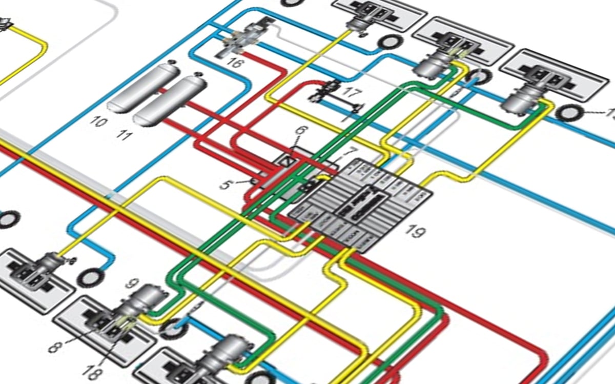
If you prefer to follow how the circuits connect in a visual layout, our air brake system diagram guide traces the installation circuit by circuit.
Shop this part: Brake System
Tags
Frequently Asked Questions
- What is response time on an air brake?
- Response time is the interval between the moment the driver starts to apply the pedal and the moment pressure in the brake chamber reaches a defined level. It has two components: dead time, during which no pressure has yet appeared in the chamber, and build-up time, during which pressure climbs to the target level. This time arises because air is compressible and volumes have to be filled; it cannot be reduced to zero, but it can be shortened by shortening the path and protecting the cross-section.
- How does an air brake system work?
- The compressor driven by the engine produces compressed air, which is conditioned and held ready in the reservoirs. When the driver applies the pedal, no new energy is generated; a decision is made about how much of the waiting air goes to the brake chambers. The control valve creates a pressure demand according to how far the pedal is applied, the demand travels along the lines, turns into pressure at the chambers, and the diaphragm pushes the pushrod so that the lining is pressed against the friction surface. The component-by-component description of the system and the fault-finding process are covered in the comprehensive air brake system guide.
- Why don't the brakes bite immediately after the pedal goes down?
- Because volumes have to be filled before force can be created. Pedal free play, the cracking point of the valve, filling the control line, the controlled valve answering, filling the chamber volume and taking up the mechanical clearances are consecutive stations, and each adds its share to the time. If the total has become noticeable, the first step is to separate whether pressure starts late at the chamber or climbs slowly once it has started.
- Does a relay valve really shorten response time?
- Yes, and it does so in two separate places. It lets the long control line fill only a small control volume, while the chamber is fed from the nearby reservoir over a short, wide path; that shortens build-up time. On release, instead of sending the air in the chamber back down the long line, it exhausts it to atmosphere where it stands. When the relay arrangement is out of action, both gains are lost.
- Why do the trailer brakes hold after the tractor's?
- Because the distance to be covered is longer: the tractor's trailer control valve, the lines on the tractor, the couplings and flexible hoses, the trailer's valve arrangement and the lines running along the trailer chassis each add their share to the time in turn. The trailer's own relay arrangement exists to absorb this effect. If there is a noticeable lag, examine the flexible coupling area and hose condition first, then the trailer valve arrangement.
- Is it a problem to replace an air line with a smaller-bore pipe?
- Yes, and the problem shows up in timing rather than sealing. When the cross-section narrows, flow capacity falls far more steeply than the volume does; the filling and exhausting times of that circuit lengthen. A pipe whose outside diameter fits but whose bore is narrow gives no symptom during assembly, holds pressure and shows on no gauge. When replacing lines and fittings, internal bore must be considered at least as carefully as external thread size, and the decision must be made according to the vehicle's current service documentation.
- Does pneumatic lag disappear completely on a vehicle fitted with EBS?
- No. Electronic control removes the bulk of dead time because the signal travels by being transmitted rather than by filling a volume, and having the control units close to the axles also shortens the delivery path. But the chamber volume is still filled, the pushrod still travels, the mechanical clearances are still taken up; a brake out of adjustment holds late on an electronically controlled vehicle too. If there is an interruption on the electrical side, the system reverts to pneumatic control and the timing slows down.
- Does response time change if brake adjustment is out?
- It does, and two losses occur at the same time. As the pushrod travel lengthens, the chamber volume that must be filled before force is created grows and the chamber takes longer to fill; in addition, force falls because it is produced at a less favourable position of the mechanical linkage. Adjustment is a maintenance item that governs timing just as much as it governs force.
- Is it normal for the brakes to hold late in cold weather?
- A small difference can be expected: elastomer components stiffen, grease thickens and valve thresholds rise slightly. But a noticeable lag is not normal, and its most common cause is not physics but moisture. When moisture condensing at points where the cross-section narrows freezes, the passage closes up; the vehicle is sluggish in the morning and returns to normal as the day warms. In that picture, the cause should be sought in the moisture in the system rather than in the cold itself.
- Can a definite figure be given for response time?
- It can be given for a specific vehicle and circuit, but not as a universally valid number. Regulations define an upper limit for the time taken to reach a given pressure level at the least favourably placed brake chamber; the numerical value of that limit changes with vehicle class, measurement method and the version of the regulation. The valid figure for a vehicle is found by measuring it with the defined method and suitable equipment; for acceptance limits, the vehicle manufacturer's current service manual is decisive.
Related Articles
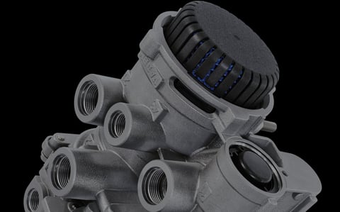
Truck Air Brake Valves Explained: Types, Functions and Failure Symptoms
Truck air brake valves explained: what relay, ALB, foot brake and trailer valves do, their failure symptoms, and how to diagnose faults with a pressure gauge set.
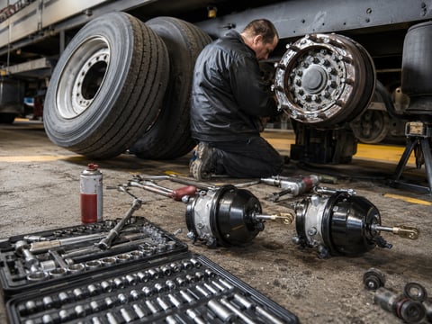
Air Brake Chamber Explained: Types, Sizes, Failure Symptoms & Replacement
Truck and trailer inspection reports rarely say the brake chamber is defective; they report brake force imbalance. Chamber types, sizes, symptoms and replacement.
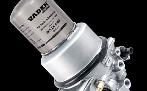
Heavy-Duty Truck Air Dryer: Bendix, WABCO & When to Replace the Cartridge
Almost every question about a truck's air dryer needs one piece of information before it can be answered: which family the dryer on that vehicle belongs to.


