Relay Valve & ABS Relay Valve: Faults, Replacement & Care
Heavy commercial vehicle relay valve and ABS relay valve guide: how it works, fault symptoms, diagnosis, replacement steps, torque values and maintenance tips.
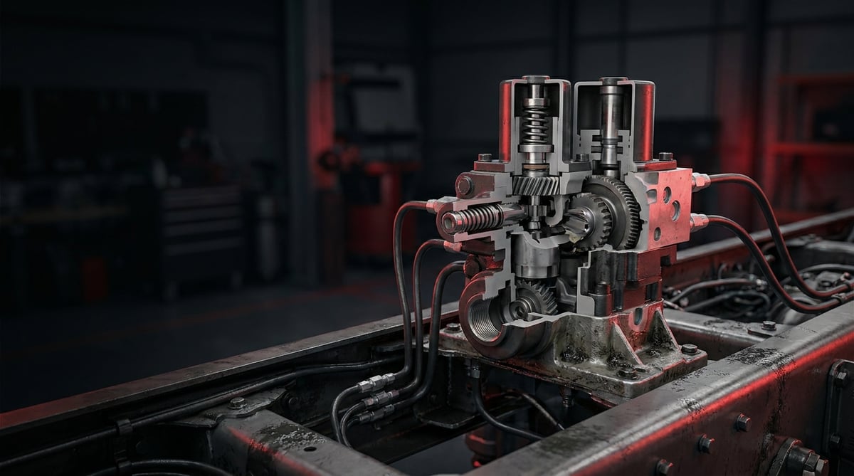
If you have noticed that the rear axle reacts "late" when you press the brake pedal on a heavy commercial vehicle, that there is a timing difference between axles, or that there is a delay when releasing the park brake, one of the first components to inspect is the relay valve. In the pneumatic brake systems of trucks, tractor units, trailers and buses, this small but critical valve recovers the time lost in long air lines and ensures the brakes apply "instantly." Known in German technical documentation as the Relaisventil, it is often also called the "accelerator valve" or "axle valve" in the field. This guide, compiled for heavy commercial vehicle service technicians, covers the operating logic of the relay valve, its common faults, correct replacement steps and field inspection points.
What Is a Relay Valve (+ ABS Relay Valve)? Function and Operating Principle
A relay valve is a pneumatic control valve that, instead of routing the brake signal to a distant axle over a long path, quickly draws and releases air from the large-diameter supply reservoir located right next to the valve, thereby shortening the build-up and release time of the brake pressure.
Its operating principle is based on the logic of a "force amplifier." When the driver presses the brake pedal, the weak, low-flow control signal leaving the main brake valve (foot brake valve), instead of travelling along a long air line, reaches the control (4/control) inlet of the relay valve directly. This control pressure pushes the piston inside the valve downward; the piston in turn allows the full-pressure air coming from the supply reservoir to pass to the brake chambers. When the pedal is released, the control pressure drops, the piston rises, and the air in the brake chambers is rapidly discharged to the atmosphere through the large-diameter exhaust port. In this way, both the apply and release delays are reduced considerably.
The ratio between the control pressure and the output pressure is generally close to 1:1; that is, the valve does not increase the pressure, it increases the flow and the reaction speed. For this reason, the relay valve is a component that determines the "reflexes" of the system.
- Body: Usually cast aluminium alloy; houses the supply, control, delivery and exhaust ports.
- Relay piston / diaphragm: The main element that converts control pressure into mechanical movement.
- Inlet-outlet valve (dual valve): The dual-acting valve group that opens the supply air and directs excess air to the exhaust.
- Springs: Return springs that bring the piston and valve back to the neutral position.
- Exhaust silencer / cover: The port through which the discharged air is expelled and which limits the ingress of dirt and water.
- O-rings and sealing gaskets: Elastomer elements that prevent internal leakage between ports.
Difference Between a Standard Relay Valve and an ABS Relay Valve
A standard relay valve works entirely mechanically-pneumatically; it transfers the control pressure to the outlet rapidly. An ABS relay valve, on the other hand, adds electronic control on top of this function: when wheel lock-up is detected via the electrical signal coming from the EBS/ABS module, the solenoids inside the valve hold, reduce or re-increase the brake pressure on an axle or wheel basis. In other words, the ABS relay valve performs both the acceleration function of the relay valve and the pressure modulation for slip control. Such valves are mostly also referred to as axle modulators in an EBS architecture.
Position in the System and Function
The relay valve is typically mounted on the axle far from the main brake valve — the rear axle on a tractor unit, and near the axle group on the trailer/semi-trailer side — as close as possible to the brake chambers and the supply reservoir. This proximity is the very reason for its existence: the shorter the distance the air has to travel, the faster the response. The spring brake relay valve used in park brake (spring chamber) control and the relay valves in trailer control also apply the same acceleration logic in different circuits.
Typical Application and Matching
| Application / Segment | Example Use | Key Feature |
|---|---|---|
| Tractor unit rear axle (2-axle) | Main brake circuit acceleration | High flow, rapid release |
| Trailer / semi-trailer | Trailer brake control | Predominance option |
| Park / spring brake circuit | Rapid release of spring chamber | Spring brake relay valve type |
| Vehicle equipped with EBS/ABS | Axle modulation + slip control | Solenoid + electronic control |
| Bus / midibus | Compensation of long-chassis line delay | Multi-port distribution |
Fault Symptoms and Diagnosis
Relay valve faults usually start as "the brakes hold, but something feels off." The table below summarises the symptoms most frequently encountered in the field, together with their possible causes and verification methods.
| Symptom | Possible Cause | Check / Verification |
|---|---|---|
| Delayed brake hold, rear axle engages "late" | Control piston stuck or internal valve opens slowly | Use a pressure gauge to measure the timing difference between control and delivery pressure |
| Brake releases late after the pedal is released, wheel overheats | Exhaust port blocked, valve cannot return to the exhaust position | Remove the exhaust silencer and listen to/observe the release speed |
| Continuous air leak from the exhaust port | Inlet valve does not fully close, O-ring worn | Check the exhaust port with soapy foam (with the brake applied and released) |
| Brake imbalance between axles, vehicle pulls under braking | Wrong-type valve, different control ratio or internal leak | Compare the delivery pressures of the two axles simultaneously with pressure gauges |
| ABS warning lamp on / EBS fault | ABS relay valve solenoid or electrical connection fault | Read the modulator fault code and solenoid resistance with a diagnostic tool |
| Brake pressure below target, insufficient braking | Internal leak, restricted supply port or torn diaphragm | With a pressure gauge on the delivery port, compare the pressure at full pedal with the reservoir pressure |
| Irregular operation due to freezing in cold weather | Moisture/water in the system, icing inside the valve | Check the air dryer and reservoir draining; look for the source of moisture |
Pressure and Timing Test with a Pressure Gauge
The most reliable diagnosis is to connect a pressure gauge each to the control inlet and the delivery port and observe whether the two pressures rise simultaneously when the pedal is pressed. In a healthy relay valve, the delivery pressure should follow the control pressure with a very small delay and at almost a 1:1 ratio. A noticeable delay, a low delivery pressure, or a slow drop in the output after the pedal is released points to the valve.
Leak Test
With the brake released, a leak is sought at the exhaust port, and with the brake applied, at the port connections, using soapy foam. A continuous flow of air from the exhaust with the brake applied indicates that the internal valve (inlet valve) does not close fully. A leak from the delivery port to the supply port in the released position points to an internal sealing problem.
ABS/EBS Electronic Diagnosis
On an ABS relay valve, the modulator fault codes are first read with a diagnostic tool, and the solenoid coil resistances and connector pin connections are checked. Even if the mechanical relay section is sound, an electrical interruption can disable the ABS function of the entire axle; for this reason, electronic and pneumatic diagnosis must be carried out together.
Standards and further reading
This subject is governed by the equipment rules for air-braked commercial vehicles. In the United States the federal air brake standard, FMVSS 121 (49 CFR 571.121) defines the reservoirs, protection and timing a compliant system must provide, and Europe applies the equivalent limits of UNECE Regulation No. 13. For further detail, see the illustrated reference guide at airbrakecompressor.com. Always confirm specific figures against the current regulation and the vehicle manufacturer service data.
Outside the United States the equivalent duties sit in national law. In the United Kingdom, regulation 18 of the Road Vehicles (Construction and Use) Regulations 1986 requires every part of the braking system to be maintained in good working order. In Canada, air brake systems fall under the Motor Vehicle Safety Regulations, which contain CMVSS 121.
Replacement / Installation Steps
- Secure the vehicle: Park on level ground, chock the wheels, switch off the engine and turn the ignition to the off position.
- Release the pressure: Drain all air reservoirs of the relevant circuit through their drain valves; confirm on the pressure gauge that the pressure has reset to zero.
- Mark the lines: Before removing them, label or photograph the supply, control, delivery and exhaust lines; incorrect connection is the most common mistake.
- Disconnect the electrical connection (ABS type): On an ABS relay valve, carefully remove the connector from its locking catch; do not damage the pins or the clip.
- Remove the air lines: Loosen the fittings with a suitable wrench; disconnect the hoses and pipes without forcing them, and temporarily cap the port openings to prevent the ingress of dirt.
- Remove the old valve: Undo the mounting bolts/bracket and take the valve out of position; inspect the sealing surface and the condition of the mounting point.
- Clean the mounting surface: Clean the old gasket residue, dirt and rust from the mounting surface; replace the bracket if it is damaged or cracked.
- Position the new valve: Fit the correct-type valve so that the port directions suit the vehicle layout; use a new gasket/O-ring and tighten the bolts progressively to the manufacturer's specified torque.
- Reconnect the lines: According to the labels, connect the supply, control, delivery and exhaust lines to the correct ports; connect the fittings so they seal without overtightening. Make sure the exhaust port faces down/free.
- Connect the electrical connector (ABS type): Push the connector in until it is fully seated and check that the locking catch has engaged.
- Fill and test the system: Start the engine and fill the system to nominal pressure, carry out a leak test on all connections, press and release the pedal to check the hold/release speed and axle balance; on the ABS type, confirm with the diagnostic tool that no fault codes remain.
Points to Watch (Common Mistakes)
- Relying on visual similarity and fitting a valve with a different control ratio — creates axle imbalance.
- Reusing old, hardened O-rings and gaskets — internal leakage and delayed release.
- Tightening the bolts in a single pass, over- or under-torqued — risk of body cracking or leakage.
- Removing lines without releasing the pressure — serious risk of injury.
- Skipping the leak and function test after installation — risk of breakdown on the road or a safety hazard.
- On the ABS type, half-inserting the connector and not locking the catch — fault lamp and loss of function.
- Replacing the valve without solving the air dryer/moisture problem — the new valve is affected in a short time too.
Technical Values and Inspection Points
The values below are typical / general reference ranges for heavy commercial vehicle pneumatic brake systems. They vary according to the vehicle and valve type; for exact values, the OE service manual is authoritative.
| Parameter | Typical Reference Range | Note |
|---|---|---|
| System operating pressure | ~8–12.5 bar (≈116–181 psi) | Varies by vehicle and circuit |
| Control / delivery pressure ratio | ≈ 1:1 (predominance on some types) | Depends on valve type |
| Opening (crack) pressure | In the order of ~0.1–0.4 bar | Depending on the predominance option |
| Permissible internal leakage | In practice "zero" is targeted; measurable leakage = fault | There should be no continuous bubble in the soap test |
| Operating temperature range | Between ~ −40 °C and +80 °C | Elastomer and freezing limit |
| Exhaust release behaviour | Sudden and full release when the pedal is released | Delay = valve/exhaust problem |
Connection torques also vary according to the type and bolt size; the values below are for general reference only.
| Connection | Typical Torque Range | Note |
|---|---|---|
| Body/bracket mounting bolt (M8) | ~20–30 Nm | Tighten progressively and crosswise |
| Body/bracket mounting bolt (M10) | ~40–55 Nm | The OE value is authoritative |
| Air line fitting | According to the manufacturer's specification | Do not overtighten; do not strip the thread |
- Are the control and delivery pressures simultaneous and balanced on the pressure gauge?
- Is the exhaust port free, facing down, and is the release sudden?
- Is the soap test clean on all ports and fittings (no leaks)?
- Are the delivery pressures of the two axles close to each other (balance)?
- On the ABS type, are there any active/memory fault codes in the diagnostic tool?
- Is the exhaust silencer fitted and unclogged?
Maintenance and Service Life
The relay valve is long-lasting together with a correctly functioning air preparation system; its real enemies are moisture, oil and dirt. Feeding the system with clean and dry air significantly extends the life of the valve's internal valve and elastomer elements. In periodic maintenance, the relay valve should be assessed not as a separate component but as a part of the entire pneumatic circuit.
- Replace the air dryer cartridge within the manufacturer's interval; cut off moisture at its source.
- Drain the air reservoirs periodically (especially before winter) and release the accumulated water and oil.
- Keep the exhaust port and silencer clean, open and facing down.
- During periodic brake maintenance, check for leaks and delays around the relay valve.
- On the ABS/EBS type, carry out regular fault code scans with a diagnostic tool.
- Rather than repairing a valve that shows symptoms, prefer to replace it completely, since it is a safety-critical component.
A healthy relay valve generally works trouble-free throughout the vehicle's long service life; however, in damp systems, under heavy operating conditions or on vehicles whose maintenance is neglected, its life is shortened. Timely intervention when symptoms appear both preserves brake safety and prevents the tyre and brake pad wear caused by imbalance between axles.
The relay valve is a safety-critical component that directly determines the reaction speed and axle balance of a heavy commercial vehicle brake system. With correct diagnosis, correct type selection and careful installation, both brake safety and vehicle efficiency are preserved. The VADEN ORIGINAL Relay Valve (+ ABS relay valve) product family is developed for heavy commercial vehicle applications with an OE-compatible port layout, durable sealing elements and a consistent control ratio; by verifying the reference suitable for your vehicle, you can achieve safe and long-lasting braking performance.
Related categories: Relay Valve · Relay Valve · Repair Kit · ABS Solenoid Modulator Valve · Repair Kit
Related technical guides: ABS Wheel Speed Sensor & ECU: Faults, Replacement & Care · Brake Caliper Overhaul Kit: Guide Pins, Boots & Adjuster · Air Processing Unit (APU/EAC): Faults, Replacement & Care · Pressure Limiting Valve: Faults, Replacement & Maintenance · Four-Circuit Protection Valve: Faults, Diagnosis & Replacement
Application and compatibility: Vehicle compatibility catalogue · Engine compatibility catalogue
Main guide: Truck Air Brake Valves Explained: Types, Functions and Failure Symptoms
Tags
Frequently Asked Questions
- What does a relay valve do, and why is it needed?
- It ensures the brake pressure reaches the distant axle faster and is released quickly when the pedal is released. By eliminating the delay in long air lines, it ensures the brakes apply and release instantly.
- What are the symptoms of a relay valve fault?
- The most common ones are: delayed brake hold, the brake releasing late when the pedal is released, a continuous air leak from the exhaust port, brake imbalance between axles, and, on the ABS type, the fault lamp illuminating.
- What is the difference between a relay valve and an ABS relay valve?
- A standard relay valve works entirely pneumatically and only performs the acceleration function. An ABS relay valve, on the other hand, modulates the brake pressure with electronic solenoids to prevent wheel lock-up; it performs both acceleration and slip control.
- Can a relay valve be repaired, or must it be replaced?
- Although a repair kit is available on some types, because it is a critical component for brake safety, complete replacement is generally recommended in the field. If the repair route is taken, the original repair kit and OE procedure must always be used.
- It is leaking air from the exhaust port — is this dangerous?
- A continuous flow of air from the exhaust with the brake applied indicates that the internal valve does not close fully; this leads to both air loss and a drop in brake performance. If confirmed, the valve should be replaced.
- What happens if the wrong relay valve is fitted?
- A valve with a different control ratio or predominance value creates brake imbalance between axles; the vehicle may pull under braking, and brake pad and tyre wear increases. For this reason, the match must always be made with the OE part number suitable for the vehicle.
- Which brands is the relay valve compatible with?
- VADEN relay valve products are designed to be functionally compatible with the OE types of common heavy commercial vehicle pneumatic systems (e.g. Knorr-Bremse, Wabco/ZF, Bendix type/equivalent). For a correct match, the port layout and the OE reference number should be checked.
- Why does the relay valve fail frequently?
- Usually the root cause is not the valve but the moisture, water and dirt in the system. A faulty or saturated air dryer, undrained reservoirs and dirty air wear out the valve's internal valve and gaskets. A replacement made without eliminating the root cause will be short-lived.
- How can I confirm with a pressure gauge that the relay valve is at fault?
- Connect one pressure gauge to the control inlet and another to the delivery port, then press the pedal and watch whether both pressures rise at the same time. On a healthy valve the delivery pressure follows the control pressure with a very small delay, at almost a 1:1 ratio. A noticeable delay, a low delivery pressure, or a slow drop after the pedal is released points to the valve.
- What is the most common mistake when replacing a relay valve?
- Mixing up the ports. Connecting the supply, control and delivery lines to the wrong ports is the most common and most dangerous error; running the control line into the supply port leaves the brake working incorrectly or not at all. Label or photograph every line before removal and confirm the port directions after fitting. Also check that the exhaust port faces down and free.
Related Articles

EBS Modulator: Faults, Diagnosis, Replacement Guide
Technical guide to the EBS modulator on trucks and trailers: how it works, fault symptoms, diagnosis, replacement steps, torque values and maintenance tips.

ABS Brake System: How It Works, Warning Light and Faults
Learn how the ABS brake system works on heavy trucks, why the warning light comes on, how to diagnose sensor faults, and the correct replacement steps.
Brake Chamber, Diaphragm & Hose: Faults, Replacement, Care
Learn how to spot a leaking brake chamber, measure push rod stroke, cage the power spring safely and replace the unit and hose without risk on heavy trucks.


