Compressor Valve & Unloader: Fault, Replacement & Care Guide
Low air pressure on a truck, or a compressor that never cuts out, usually means worn intake and discharge reed valves or a stuck unloader: how to fix it.
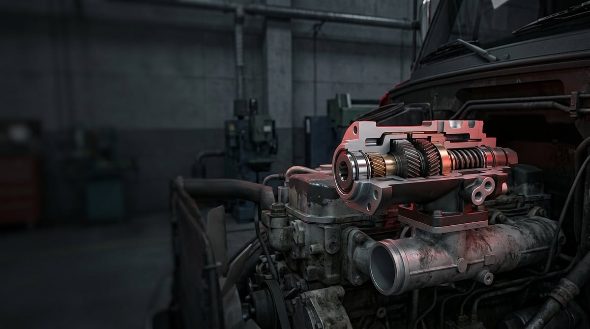
If air pressure stays low on a heavy commercial vehicle, if the compressor runs continuously and never cuts out, or if you hear a whistle-like leak from the intake area when the engine drops to idle, one of the first places to check is the compressor's valve and unloader assembly. In the field, many drivers and technicians blame the problem directly on the compressor or the air dryer; yet the intake and discharge valves together with the unloader mechanism form the critical intermediate component that determines "when the compressor delivers air" and "when it runs unloaded." This guide explains this assembly's function, its typical failures, the diagnostic method, the replacement steps and the maintenance intervals in language you can apply directly in the field.
This document was prepared by the VADEN technical team, drawing on field experience with heavy commercial vehicle air brake systems and OE manufacturer documentation. The pressure, torque and temperature ranges given here are typical/general reference values; for exact figures, always refer to the current OE service manual for the vehicle and the compressor. Last updated: September 2026.
Heavy commercial vehicle air brake systems are designed within the framework of ECE R13 (UN/EU braking regulation) and ISO 611.What Is the Compressor Valve & Unloader Assembly? Function and Operating Principle
The compressor valve & unloader assembly is the intermediate component that covers the air compressor's intake and discharge valves together with the unloader mechanism, controlling whether the compressor delivers air based on system pressure.
On a heavy commercial vehicle the compressor is driven continuously by the engine (via gear, belt or direct drive); however, it does not always deliver air to the system. When the air tank pressure reaches the upper limit set by the pressure regulator (governor), the unloader mechanism engages and the compressor begins to run "unloaded" (no load). When the pressure drops to the lower limit, the unloading is disengaged and the compressor starts delivering air again. This cycle prevents both unnecessary energy consumption and excessive heat build-up.
The intake and discharge valves ensure air moves in a single direction on each stroke: the intake valve draws air into the cylinder, while the discharge valve sends the compressed air to the dryer/tank and prevents backflow. Because the valve reeds (leaves) operate at high frequency with very small movements, they are the parts most prone to wear and fatigue.
- Intake valve (reed/leaf): Controls the intake of air into the cylinder.
- Discharge valve (reed/leaf): Delivers the compressed air and prevents backflow.
- Valve plate / valve seating surface: The surface on which the reeds seat, determining the seal.
- Unloader piston/pins: Hold the intake valve open on the governor signal to unload the compressor.
- Springs and seals/O-rings: For valve return and sealing.
- Gasket set: Seals between the cylinder head and the block.
How Does Unloading Take Place?
The governor continuously monitors the tank pressure. When the upper cut-out pressure is reached (typically around the 12–13 bar range, varying by system), the governor sends control air to the unloader piston. The piston locks the intake valve in the open position; the compressor can therefore no longer compress air and runs unloaded. When the pressure drops to the lower cut-in value, the governor exhausts the air and the compressor is loaded again.
The Role of the Intake and Discharge Valves
If the valve assembly is not sound, the compressor efficiency drops even when the unloader works flawlessly. A leaking discharge valve allows the delivered air to flow back into the cylinder and causes the compressor to run continuously. This in turn triggers both oil carry-over and overheating.
Differences by Compressor Type
The valve and unloader layout differs between single-cylinder, twin-cylinder, water-cooled and air-cooled compressors. The table below broadly compares the common compressor types with the characteristics of the assembly.
| Compressor Type / Application | Typical Drive | Cooling | Unloader Arrangement | Common Use |
|---|---|---|---|---|
| Single-cylinder (low flow) | Gear / belt | Air or water | Single intake valve unloading | Mid-segment truck, bus auxiliary |
| Twin-cylinder (high flow) | Gear / direct | Usually water-cooled | Twin intake valve / piston unloading | Tractor unit, heavy truck, bus |
| Water-cooled high performance | Gear | Engine coolant | Piston + governor controlled | Long-haul tractor units, heavy crane |
| Energy-saving (ESS/intermittent) | Gear | Water | Electronic/pneumatic unloading | New-generation EURO 6 vehicles |
Part number verification: Compressor valve and unloader sets must match the compressor brand, model and cylinder count exactly. Before ordering, verify by comparing the OE number on the compressor (e.g. Knorr-Bremse, Wabco, Bosch equivalent/type compressors) and, where available, the vehicle chassis/engine code against the VADEN product family. Visual similarity is not enough; the reed dimensions and the seating surface geometry are critical.
Failure Symptoms and Diagnosis
Valve and unloader failures are often interpreted as "the compressor is broken"; however, if the symptoms are read carefully, the faulty assembly can be distinguished. The table below matches the symptoms most frequently encountered in the field with their probable causes and check methods.
| Symptom | Probable Cause | Check / Verification |
|---|---|---|
| Compressor runs continuously, does not cut out | Leaking discharge valve or unloader sticking; system leak | Measure tank fill time; watch the governor cut-out pressure on a gauge; look for a system leak with soapy water |
| Pressure rises slowly / fills late | Worn intake-discharge reeds, low compressor efficiency | Measure the fill time from 0 to working pressure with a stopwatch and compare with the OE value |
| Air leak sound from the intake/head area | Damaged valve plate gasket or leaking intake valve | Listen around the head and the intake inlet at idle; check for bubbles with soapy water |
| Excessive oil in the system / oil carry-over in the dryer | Oil vapour carry-over due to heat, continuous loaded operation | Check the dryer cartridge and air line for oil traces; observe the compressor outlet temperature |
| Compressor does not go unloaded (does not shed load) | Unloader piston sticking, no governor signal arriving | Check the governor outlet line and the unloader control air from the test port |
| Compressor does not load (always unloaded) | Unloader piston stuck open, governor signalling continuously | Check the governor setting/output; verify the free movement of the unloader piston |
| Abnormal ticking / knocking noise | Broken reed, loose valve plate, damaged spring | Remove the compressor and visually inspect the valve plate |
Fill Time Test
This is one of the most reliable field tests. After the tanks are drained, with the engine running at a steady speed, the time for the pressure to reach a certain value (e.g. from zero to working pressure) is measured. If the time is noticeably longer than the OE reference, the valve efficiency has dropped. The exact time value depends on the compressor flow and the tank volume; the service manual is authoritative.
Cut-out and Cut-in Check
The governor's cut-out and re-load (cut-in) pressures are monitored on a gauge. When the cut-out pressure is reached, confirm that the compressor goes unloaded (the intake sound stops). If it does not go unloaded, focus on the unloader or the governor side.
Leak Isolation
Continuous operation is not always valve-related; system leaks give the same symptom. First narrow down the leak by isolating the air lines, the dryer and the valves. Do not remove the compressor assembly before confirming the source.
Standards and further reading
This subject is governed by the equipment rules for air-braked commercial vehicles. In the United States the federal air brake standard, FMVSS 121 (49 CFR 571.121) defines the reservoirs, protection and timing a compliant system must provide, and Europe applies the equivalent limits of UNECE Regulation No. 13. For further detail, see the illustrated reference guide at airbrakecompressor.com. Always confirm specific figures against the current regulation and the vehicle manufacturer service data.
Readers outside the United States should work from their own national framework: in the United Kingdom the braking system must be maintained under regulation 18 of the Road Vehicles (Construction and Use) Regulations 1986, and in India the governing rules are published by the Ministry of Road Transport and Highways.
Replacement / Installation Steps
Personal protective equipment and safety: Before starting work, stop the engine, chock the wheels so the vehicle cannot move, and fully release the pressure in the air tanks. A pressurized system causes serious injury. The compressor may be hot; wait for it to cool. Use protective goggles and gloves. On water-cooled compressors, safely drain the coolant line as well.
- Release the pressure: Drain all air tanks through the drain valves and confirm zero pressure on a gauge.
- Mark the connections: Before disconnecting the air, governor control, coolant and oil lines, photograph and label them; this prevents incorrect assembly.
- Disconnect the lines: Carefully separate the discharge line, intake line, unloader control line and (if present) the water/oil lines; cap the open ends to prevent dirt ingress.
- Remove the cylinder head: Loosen the head bolts in a cross pattern and in stages; lift the head without forcing it.
- Remove the valve plate: Take out the valve plate, the reeds and the old gaskets. Visually inspect the seating surfaces and the unloader piston.
- Clean the surfaces: Clean off the old gasket residue on the block and head sealing surfaces without scratching the surface. Check the surface flatness.
- Renew with the new set: Fit the new valve reeds, plate, unloader elements and gasket set, paying attention to their orientation. The reed orientation and seating are one-way only.
- Position the gaskets correctly: Assemble the gasket set in the sequence specified by the manufacturer; do not apply unnecessary sealant on the gasket (unless specified).
- Torque the head: Tighten the head bolts in a cross pattern, in stages and to the OE torque value. Do not apply full torque in a single pass.
- Connect the lines: Reconnect all air, control, water and oil lines according to their labels; check the fitting seals.
- Test: Start the engine, fill the system; check the fill time, the cut-out/cut-in pressures and for leaks. Test around the head with soapy water.
Points to Watch (Common Mistakes)
The most critical mistake: Starting the removal work without fully releasing the pressure. The pressure remaining in the system both creates a safety risk and causes parts to fly off. The second critical mistake is fitting the valve reeds the wrong way round; a reversed reed leaves the compressor completely inefficient.
- Assembling the gasket set incompletely or in the wrong sequence — causes an air/oil leak.
- Tightening the head bolts in a single pass — warps the plate and crushes the gasket; cross-pattern, staged torquing is essential.
- Fitting a new gasket without cleaning the old seating surfaces — the seal is not achieved.
- Overlooking the real cause of the drop in compressor efficiency (dryer, governor, system leak) and simply replacing the valve.
- Using the wrong part number / a set for a different cylinder count.
- Neglecting the cleanliness of the oil and intake line — dirt is carried into the new valve.
- Replacing only the reeds without checking the unloader piston and its pins — the problem recurs.
On the first run after replacement, note the compressor outlet temperature and the fill time. Recording these values in the service log provides a valuable reference for comparison at the next maintenance.
Technical Values and Check Points
The values below are typical/general reference ranges for heavy commercial vehicle air compressors. They vary by compressor brand, model and vehicle type; for exact figures, the OE service manual is authoritative.
| Parameter | Typical Reference Range | Note |
|---|---|---|
| Governor cut-out pressure | ~12.0–13.0 bar (≈174–189 psi) | Varies by system and vehicle |
| Governor cut-in pressure | ~10.0–11.5 bar (≈145–167 psi) | A difference of ~1.5–2 bar from the cut-out is typical |
| Working pressure band | ~8–12 bar | Brake system operating range |
| Compressor outlet temperature (normal) | Generally below ~180 °C | Continuously high temperature risks oil carry-over |
| Intake air pre-filter condition | Clean / unclogged | A clogged filter reduces efficiency |
| Fill time (tank+system) | Per OE reference | Marked increase = low valve efficiency |
The torque for the head and valve plate bolts varies by compressor model. The table below is only a general reference; the exact torque value must be confirmed against the compressor manufacturer's instructions.
| Connection | Typical Torque Range (general reference) | Application Note |
|---|---|---|
| Cylinder head bolts | ~20–35 Nm | Cross-pattern, staged tightening |
| Valve plate / intermediate bolts | ~10–20 Nm | Varies by model |
| Line fittings | Manufacturer value | Over-tightening damages the thread/fitting |
Always apply torque values with a calibrated torque wrench. Tightening by "feel" is the most common mistake causing plate warping and recurring gasket leaks on twin-cylinder compressors.
Field check points:
- Verify the governor cut-out and cut-in pressures with a gauge.
- Confirm from the intake sound that the compressor goes unloaded at the moment of cut-out.
- Check around the head and the intake inlet for leaks with soapy water.
- Measure the fill time and compare it with the OE reference.
- Look for oil carry-over in the dryer cartridge and the lines.
- On water-cooled models, check the coolant line flow and for leaks.
Maintenance and Service Life
The service life of the valve and unloader assembly depends on the air quality, the operating temperature, oil carry-over and the general maintenance of the system. The compressor should never be considered on its own; it must be treated as a system together with the dryer, the governor and the air lines. On a vehicle whose dryer is not doing its job, the valves wear out far faster.
- Periodically check the intake air pre-filter and keep it clean; dirty air accelerates valve wear.
- Replace the dryer cartridge at the interval recommended by the manufacturer; oil and moisture carry-over ruins the valves.
- Regularly drain water from the tank drain valves; moisture accumulating in the system creates corrosion.
- Measure the fill time periodically to catch efficiency loss early.
- Investigate the cause of excessive and continuously high compressor temperature (continuous loaded operation, leak).
- Prefer to renew the valve assembly as a complete set rather than individually; the reed, plate, unloader and gasket should be changed together.
On vehicles with regular air system maintenance, the valve and unloader assembly runs trouble-free for a long time; on neglected systems, early failure, a continuously running compressor and increased fuel consumption are inevitable. When the symptoms appear, renewing the assembly as a complete unit is both safer and more economical than trying parts one by one.
The VADEN ORIGINAL Compressor Valve & Unloader product family brings together reeds, valve plates, unloader elements and gasket sets matched to OE geometry for heavy commercial vehicle air compressors. Using a complete set matched to the correct part number prevents early failure, restores compressor efficiency and provides a safe, long-lasting solution in the field. To choose the set for your needs, make your selection by comparing your compressor's OE number against the VADEN product family.
Related categories: Valve Kit · Unloader Kit · Safety Valve · Governor Valve
Related technical guides: Compressor Piston-Ring & Connecting Rod: Repair Guide · Truck Air Compressor Overhaul Kit: Head, Valve Plate, Gasket · Compressor Crankshaft & Drive Assembly: Failure & Replacement Guide · Compressor Cooling Plate & Water Cooling: Faults, Repair & Care
Application and compatibility: Vehicle compatibility catalogue · Engine compatibility catalogue
Main guide: Air Brake Compressor: Faults, Replacement & Maintenance Guide
Tags
Frequently Asked Questions
- The compressor runs continuously and does not cut out — is the valve the problem?
- It may be, but the valve is not the only possible cause. A leaking discharge valve or a stuck unloader produces this symptom; however, a system leak and a clogged dryer produce the same result. First measure the fill time and perform leak isolation; do not remove the assembly before confirming the source.
- What does the unloader do?
- The unloader mechanism, when the tank pressure reaches the upper limit, runs the compressor unloaded to prevent unnecessary pressure generation, energy consumption and heat build-up. On the governor signal, it holds the intake valve open and prevents the compressor from compressing the air.
- Can the intake-discharge valve be repaired by replacing the reeds only?
- In some cases replacing the reeds is enough; however, if the valve plate seating surface is damaged or the unloader elements are worn, replacing only the reeds solves the problem only temporarily. The soundest approach is to renew the valve and unloader assembly as a complete set.
- Does a valve failure require complete replacement of the compressor?
- Usually no. The valve and unloader assembly can be renewed separately if the compressor body is sound. However, if there is serious wear, scoring or ring damage on the cylinder/piston surface, an overhaul or replacement of the compressor comes onto the agenda.
- What torque should I use after replacement?
- The head and plate bolts are tightened to different torques depending on the compressor model; the general reference ranges are given in this guide, but for the exact value the OE service manual is authoritative. Always tighten with a calibrated torque wrench, in a cross pattern and in stages.
- Is there a relationship between the dryer and valve failure?
- Yes, there is a direct relationship. A dryer not doing its job leads to moisture and oil being carried into the valve assembly; this causes early deterioration of the reeds and the seating surfaces. When replacing the valve, always check the condition of the dryer as well.
- The compressor gets very hot — could it be valve-related?
- It could. A leaking discharge valve or continuous loaded operation (the unloader does not go unloaded) causes the compressor to run more than necessary and overheat. Excessive temperature in turn triggers oil carry-over, creating a vicious cycle.
- Is the valve & unloader set independent of the compressor brand?
- No. The set is tied exactly to the compressor brand, model and cylinder count. The valve geometries of Knorr-Bremse, Wabco or Bosch type/equivalent compressors differ. Verification against the OE number before ordering is essential.
- How can I tell in the field that valve efficiency has dropped?
- Use the fill time test. Drain the tanks, run the engine at a steady speed and measure how long the pressure takes to climb from zero to working pressure; if it is noticeably longer than the OE reference, valve efficiency has fallen. The exact figure depends on compressor flow and tank volume, so take it from the service manual. Pair it with a cut-out check: if the compressor does not go unloaded, look at the unloader or governor.
- What safety steps are essential before removing the valve assembly?
- Stop the engine, chock the wheels and drain every air tank through its drain valve until the gauge confirms zero pressure. Starting the removal with pressure still in the system is the most critical mistake on this job; it can throw parts off and cause serious injury. Let the compressor cool before touching it, wear goggles and gloves, and on water-cooled units safely drain the coolant line as well.
Related Articles
Compressor Connection Hardware: Faults, Replacement, Care
How truck air compressor adapters, bolts, plugs and hoses fail, how to diagnose leaks and blockages, replace them correctly and extend service life.
Compressor Repair and Gasket Kit: Faults, Replacement, Care
Diagnosing air compressor gasket failure on trucks: choosing the right repair kit scope, preparing surfaces, torquing correctly and extending seal life.
Compressor Cooling Plate & Water Cooling: Faults, Repair & Care
Diagnose, replace and maintain the heavy-truck air compressor cooling plate and water cooling: symptoms, internal-leak testing, torque values and FAQ.


