Air Processing Unit (APU/EAC): Faults, Replacement & Care
Air processing unit (APU/EAC) guide for trucks: how it works, fault symptoms, pressure diagnosis, replacement steps, torque values and cartridge maintenance.
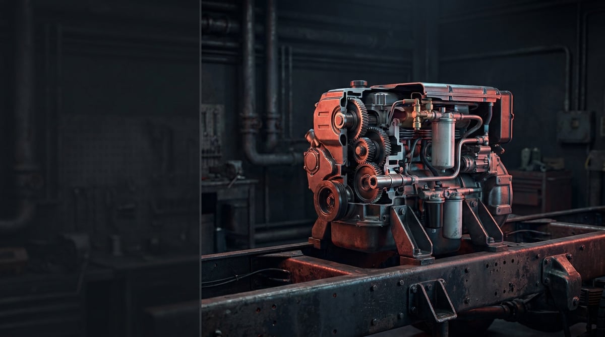
If the compressor refuses to fall silent for minutes after you turn the key in the morning, if the unit's exhaust keeps hissing without a break, or if a dirty, oily fluid pours out when you drain the reservoirs, the problem is usually not the compressor — it is the vehicle's air treatment unit. This unit looks small, but it is the single gateway feeding the brake, parking, suspension and transmission circuits alike. Block that gateway and braking performance drops, lines freeze in winter, and you end up waiting at the roadside. This guide explains, in workshop language, what the air processing unit (APU/EAC) does, which symptom points to which fault, how it is diagnosed and replaced, and how to extend its service life.
E-E-A-T note: This document was prepared by the VADEN technical team, which works on heavy commercial vehicle air and brake systems. The pressure, torque and interval values given here are general reference figures; for exact values such as cut-out pressure, circuit opening pressures and tightening torque, always follow the vehicle manufacturer's current OE service manual. Last updated: September 2026.
Heavy commercial vehicle air brake systems are designed within the framework of ECE R13 (UN/EU braking regulation) and ISO 611.What Is an Air Processing Unit (APU/EAC)? Function and Operating Principle
The air processing unit (APU / EAC) is an integrated module that dries and cleans the hot, moist, oil-laden air coming from the compressor, limits system pressure, and distributes the treated air to the brake and auxiliary circuits according to a priority order — combining the air dryer, the pressure regulator and the multi-circuit protection valve in a single housing.
Its operating principle has two phases. In the charging phase, the air delivered by the compressor enters the unit; the desiccant granules inside the dryer cartridge capture the water vapour in the air, while the oil separator layer traps oil droplets. The dry air is routed through the protection valve first to the brake circuits (circuits 1 and 2), and once those are charged, to the parking and auxiliary circuits (circuits 3 and 4). When system pressure reaches the cut-out value, the pressure regulator unloads the compressor. In the regeneration phase, the unit passes part of the dry air from the regeneration reservoir back through the cartridge in the reverse direction and blows the moisture out; the short "pssht" sound you hear from the exhaust is this, and it is normal.
The unit typically contains the following components:
- Dryer cartridge (desiccant/oil separator): A screw-on consumable part that traps moisture and oil in the air. This is the only true "filter" in the vehicle's air system.
- Pressure regulator (governor): The valve group that sets the cut-out and cut-in pressures and unloads the compressor.
- Multi-circuit protection valve: The valve package that protects the remaining circuits when one circuit leaks, establishing a priority order through its opening/closing pressures.
- Regeneration valve and purge outlet: The line that cleans the cartridge with reverse airflow and expels condensed water.
- Safety valve: The mechanical fuse that protects the system from overpressure if the regulator fails.
- Heater element and thermostat: Usually a 24 V electrical component that prevents the purge outlet from freezing in winter.
- Electronic control (only on EAC/electronic APUs): The board with pressure sensors and solenoid valves that communicates with the vehicle ECU over CAN.
The difference between a mechanical APU and an electronic EAC
In mechanical units all decision logic comes down to springs and pistons: at a given pressure the compressor is unloaded, and when pressure drops to another value it starts pumping again. In electronic units (Knorr-Bremse EAC type or Wabco/ZF electronic APU type) the decision is made by an ECU reading pressure sensors. This allows the compressor to be engaged according to engine load (charge on downhill runs, unload under acceleration), saves fuel, and makes faults visible as fault codes. On the other hand, diagnosing an electronic unit requires a diagnostic tool as well as a pressure gauge and a multimeter; on some vehicles, parameter writing after replacement is mandatory.
Its place in the system: why the "single gateway"?
Air leaving the compressor enters the system only through this unit. If the unit becomes blocked, it is not just the brakes that suffer; air suspension bellows, transmission actuators, cab suspension, the trailer line and the PTO — everything that uses air is affected. And if it fails to dry the air sufficiently, moisture and oil spread to every valve, air bellow and EBS modulator. That is why the "I skipped the dryer cartridge, I'll look at it later" approach is the seed of far more expensive valve failures down the road.
Why this drying stage matters so much for the whole circuit is explored separately in our article the air dryer: the hidden hero of heavy vehicle air systems.
Which vehicles use which type?
The general trend is this: on older-generation tractor units and many truck/bus applications, the separate layout (individual dryer + individual regulator + individual protection valve) is common. On new-generation tractor units, the integrated APU/EAC is standard. Confirming the type on your vehicle from the OE number on the housing and the connector pin count is always safer than guessing from a catalogue.
| Feature | Separate Layout (classic) | Mechanical Integrated APU | Electronic APU / EAC |
|---|---|---|---|
| Control logic | Mechanical regulator | Mechanical regulator (integrated into housing) | ECU + pressure sensor + solenoid |
| Electrical connection | Usually none (heater if fitted) | Heater supply | Multi-pin connector + CAN |
| Does it generate fault codes? | No | No | Yes (DTCs can be read) |
| Diagnostic method | Pressure gauge + ear + leak test | Pressure gauge + leak test | Pressure gauge + diagnostics + live data |
| Coding after replacement | Not required | Not required | Required on some vehicles |
| Repair flexibility | Parts can be replaced individually | Cartridge + repair kit | Cartridge + repair kit; board usually complete unit |
| Typical OE context | Knorr / Wabco type separate groups | Wabco APU type integrated housing | Knorr EAC / ZF-Wabco electronic APU type |
Part number verification: Air processing units look very much alike from the outside; however, cut-out pressure, circuit opening values, port threads, connector pin layout and software level may differ. Before ordering, always verify the OE number on the unit housing, the vehicle chassis number and the connector type together. "It fits the same vehicle" is not sufficient on its own; a unit with the wrong pressure setting quietly makes the brake system unsafe.
Fault Symptoms and Diagnosis
Air processing unit faults rarely "blow up" all at once; they usually announce themselves through small symptoms that grow over weeks. The table below matches the symptoms most frequently seen in the field with their likely causes.
| Symptom | Likely Cause | Check / Verification |
|---|---|---|
| Compressor never stops, pressure never reaches the cut-out value | Blocked cartridge, faulty regulator, major system leak, weak compressor | Measure charging time with a pressure gauge; compare unit inlet pressure with reservoir pressure; look for leaks with soapy water |
| Air continuously escapes from the exhaust/purge outlet | Regeneration valve leaking, o-ring fatigued, cartridge seal not sealing | Listen at the purge port with the engine off; apply soap foam; remove and refit the cartridge and try again |
| A water/oil mixture comes out when draining the reservoirs | Cartridge saturated or past its service life, compressor passing oil | Check the cartridge replacement date; inspect for oil build-up in the compressor outlet line |
| Pressure falls, vehicle found empty after overnight parking | Protection valve check valves leaking, internal unit leak, loose line fitting | Leave the reservoirs charged and record the overnight pressure drop; isolate the circuits one by one |
| Brake pressure builds but the parking/suspension circuit charges late or not at all | Circuit 3/4 opening pressure not reached, protection valve faulty | Measure each circuit separately with a pressure gauge at the test ports; observe the charging sequence |
| Pressure will not build on winter mornings, recovers towards midday | Purge line frozen, heater element or thermostat faulty | Measure heater resistance and supply voltage; check the fuse/socket |
| Air escaping from the safety valve, pressure excessively high | Regulator cannot unload the compressor, unloader line blocked | Read the cut-out pressure with a gauge; check the control line at the regulator outlet |
| Air system/EAC warning or fault code on the dashboard | Pressure sensor, solenoid or ECU fault; supply/CAN problem | Read DTCs with a diagnostic tool; compare sensor pressure in live data against a real gauge |
Pressure measurement: the backbone of diagnosis
In air processing unit diagnosis, the only valid evidence is the pressure gauge. The dashboard indicator and the on-screen data depend on the sensor; if the sensor reads wrong, you head in the wrong direction. The correct method: connect a real pressure gauge to the vehicle's test ports and record the cut-out pressure as the compressor charges, the cut-in pressure once air is consumed, and the charging order of the circuits. On an electronic unit, if the difference between the live data value and the gauge clearly exceeds 0.3–0.5 bar, the sensor is suspect.
Leak or blockage? A practical way to tell them apart
A compressor that never stops is the shared symptom of two different stories. If the system charges quickly but the pressure stalls at some point, the cause is usually a leak. If the system charges slowly and with difficulty, the cause is usually a blockage or a weak compressor. To make the distinction clear, measure the pressure at the unit inlet and the reservoir pressure at the same time: if the difference between them grows noticeably, the cartridge/unit is blocked.
Ask the foam about the leak, not your ears
It is impossible to hear small leaks over engine noise. With the reservoirs charged and the engine off, sweep the unit housing, all ports and the purge outlet with a soapy water spray. The "overnight test" is also revealing: record the pressure in the evening and read it again in the morning. If there is a clear drop, narrow down the source by isolating the circuits one at a time.
Standards and further reading
This subject is governed by the equipment rules for air-braked commercial vehicles. In the United States the federal air brake standard, FMVSS 121 (49 CFR 571.121) defines the reservoirs, protection and timing a compliant system must provide, and Europe applies the equivalent limits of UNECE Regulation No. 13. For further detail, see the on-road braking performance requirement in 49 CFR 393.52. Always confirm specific figures against the current regulation and the vehicle manufacturer service data.
Readers outside the United States should work from their own national framework: in the United Kingdom the braking system must be maintained under regulation 18 of the Road Vehicles (Construction and Use) Regulations 1986, and in India the governing rules are published by the Ministry of Road Transport and Highways.
Replacement / Installation Steps
Safety and PPE: The air system is under pressure; trapped air can cause serious injury. Before starting work, put on safety glasses and work gloves, chock the vehicle on level ground, switch off the ignition, disconnect the battery isolator and drain all air reservoirs completely. The parking brake is spring-applied: when air is released the parking brakes engage, but if the trailer has been uncoupled or the system is mechanically locked, always use chocks. On a hot engine, the unit and lines can burn.
- Confirm the fault: Base the decision to replace on pressure gauge measurements, a leak test and (if available) fault codes. In most cases it is not the unit but the cartridge or a single o-ring that gets renewed.
- Drain the system completely: Open the drain valves on all reservoirs and see zero on the gauge. Do not forget the regeneration reservoir on the unit either.
- Cut the power and disconnect the connector: Disconnect the battery isolator and remove the heater and (if fitted) ECU connector without damaging its lock. Check the connector pins for corrosion.
- Mark the lines: Before removal, number every air line with colour/tags or photograph them. One mixed-up line can feed the parking circuit instead of the brake circuit.
- Remove the lines and the unit: Loosen the fittings with a suitable spanner without straining the housing. Take care not to overtighten and crack the fittings of plastic lines; then undo the housing mounting bolts.
- Clean the mounting face and the lines: Clean the bracket the unit sits on. Blow out moisture, rust and oil deposits inside the lines with compressed air; a dirty line kills a new unit in no time.
- Compare the new unit: Place the old and new parts side by side; the port count, port threads, mounting hole spacing, connector type and OE number must match. If they do not, do not fit it — verify the correct reference.
- Mount the unit: Start the bolts by hand, align the housing, then tighten them in a cross pattern to the torque value in the manual. Do not try to force the housing into alignment.
- Fit the cartridge: Moisten the new cartridge's seal with a thin film of clean oil, turn it by hand until the seal makes contact, then tighten it by the additional turn stated in the manufacturer's instructions (usually around half a turn). Overtightening with a pipe wrench crushes the seal and causes leaks.
- Connect the lines and the connector: Refit every line according to your markings, tighten the fittings to the manual torque, and seat the connector until it locks.
- Charge, test and code if required: Reconnect the battery and charge the system; verify the cut-out/cut-in pressures and the circuit charging order with a pressure gauge, and check all connections with foam. On an electronic unit, clear the fault codes, perform parameter writing if required, and monitor pressure behaviour on a short road test.
Points to Watch (Common Mistakes)
The most critical mistake — dismantling without draining the reservoirs: Loosening a fitting on a charged system can send the line whipping around and cause visible injury. Do not touch any connection until you see zero on the gauge.
The second critical mistake — tightening the cartridge with a pipe wrench: Dryer cartridges are fitted hand-tight plus the specified additional turn. An overtightened cartridge has its seal crushed, the thread in the unit housing gets damaged, and the cartridge becomes impossible to remove at the next replacement.
- Neglecting the compressor: A compressor passing oil saturates a new cartridge within a few thousand kilometres. If you see plenty of oil in the cartridge, assess the compressor first.
- Mixing up the lines: Swapping circuits 1/2 with 3/4 destroys brake priority and disables the safety logic in the event of a leak.
- Trying to adjust the pressure setting "by hand": The regulator's cut-out value is determined for the vehicle's entire air system. Raising it arbitrarily strains the safety valve, the air bellows and the compressor.
- Using a low-quality cartridge: Desiccant quality and oil separation performance are invisible to the eye, but they present the bill months later at the valves and modulators.
- Forgetting the heater: Finishing the job without plugging in the connector causes no trouble all summer; at the first frost, the vehicle cannot set off.
- Connecting a dirty line to a new unit: Rust and oil accumulated in the old lines get carried into the new unit's valves.
- Not testing after replacement: Do not hand the vehicle over without verifying the pressure values with a gauge; a cleared fault code does not prove that the system works correctly.
Technical Values and Inspection Points
The values below are general references commonly encountered in heavy commercial vehicle applications. They vary significantly by vehicle, manufacturer and system type; for exact values, the OE service manual is authoritative.
| Parameter | Typical / General Reference | Note |
|---|---|---|
| Cut-out pressure | ~ 12.0 – 13.0 bar (≈ 175 – 190 psi) | Lower on 10 bar systems; consult the manual |
| Cut-in pressure | ~ 0.8 – 1.5 bar below the cut-out value | If the gap is too small, the compressor cycles frequently |
| Safety valve opening pressure | Set clearly above the cut-out pressure; the exact value is in the vehicle manual | If it opens, the regulator/unloader is suspect |
| Brake circuit (1 and 2) opening pressure | ~ 7.5 – 8.5 bar | Circuit priority: the brakes charge first |
| Brake circuit closing (cut-off) pressure | ~ 6.5 – 7.5 bar | Protects the other circuits in the event of a leak |
| Parking / auxiliary circuit (3 and 4) opening pressure | After the brake circuits, at lower priority | The value varies by type; the sequence must be correct |
| Regeneration air consumption | ~ 10 – 25% of the air produced | Continuous purging is not normal |
| Heater element | 24 V, ~ 35 – 110 W range | Thermostat-controlled; engages in cold weather |
| Operating temperature range | ~ -40 °C … +80 °C | The purge outlet is the point most prone to freezing |
| Charging time from zero to full pressure | In the order of a few minutes at above-idle speed | A noticeable increase = blockage or leak |
| Overnight pressure drop | Must stay below the limit value in the manual | A noticeable drop = leak; isolate the circuits |
General reference ranges for tightening torques:
| Connection | Typical / General Reference | Note |
|---|---|---|
| Dryer cartridge | Hand-tight to seal contact + ~ 1/3 – 1/2 turn | Not with a wrench; the instruction on the cartridge is authoritative |
| Unit housing mounting bolts (M8) | ~ 20 – 30 Nm | Tighten in a cross pattern |
| Unit housing mounting bolts (M10) | ~ 40 – 55 Nm | Do not force the bracket alignment |
| Air line fittings (small diameter) | ~ 20 – 35 Nm | Overtightening cracks plastic line fittings |
| Air line fittings (large diameter) | ~ 35 – 50 Nm | Varies by o-ring / seal type |
| Heater element | ~ 8 – 15 Nm | Do not strain the housing thread |
| Pressure sensor | ~ 15 – 25 Nm | Fit the seal dry and clean |
Field tip: When you change the cartridge, write the replacement date and mileage on it with a permanent marker. At the next service the "when was it changed?" debate is over; in fleet maintenance, this single habit prevents a great many unnecessary unit replacements.
Routine inspection points:
- The fluid coming from the reservoir drain valve: a clear drop is normal; a water/oil mixture is a cartridge warning.
- Purge outlet: a short discharge at the moment of cut-out is normal, a continuous air leak is a fault.
- Compressor duty cycle: continuous charging tells the system "leak or blockage".
- Housing and area around the ports: oil traces, rust, cracks, broken bracket.
- Connector and cable: green corrosion, loose lock, chafing wear.
- Heater: supply and resistance check before winter.
- On an electronic unit: fault code history and agreement between the live pressure data and the gauge.
Maintenance and Service Life
The air processing unit itself is a long-life module; the real consumable is the dryer cartridge. Cartridge life must be planned according to operating conditions: a humid climate, urban stop-and-go running, heavy air bellow use and an aged compressor saturate a cartridge rapidly; on long-haul work and in dry climates, life is extended. General industry practice is to change the cartridge once a year or at the mileage interval specified by the OE; for the final interval, the vehicle manufacturer's maintenance schedule is authoritative.
- Change the cartridge on schedule: It is a cheap consumable; the price of delay is valve and modulator failure.
- Drain the reservoirs regularly: The habit of weekly draining gives you a free report on the state of the cartridge.
- Assess the compressor at the same time: Changing the cartridge without repairing an oil-passing compressor is not a lasting solution.
- Prepare before winter: Check the heater circuit, the purge line and the thermostat before the first cold weather.
- Consider a repair kit: On some units an o-ring/valve repair kit is far more economical than a complete replacement — and entirely sufficient.
- Keep records: Log pressure measurements and replacement dates in the vehicle file; only in this way does the pattern of a recurring fault become visible.
In short: the life of the unit is directly proportional to how well it is looked after. In a fleet that changes the cartridge on time, drains the reservoirs and monitors its compressors, the unit runs trouble-free for years. When neglected, the fault does not stay in the unit; moisture and oil spread through the entire air system and turn into a far larger repair bill.
When the air processing unit works properly, the brake, parking, suspension and auxiliary circuits are fed with dry, clean air at the correct pressure; the compressor gets to rest, and the vehicle sets off on cold winter mornings. The VADEN ORIGINAL Air Processing Unit (APU) product family is offered as complete units, repair kits and silencers suited to heavy commercial vehicle applications; dryer cartridges are part of the air dryer valve range. The target throughout is OE-equivalent performance and durability. With correct reference verification and the diagnosis and replacement steps in this guide, you can keep this single gateway of your air system open for years.
Related categories: Air Processing Unit · Complete
Related technical guides: ABS Wheel Speed Sensor & ECU: Faults, Replacement & Care · Brake Caliper Overhaul Kit: Guide Pins, Boots & Adjuster · Pressure Limiting Valve: Faults, Replacement & Maintenance · Four-Circuit Protection Valve: Faults, Diagnosis & Replacement · ALB Load Sensing Valve: Faults, Replacement & Setting Guide
Application and compatibility: Vehicle compatibility catalogue · Engine compatibility catalogue
Main guide: Air Dryer: Faults, Replacement & Maintenance Guide
Tags
Frequently Asked Questions
- Are the air processing unit and the air dryer the same thing?
- Not exactly. The air dryer is one of the functions inside the unit. The air processing unit (APU/EAC), on the other hand, is a more comprehensive module combining the dryer, the pressure regulator and the multi-circuit protection valve in a single housing. On older vehicles these three parts are found separately.
- When should the dryer cartridge be replaced?
- General practice is once a year or at the mileage interval specified by the manufacturer. However, a humid climate, urban use and an oil-passing compressor shorten this period considerably. If you see water/oil when draining the reservoirs, assess the cartridge even if the interval has not yet elapsed.
- If the compressor never stops, is the unit to blame?
- Not always. The same symptom can come from a leak, a blocked cartridge, a faulty regulator or a worn compressor. Pressure gauge measurement and a leak test make the distinction; trying parts one by one is the most expensive diagnostic method there is.
- Is it normal for air to come out of the unit's exhaust?
- A brief discharge sound when the compressor reaches cut-out pressure is normal; this is the regeneration phase. If air escapes with the engine off or continuously, it is not normal — an internal leak or seal failure should be investigated.
- Pressure builds slowly in winter — what could be the reason?
- The most common cause is freezing of the purge line or the drain valve. The heater element, thermostat, fuse and connector should be checked. In addition, a saturated cartridge increases the risk of freezing at low temperatures.
- Can the air processing unit be repaired, or must it be replaced complete?
- It depends. The cartridge, o-rings and some valve sets can be renewed with a repair kit. In the case of a cracked housing, thread damage or an electronic board fault, complete replacement is the more correct and safer solution.
- Is coding or parameter writing required after replacement?
- Not on mechanical units. On electronic APU/EAC applications, some vehicles may require fault code clearing, parameter writing or pairing with the vehicle ECU; verify this from the manufacturer's service documentation.
- Is oil coming from the reservoirs a cartridge fault?
- The cartridge retains oil up to a certain proportion. If plenty of oil is coming through, the real source is usually piston ring/cylinder wear in the compressor. Without correcting the compressor, a new cartridge soon ends up in the same condition.
- The dashboard reading and my pressure gauge disagree, which one should I trust?
- The pressure gauge. The dashboard indicator and on-screen data depend on the sensor, so a sensor that reads wrong sends the whole diagnosis in the wrong direction. Connect a real gauge to the vehicle's test ports and record the cut-out pressure while charging, the cut-in pressure once air is consumed, and the circuit charging order. On an electronic unit, a live-data gap clearly beyond 0.3-0.5 bar makes the sensor suspect.
- Is marking the air lines really necessary when replacing the unit?
- Yes. Number every line with colour, tags or a photograph before removal. One mixed-up line can feed the parking circuit instead of the brake circuit, and swapping circuits 1/2 with 3/4 destroys brake priority and disables the protection valve's safety logic in the event of a leak. Marking costs a few minutes; a wrong connection quietly makes the system unsafe.
Related Articles

ABS Brake System: How It Works, Warning Light and Faults
Learn how the ABS brake system works on heavy trucks, why the warning light comes on, how to diagnose sensor faults, and the correct replacement steps.
Brake Chamber, Diaphragm & Hose: Faults, Replacement, Care
Learn how to spot a leaking brake chamber, measure push rod stroke, cage the power spring safely and replace the unit and hose without risk on heavy trucks.
Air Dryer Purge Valve: Faults, Replacement and Maintenance
How a truck air dryer purge valve works, spotting leak and freezing symptoms, safe step-by-step replacement and keeping the air brake system dry.


