Engine Valve Train & Adjustment Shim: Faults, Replacement, Care
Power loss, rough idle or falling compression on a truck diesel often comes down to valve clearance and worn valve-train parts: diagnosis, shims, replacement.
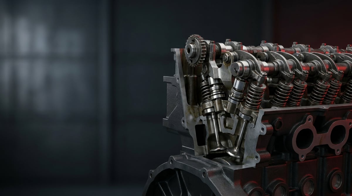
On heavy commercial vehicles, the cylinder head is where the engine breathes; the mechanism that measures, opens and closes that breath is the valve train. Out in the field, complaints like "the engine lost power," "it shakes at idle" or "compression dropped" often trace back to a worn valve, a seat that no longer seals, or a valve clearance that has drifted. When you consider that a tractor unit works well past 500,000 km with the engine constantly turning at high temperature and rpm, the valve train and adjustment shims are the quiet but decisive components of engine health. This guide explains, in field language, what the valve train does, how it fails, how it is diagnosed and replaced, and how to extend its service life.
What Is the Engine Valve Train (+ Adjustment Shim)? Function and Working Principle
The engine valve train is the mechanism that opens and closes the intake and exhaust ports in the cylinder head at the correct time, controlling the flow of air/fuel into the combustion chamber and the expulsion of burnt gases; it consists of the valves together with the springs, guides, seals, retainers and adjustment shims that support them.
The working principle is based on timing. The camshaft, driven from the crankshaft by a timing chain or gear set, rotates; the cam lobes push down on the valve stem — either directly or through a tappet/rocker arm — driving the valve off its seat and opening the port. Once the cam lobe passes, the valve spring returns the valve to its seat, closing the port tightly. The intake valve draws in fresh air, and the exhaust valve expels the burnt gas. Heavy commercial diesel engines typically have 4 valves per cylinder (2 intake + 2 exhaust); so a 6-cylinder engine runs with 24 valves.
In this system, valve clearance (valve lash) is a critical parameter. As the engine warms up, the metal expands; if no clearance is left, the hot valve does not close fully, gas leaks past the seat and the valve burns. If the clearance is excessive, you get ticking, delayed opening and power loss. This is exactly why adjustment shims (valve shims) are used to set that clearance precisely: these steel discs of varying thickness sit between the cam and the valve, adjusting the clearance to micron precision.
- Valve (intake/exhaust): Made of heat- and wear-resistant alloy; exhaust valves usually have a stellite-coated seating face.
- Valve spring: Holds the valve closed and prevents valve float at high rpm.
- Valve guide: Centres the valve stem and limits oil leakage and lateral sway.
- Valve seal (stem seal): Stops oil from leaking down the guide into the combustion chamber.
- Valve retainer and collets (keepers/locks): Lock the spring onto the stem.
- Adjustment shim / hydraulic lifter: Sets the valve clearance; by selecting a thickness in shim systems, automatically in hydraulic systems.
- Valve seat (insert): The sealing ring pressed into the cylinder head on which the valve sits.
Shim (Mechanical) and Hydraulic-Lifter Systems
Heavy commercial engines use two basic approaches to clearance management. In mechanical shim systems, the clearance is measured periodically and adjusted by hand by fitting an adjustment shim of the correct thickness; this is a durable structure that is reliable under heavy load and is preferred in many European-built heavy diesel engines. In hydraulic lifter (HLA) systems, the clearance is reset automatically by engine oil pressure; it requires no periodic adjustment but is sensitive to oil quality and pressure.
Difference Between Intake and Exhaust Valves
The intake valve is larger in diameter and runs relatively cooler; the exhaust valve, constantly exposed to hot burnt gas, is smaller, made of a more heat-resistant alloy and, in some engines, produced with a sodium-filled (heat-conducting) stem. For this reason, exhaust valves and seats typically wear faster and are the priority inspection point in diagnosis.
Since the whole valve train takes its motion from this shaft, wear on its lobes shows up directly in valve behaviour; see our guide on camshaft faults, diagnosis and replacement.
Vehicle / Engine Matching (general reference)
| Engine family (type/equivalent) | Typical application | Valves per cylinder | Clearance management |
|---|---|---|---|
| Mercedes OM457 / OM471 type | Actros, Travego, bus/tractor | 4 | Mechanical (shim/rocker adjusted) |
| MAN D20 / D26 type | TGA, TGX tractor | 4 | Mechanical adjustment |
| Volvo D13 type | FH, FM tractor | 4 | Mechanical adjustment |
| Scania DC13 type | R/S series tractor | 4 | Mechanical adjustment |
| DAF MX-13 type | XF tractor | 4 | Mechanical adjustment |
| Cummins ISX / ISL type | Heavy commercial, construction machinery | 4 | Mechanical / OHV rocker |
Failure Symptoms and Diagnosis
Valve train failures usually develop slowly and show themselves first as performance loss, then noise, and finally serious mechanical damage. The table below links the field complaint to the likely cause and the correct check method.
| Symptom | Likely Cause | Check / Verification |
|---|---|---|
| Metallic ticking when cold, easing as it warms up | Excessive valve clearance, worn shim/rocker | Clearance measurement with a feeler gauge; shim thickness check |
| Power loss, poor pull, struggling on hills | Burnt/unseated valve, compression leak | Cylinder compression test + leak-down test |
| Rough running at idle, vibration | Valve leakage in one cylinder | Per-cylinder compression; listening for air escape from the exhaust port |
| Bluish exhaust smoke, oil consumption | Hardened/torn valve stem seal, worn guide | Stem seal and guide clearance inspection; oil consumption monitoring |
| Irregular cranking, "banging" kickback | Spring breakage, valve sticking/binding | Visual inspection with cover off; spring free length / vertical measurement |
| Slow start, low vacuum, popping sound | Timing slip + valve seating fault | Timing mark alignment + compression comparison |
| Continuous hissing/blowing sound from the exhaust | Exhaust valve burn, seat erosion | Air escaping from the exhaust in the leak-down test; valve face inspection |
Compression and Leak-Down Test
These two tests are the backbone of valve diagnosis. The compression test gives each cylinder's pressure in bar; a large difference between cylinders points to the problem cylinder. The leak-down test lets you feed compressed air into the cylinder and listen for where it escapes: if the air comes from the intake manifold it is the intake valve, from the exhaust it is the exhaust valve, and from the crankcase/dipstick it is a ring/cylinder problem. This distinction pins the fault to the right place without removing the head.
Valve Clearance Measurement
In mechanical systems, the clearance is measured with a feeler gauge at the temperature specified by the engine manufacturer (usually a cold engine) and at the correct crank angle. If the measured value is out of tolerance, it is corrected by changing the shim. Before measuring, make sure the relevant valve is fully closed (cam heel up); a measurement taken in the wrong position throws off the entire adjustment.
Visual and Dimensional Inspection
Once the cover is removed, the valve face is checked for burning/erosion, the stem for scoring or discolouration (overheating), the spring for cracks or loss of tension, and the guide for ovality. The clearance between the valve stem and the guide is measured with a dial indicator; exceeding the tolerance means both oil leakage and a seating fault.
Further reading
For a plain-language technical overview of this subject, see the reference article on Wikipedia. Always confirm specific figures and procedures against the vehicle manufacturer service data.
Replacement / Installation Steps
- Preparation and timing mark: Bring cylinder 1 to top dead centre, note and photograph the timing/camshaft alignment marks.
- Upper assembly removal: Remove the air filter connections, injector/glow lines, valve cover and, if fitted, the upper intake manifold. Label the bolts.
- Camshaft/rocker shaft removal: Loosen the rocker or cam shaft bearings gradually, in the sequence specified by the manufacturer; release the spring preload evenly.
- Clearance/shim record: Before removal, write the existing shim thicknesses and measured clearances onto a cylinder-valve map; this becomes the starting reference for the new adjustment.
- Valve spring compression: Compress the spring with a proper valve spring compressor, carefully remove the collets (lock keepers); place the parts in separate trays by cylinder order.
- Valve and seal removal: Remove the valve from the combustion chamber side. Remove the stem seal; do not damage the guide mouth or the stem surface.
- Inspection and surface work: Check the valve seat and valve face; if necessary, have the valve seat cut/lapped at a competent workshop. Verify the new valve's seating contact with marker/dye.
- New part installation: Seat the new valve seal squarely onto the guide (use the fitting sleeve/cap), lubricate and insert the valve, fit the spring and retainer and seat the collets. Verify the collets are fully locked with a light tap.
- Cam/rocker assembly and torque: Tighten the cam shaft/rocker bearings gradually according to the manufacturer's torque and sequence values. Re-align the timing marks.
- Valve clearance adjustment: Measure each valve's clearance; where out of tolerance, select and fit an adjustment shim of the correct thickness and re-measure to confirm.
- Closing and test: Fit the valve cover with a new gasket and connect all lines. Start and warm the engine, check for leaks/noise; after a short road test, re-confirm the clearances.
Points to Watch (Common Mistakes)
- Disassembly without recording the timing marks: If the cam/timing alignment slips, valve-to-piston contact (engine damage) becomes a risk.
- Collets not fully seated: A half-locked collet flies off in operation; the valve drops into the combustion chamber and causes severe damage.
- Fitting the old valve mixed with a new one without lapping the seat: A new valve does not seat fully on an unprepared seat; the compression leak continues.
- Not following torque and sequence: If the cam shaft bearing is tightened unevenly, the shaft binds/bends and the valve timing is disrupted.
- Dirty assembly: If swarf or gasket residue gets into the combustion chamber, the valve face is scored at first start.
- Not verifying diameter/stem length on an equivalent part: The wrong dimension causes the valve not to close and leads to engine damage.
Technical Values and Check Points
The values below are typical/general reference ranges for heavy commercial diesel engines. The exact value varies by engine; the OE service manual always takes precedence.
| Parameter | Typical reference range | Note |
|---|---|---|
| Intake valve clearance (cold) | ~0.20 – 0.40 mm | Engine-specific; the manual takes precedence |
| Exhaust valve clearance (cold) | ~0.40 – 0.60 mm | Exhaust is generally larger |
| Cylinder compression (healthy) | ~24 – 32 bar (≈350–465 psi) | Difference between cylinders should not exceed 10% |
| Leak-down acceptance limit | Below 15–20% is ideal | Above this, suspect valve/ring |
| Valve operating temperature (exhaust) | ~300 – 700 °C locally | Surface temperature, varies with load |
| Stem–guide clearance | ~0.03 – 0.08 mm | Exceeding it means oil leak/seating fault |
| Adjustment shim thickness step | ~0.05 mm increments | The shim series is engine-specific |
The torque of the fasteners is at least as important as the clearance. The torque values below are a general guiding reference; refer to the manual for the actual value.
| Fastener | Typical torque range | Method |
|---|---|---|
| Valve cover bolt | ~15 – 30 Nm | Sequential, gradual |
| Rocker/cam bearing bolt | ~40 – 90 Nm (+ angle possible) | Per manufacturer sequence |
| Adjustment lock nut (rocker type) | ~25 – 45 Nm | Lock without disturbing the adjustment |
- Record the compression values for each cylinder in writing; trend tracking is more valuable than a one-time measurement.
- Look for burning/erosion on the valve face, discolouration on the stem (excess heat) and cracks in the spring.
- Verify the new valve's seating contact with a dye/marker test as an uninterrupted 360° ring.
- Mark the shim numbers and positions on a map; they become a reference at the next service.
Maintenance and Service Life
With correct maintenance, the valve train can run for the life of the engine without a major overhaul; when neglected, it leads to costs that can extend all the way to a complete cylinder head rebuild. In heavy commercial use, the main factors that determine service life are oil quality, timely clearance maintenance and protecting the engine from overheating.
- Periodic clearance check: In mechanical systems, measure the valve clearances at the interval specified by the manufacturer (typically a certain km/operating hours) and correct with a shim if necessary.
- Correct oil and filter: Especially in hydraulic lifter systems, oil pressure and cleanliness directly affect valve operation; use oil of the approved viscosity.
- Heat management: Keep the cooling system and thermostat maintained; chronic overheating rapidly burns the exhaust valves.
- Quality fuel and correct injection: Poor combustion and late injection cause deposits and local heating on the valve face.
- Stem seal and guide monitoring: If oil consumption is rising, early intervention is cheaper than a complete cylinder head rebuild.
- Kit replacement at overhaul: When the head is opened, renewing the valve seals, worn springs and shims as a group rather than one by one is safer in the long run.
In short, valve train maintenance, when done "on schedule rather than when a fault appears," both protects fuel economy and prevents unexpected roadside breakdowns and expensive engine damage. A small clearance adjustment is usually far cheaper than a burnt exhaust valve.
The VADEN ORIGINAL Engine Valve product family covers the valve adjusting shims and the valve cover group: the adjusting shims are offered across the 2.00-3.95 mm thickness series in 0.05 mm steps, plus a complete shim set, together with the valve cover, its cover gasket and cover bolt, produced with OE-type/equivalent dimensions and heat resistance for heavy commercial diesel engines. This lets you set the valve clearance to the specified value and close the cover leak-free while carrying out the diagnosis, replacement and maintenance processes described above. Use the VADEN catalogue and cross-reference list to select the correct reference by your vehicle's engine number.
Related categories: Valve · Adjusting Shim · Cover Gasket · Cover
Related technical guides: Exhaust Manifold: Cracks, Leaks, Replacement & Torque Guide · Engine Cylinder Head Group: Faults, Replacement & Maintenance · Exhaust / Engine Brake: Faults, Replacement & Maintenance Guide · Oil Cooler: Failure Symptoms, Replacement & Maintenance Guide · Truck Oil Pan Group: Faults, Replacement & Maintenance Guide
Application and compatibility: Vehicle compatibility catalogue · Engine compatibility catalogue
Vehicles and engines mentioned in this guide: Volvo D13 · DAF MX-13 · Mercedes-Benz OM457 · Volvo FM · Volvo FH · MAN TGA · MAN D2676 · MAN D2066
Main guide: What Is a Crankshaft? Function, Failure Symptoms and Maintenance
Tags
Frequently Asked Questions
- How often should valve clearance be adjusted?
- This depends on the engine type. In mechanical shim/rocker systems, it should be checked at the maintenance interval set by the manufacturer (a certain km or operating hours). In hydraulic lifter systems, routine adjustment is not required; however, if there is ticking or power loss, it should still be checked. For the exact interval, the vehicle's service manual takes precedence.
- What are the symptoms of a burnt valve?
- The most typical symptoms are noticeable power loss in the relevant cylinder, vibration/rough running at idle, a continuous hissing sound from the exhaust, and a low value in that cylinder in the compression test. In the leak-down test, air coming from the exhaust side confirms an exhaust valve burn.
- Should just one valve be replaced, or the whole set?
- If a single valve is damaged, technically only that one can be replaced; however, if the cylinder head is already open, renewing the other valves, seals and fatigued springs of the same age and mileage usually makes more sense in terms of labour and the cost of a second disassembly. Exhaust valves in particular are assessed as a group.
- What does a valve adjustment shim do, and can any thickness be fitted?
- The adjustment shim is a steel disc that precisely sets the clearance between the cam and the valve. The thickness is not chosen at random; the correct shim thickness is selected by calculating the difference between the measured existing clearance and the target clearance. The wrong shim causes the valve to burn or to tick.
- Does the engine need to be dismantled to change the valve seal?
- The stem seals can be replaced without completely removing the cylinder head, by holding the cylinder with compressed air with the piston at top dead centre; this is a common method. However, if there is also guide wear or the valve faces are damaged, the head must be removed and machined in a workshop.
- How much difference is normal in a compression test?
- In a healthy engine, the compression difference between cylinders is generally accepted to be no more than 10%. Larger differences point to a valve seating problem, a burnt valve or a ring leak in the low-value cylinder, and should be distinguished with a leak-down test.
- Does fitting an equivalent valve train harm the engine?
- An equivalent (OE-type/equivalent) valve train produced to the correct dimensions and quality can be used safely. What matters is that the valve diameter, stem length, guide dimension and material strength conform to the OE values. The wrong dimension or a part with low heat resistance is the real risk; that is why the part number and cross-reference must always be verified.
- When I hear valve ticking, should I stop immediately?
- A light tick that eases as the engine warms up usually points to the clearance adjustment and requires adjustment at the first opportunity. But if it comes with a hard, irregular metallic knock, power loss or kickback, there is a risk of valve/spring breakage; in that case, stopping the engine without straining it and having it checked is the cheapest way to save the engine.
- In a leak-down test, what does the point where the air escapes tell you?
- The escape point identifies the faulty component directly. Air heard at the intake manifold means the intake valve is not seating, air at the exhaust means the exhaust valve is leaking, and air from the crankcase or dipstick points to the rings or cylinder. The compression test shows which cylinder is weak; the leak-down test shows why, without removing the cylinder head.
- Does the seat have to be lapped before a new valve is fitted?
- Yes. A new valve will not seat fully on an unprepared seat and the compression leak continues, so where needed the seat is cut or lapped at a competent workshop. After assembly, confirm the seating contact with a dye or marker test: the mark must form an uninterrupted 360 degree ring. A broken ring means the valve still leaks and will eventually burn.
Related Articles

Oil Filter Cap and Housing: Leaks, Cracks and Seal Replacement
Truck engine oil filter cap and housing: why plastic caps crack, O-ring leak causes, bypass valve faults, and correct torque and seal replacement steps.
Piston Rings: Oil Consumption, Compression Loss and Replacement
Ring-related oil consumption and compression loss in truck diesel engines: how rings seal, blow-by and leak-down tests, ring gap and replacement.
Intake Manifold and Intake Pipe: Faults, Diagnosis, Repair
How the intake manifold and charge air pipe work on truck diesel engines, how to spot boost leaks, run a pressure test and fit them leak free.


