Transmission Shift Cylinders: Failure, Replacement & Care
On a truck gearbox, gears that grind, refuse to engage or jump out often trace to a leaking pneumatic shift cylinder, not the transmission: diagnosis and repair.
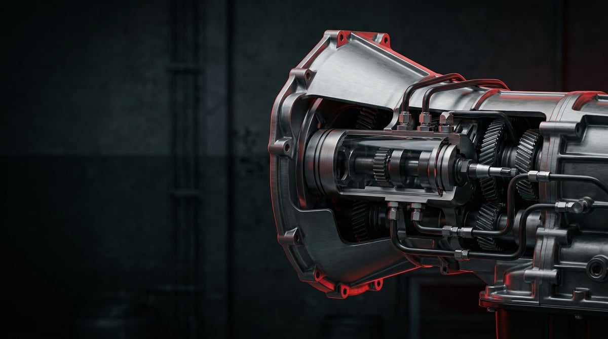
On heavy commercial vehicles, gears that grind, refuse to engage or jump out on their own usually point to a single place: the gear shift control cylinders (Schaltzylinder) on the transmission. The driver pulls the lever but the truck simply "won't go in"; pull over, open the cab and up top you find a hissing air leak, an oil-weeping cylinder or a loosened air line. This guide covers the subject end to end — from failure symptoms to replacement steps, from technical figures to service life — the way a technician wrestling with these cylinders in the field, a fleet maintainer or a spare-parts specialist actually needs it.
What Are Transmission Gear Shift / Shifting Cylinders? Function and Working Principle
A transmission gear shift control cylinder (Schaltzylinder) is a pneumatic actuator that carries out gear changes in a heavy commercial vehicle transmission with the help of compressed air, converting the command from the driver or the gear control unit into mechanical movement of the shift fork inside the transmission.
The working principle is essentially simple: compressed air, directed through the solenoid valves (gear control valve block), enters the chamber on one side of the cylinder and pushes the piston. The push rod attached to the piston is connected to the shift rail/fork inside the transmission; that fork in turn moves the relevant synchronizer sleeve to engage the gear. When air is applied to the opposite chamber, the piston travels the other way and the gear is either put into neutral or shifted to the next step. On automated and semi-automated transmissions (AMT), these commands come from the TCU, whereas on mechanical/pneumatically assisted transmissions they come directly from the driver's lever.
On heavy commercial vehicles these cylinders may be single-acting (spring return) or double-acting; some systems use separate cylinders for split (high/low group) and range changes. Range-change and splitter cylinders belong to the same family.
- Cylinder body: Usually cast aluminium; houses the air chambers and the piston bore.
- Piston and push rod: The element driven by the air; connected to the shift fork directly or through a linkage.
- Sealing elements: Piston seal/O-ring, rod wiper and body gaskets — the most critical wear parts of the system.
- Spring (on single-acting types): The return spring that brings the piston back when air is cut off.
- Air connection ports: The fittings/hose connections running to the valve block.
- Position sensor (on some AMTs): The feedback sensor that reports gear position to the TCU.
The Difference Between Pneumatic Control and the Manual Lever
In a classic manual transmission the driver engages the gear directly with lever force. In pneumatically controlled systems the driver only issues the command; the actual engagement force is generated by compressed air. On heavy transmissions (16+ gears) this reduces driver fatigue, but it makes the system sensitive to air leaks and cylinder failures.
Single-Acting and Double-Acting Cylinders
In a single-acting cylinder the air pushes in one direction and a spring provides the return; it is simpler but prone to spring fatigue. In a double-acting cylinder the air controls both directions; it delivers a more precise and faster shift and is preferred for critical functions such as split/range.
Its Place in the System: The Valve Block, Cylinder and Fork Chain
The cylinder does not work on its own; the air preparation unit (dryer, pressure), the gear control valve block, the cylinder and the mechanical fork–synchronizer chain all work together. In diagnosis you must consider this entire chain — because the source of a "gear won't engage" symptom may be the cylinder, but it may just as easily be a valve, an air leak or mechanical wear.
| Application / System | Typical Cylinder Type | Example Use |
|---|---|---|
| Range (high/low group) change | Double-acting, with position sensor | 16-speed heavy tractor transmissions |
| Splitter (intermediate step) control | Single/double-acting, short stroke | In split gear groups |
| Gear select/shift | Double-acting actuator | AMT automated transmissions |
| Assisted engagement (servo shift) | Single-acting, spring return | Pneumatically assisted manual transmissions |
Failure Symptoms and Diagnosis
Gear shift control cylinder failures mostly develop gradually: first shifts that resist, then gears that do not fully engage, and finally the vehicle can be left immobile. Reading the symptom correctly prevents unnecessary parts replacement.
| Symptom | Possible Cause | Check / Verification |
|---|---|---|
| Gear won't engage / stays in neutral | Punctured piston seal, internal air leak; insufficient air pressure | Measure system pressure with a gauge; run a leak test (soapy water) at the cylinder ports |
| Gear engages very stiffly | Fouling/corrosion inside the cylinder, piston seizing; low pressure | Check the air preparation pressure; observe cylinder stroke manually in neutral |
| Gear jumps out on its own | Weak return spring, worn rod guide, fork clearance | Check the piston return force; measure the mechanical fork clearance |
| Constant air leak / compressor always cutting in | Body gasket or rod wiper seal torn; port fitting loose | Pressure-drop test with engine stopped; soap-bubble check at every port |
| Shift delay / slow response | Partially blocked air line, valve block fault, seal swelling | Measure the valve outlet pressure; check the hose inner cross-section and the filter |
| AMT fault code (gear position/actuator) | Position sensor, cylinder stroke problem, wiring | Read the fault code with a diagnostic tool; monitor the sensor signal in live data |
| Oil/moisture-laden air venting | Saturated dryer, moisture in the system, internal corrosion | Check the air dryer cartridge and the tank drain |
Air First, Then the Cylinder
The golden rule in diagnosis: before blaming the cylinder, verify the air supply. Insufficient system pressure, a saturated dryer or a blocked line will make a sound cylinder look "faulty". Do not remove the cylinder until you have seen the system pressure at its working value.
Internal Leak or External Leak?
An external leak (air escaping around the body/rod to the outside) is easily found with soapy water. An internal leak (crossover between chambers through the piston seal) is more insidious: the cylinder looks sound from the outside but cannot hold pressure. When an internal leak is suspected, pressurize the cylinder from its port and listen for a leak at the opposite port.
Mechanical or Pneumatic?
Sometimes the problem is not in the cylinder but in the wear of the fork/synchronizer. If the cylinder pushes soundly and the rod completes its full stroke yet the gear still does not engage, the fault is inside the transmission. Replacing the cylinder without making this distinction is a waste of time and parts.
Further reading
For a plain-language technical overview of this subject, see the reference article on Wikipedia. Always confirm specific figures and procedures against the vehicle manufacturer service data.
Replacement / Installation Steps
- Release the pressure: Drain the air tanks to zero out the system pressure; make sure you see 0 bar on the gauge.
- Prepare the vehicle: Switch off the ignition, disconnect the battery terminal (especially on AMTs), and clean the work area and the top of the transmission.
- Mark the connections: Photograph and label the air hoses running to the cylinder and the sensor socket if present; do not mix up the port orientations.
- Disconnect the air hoses: Loosen the fittings with the correct wrench; cap the hose ends so no dust/dirt gets in.
- Disconnect the sensor/socket: If there is a position sensor, release its lock and carefully unplug the socket; do not force the clips.
- Remove the cylinder: Loosen the fixing bolts in a crosswise sequence; take the cylinder off without straining the rod connection.
- Check the fork and seat: Once the cylinder is out, inspect the shift fork, the rod seat and the mating surface for wear/cracks.
- Clean the mating surface: Remove old gasket residue and dirt; smooth the surface without scratching it.
- Prepare the new cylinder: Verify that the stroke, port orientation and rod connection of the new/equivalent cylinder are identical to the one removed; use new gaskets/O-rings.
- Fit and torque: Seat the cylinder; tighten the bolts to the OE value in a crosswise sequence, in stages (see the table below).
- Connect and test: Connect the air hoses and sensor to the correct ports, pressurize the system, run a leak test, and with the engine running try all gear steps.
Points to Watch (Common Mistakes)
- Fitting a cylinder with the wrong stroke/type — cylinders that look alike may belong to a different function.
- Tightening the bolts in one pass and in a straight sequence — this distorts the body and causes leaks; torque crosswise and in stages.
- Letting dirt/moisture into the air line — do not leave the ports open during assembly.
- Neglecting the dryer and air preparation unit — moist air will soon corrode even a new cylinder from the inside.
- Skipping the calibration/learning procedure after replacement on an AMT — the TCU needs to relearn the cylinder position.
- Forcing the rod connection with a hammer — the fork and rod bend and shifts deteriorate.
Technical Figures and Check Points
The figures below are typical/general reference ranges for heavy commercial vehicle pneumatic transmission systems. They vary by transmission make and model; for exact values the OE service manual prevails.
| Parameter | Typical / General Reference Range | Note |
|---|---|---|
| System working pressure | ~8–12.5 bar (≈116–181 psi) | Air preparation unit outlet; cut-off pressure depends on the model |
| Gear control min. working pressure | ~6.5–8 bar (≈94–116 psi) | Below this, shifts become harder/delayed |
| Cylinder operating temperature | ≈ −40 °C to +100 °C | The seal material is chosen for this range |
| Piston stroke tolerance | ±0.5–1 mm of the OE value | Excessive deviation means incomplete engagement |
| Acceptable static leak | In practice "zero" is targeted | No perceptible drop should occur in the pressure-drop test |
Typical torque ranges for fixing and connection elements (general reference; the OE value prevails):
| Connection Point | Typical Torque Range | Description |
|---|---|---|
| Cylinder fixing bolts (M8) | ~20–30 Nm | Crosswise and staged tightening |
| Cylinder fixing bolts (M10) | ~40–55 Nm | Staged to prevent body distortion |
| Air port fitting | ~12–20 Nm | Over-tightening damages the thread/fitting |
| Rod / fork connection nut | Per the OE value | If there is a safety pin/lock, it must be fitted |
- Always verify the system pressure at its working value; a cylinder is not to be blamed under low pressure.
- Visually check that the cylinder rod completes its full stroke and turns freely.
- Run a leak scan with soap bubbles at all air ports and around the rod.
- On an AMT, run the gear learning/calibration procedure after replacement.
- Keep moisture out of the system by checking the air dryer and the tank drain.
Maintenance and Service Life
Gear shift control cylinders are long-lived when run on a clean, dry air supply; the bulk of early failures stem from systemic causes (moisture, dirty air, low pressure). The focus of maintenance is therefore not the cylinder alone but the whole air chain.
- Replace the air dryer cartridge according to the manufacturer's interval; moisture is the number-one enemy of the seal and the body.
- Drain the air tanks regularly (by hand if there is no automatic drain).
- At periodic service, check for leaks at the cylinder ports and around the rod.
- If stiffness/delay in shifting starts, address the fault before it grows.
- Inspect the connection hoses for cracks, chafing and looseness.
- On AMT systems, read the fault codes periodically to catch early warnings.
A gear shift control cylinder that is correctly fitted, has quality seals and is fed with dry air will serve trouble-free through a long maintenance interval on the vehicle. Most premature replacements arise not from the cylinder itself but from neglected air preparation maintenance; so the most economical approach when replacing a cylinder is to overhaul the rest of the system as well.
VADEN ORIGINAL offers a broad family of Transmission Gear Shift / Shifting Cylinders (Schaltzylinder) for heavy commercial vehicles; produced in OE-equivalent stroke and port configurations suited to range, splitter and select/shift applications, these cylinders deliver reliable gear engagement and long service life in your fleet vehicles with correct part matching and quality sealing elements. When choosing the right cylinder for your vehicle, do not forget to verify the transmission type and the OE number.
Related categories: Split Cylinder · Split Cylinder · Gear Lever Cable · Gear Control Cable · Housing · Pipe
Related technical guides: Truck Retarder: Faults, Replacement & Maintenance Guide · Heavy-Duty Truck Gearbox: Faults, Replacement & Maintenance · Transmission Shift Tower: Faults, Replacement & Maintenance · Transmission Control Unit (TCU): Faults, Replacement, Care
Application and compatibility: Vehicle compatibility catalogue · Engine compatibility catalogue
Tags
Frequently Asked Questions
- How do I tell that a gear shift control cylinder has failed?
- The most typical signs are a gear that engages late or not at all, jumps out on its own, and a constant air leak around the cylinder. If you see these, check the system pressure first and then the cylinder.
- The gear won't engage — is the cylinder definitely the problem?
- No. A "gear won't engage" symptom can also stem from low air pressure, a blocked line, a valve block fault or mechanical fork/synchronizer wear. Before removing the cylinder it is essential to verify the air supply.
- Should I have the cylinder repaired or replaced outright?
- If a seal/O-ring kit is available and the body and rod are sound, repair is possible; but if there is body corrosion, rod wear or a recurring fault, complete replacement is safer and longer-lasting.
- Does an aftermarket cylinder last as long as OE?
- An OE-equivalent will give a life close to OE if it is made with the right stroke/port/type and quality seal material. What is critical is correct part number matching and a dry air supply.
- How do I find out whether an air leak is coming from the cylinder?
- Pressurize the system and apply soapy water to the cylinder ports and around the rod; bubbling reveals the leak point. For an internal leak, pressurize the cylinder from one port and listen for air coming out of the opposite port.
- Is calibration needed after replacement?
- On automated/semi-automated (AMT) transmissions, yes; a calibration/learning procedure must be run with a diagnostic tool so the TCU relearns the cylinder position. On classic pneumatically assisted systems it is generally not required.
- What shortens cylinder life the most?
- Moisture and dirty air entering the system. A saturated air dryer, tanks that are not drained and low pressure wear out the seals and the body quickly. That is why the heart of maintenance is the air preparation unit.
- How do I tell that I fitted the wrong cylinder?
- The gear does not engage fully, the stroke stays short/long, shifts resist, or the AMT throws a fault code. In that case, re-compare the OE number, stroke and port orientation of the removed and the fitted cylinder.
- What is the difference between a single-acting and a double-acting cylinder?
- In a single-acting cylinder the air pushes in one direction only and a return spring brings the piston back; it is simpler but prone to spring fatigue. In a double-acting cylinder the air is controlled in both directions, which gives a faster and more precise shift. That is why double-acting types are preferred for critical functions such as split and range.
- What happens if I connect the air hoses to the wrong ports?
- The gear moves in the wrong direction or does not engage at all; on an AMT this can cause a calibration error and even lock up the transmission. Photograph and label the hoses and the sensor socket before removal, and mark the port orientations. After fitting, pressurize the system and try every gear step so the mistake shows up immediately.
Related Articles
Transmission PTO: Faults, Replacement and Maintenance Guide
A workshop guide to truck transmission PTO units: how they work, why they fail to engage, correct backlash setting on fitting and habits that extend life.
Transmission Housing Repair Kit & Valve: Faults & Replacement
Understand how the pneumatic shift valve and its seal kit work, spot air leaks early, replace the parts correctly and extend service life on trucks.
Transmission Shift Tower: Faults, Replacement & Maintenance
Transmission shift tower faults, diagnosis, replacement steps, torque and pressure values, maintenance and FAQ for heavy commercial vehicles — VADEN guide.


