Disc Brakes vs. Drum Brakes: A Heavy-Duty Vehicle Comparison
Drum brake vs disc brake in heavy trucks: how each works, heat and fade behaviour, pad and shoe wear, slack adjuster checks, and drum machining limits.
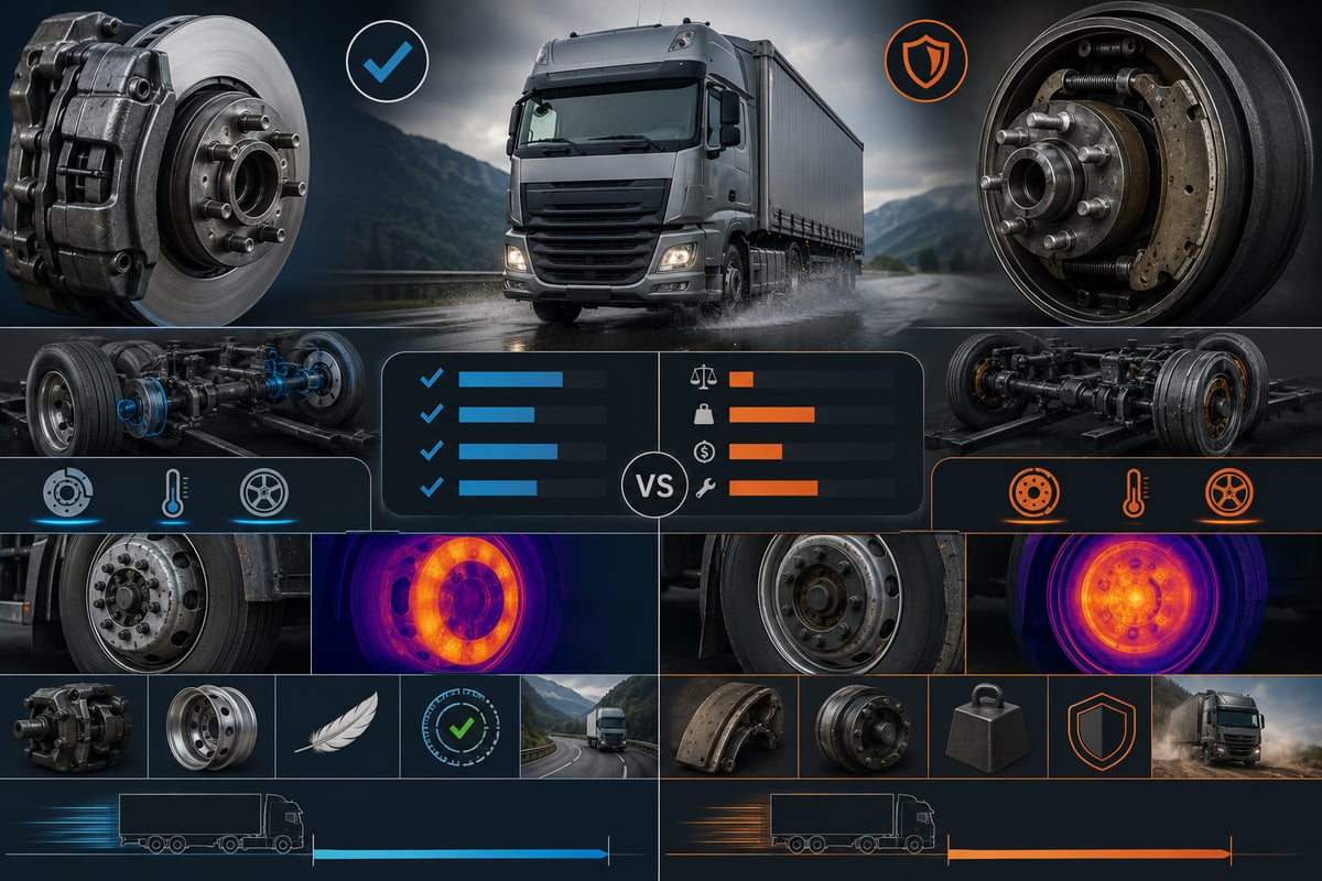
Two tractor units sit side by side in the same yard: one carries air disc brakes on the front axle and drum brakes on the rear, the other is disc all round. Both pull the same load down the same grade. Yet on one, a pad change is done inside an hour; on the other, a shoe change stretches into half a day. The driver of one mentions the pedal sinking lower after a long descent; the driver of the other feels nothing change on the same hill. In heavy commercial vehicles, disc and drum brakes are not an old and a new version of the same idea — they are two separate architectures doing the same job with different physics. This guide sets them side by side: how each works, how each carries heat away, what wear looks like on each, why one is chosen over the other on a given vehicle, and how the two are balanced when they end up on the same combination.
Why do two brake architectures still coexist on heavy vehicles?
In passenger cars the debate is settled: disc brakes are fitted almost everywhere. In heavy commercial vehicles it is not. A truck's brake system is not tasked only with stopping the vehicle; it has to hold a load of tens of tonnes under control for kilometres on a long descent, lock the vehicle mechanically at a standstill, manage the trailer's own brakes, and do all of this in mud, salt and dust for hundreds of thousands of kilometres a year.
This job description carries conflicting demands. You want to shed heat quickly, but you also want to keep the friction surface protected from dirt. You want to cut service time, but you also want to keep the initial purchase cost down. The drum brake represents the enclosed, protected and inexpensive answer; the air disc brake represents the open, cool-running and fast-to-service one. No single vehicle type ranks all of these demands the same way, which is why both have stayed in the market.
The result is today's fleet mix: most new-generation long-haul tractors run disc brakes on all four wheel ends, a large share of construction-site vehicles stay on drums, and trailers are split roughly down the middle. The right question is not "which one is better", but which one is right for this job, and how to get the best performance out of whichever system is already fitted.
How does a drum brake work? The shoe, S-cam and slack adjuster chain
In a drum brake, the friction surface is the inner face of a hollow cylinder that rotates with the wheel; this cylinder is called the drum. Inside it, two shoes sit on a backing plate fixed to the axle; the friction material riveted or bonded to the outer face of each shoe is called the lining. When the brake is applied, the shoes are pushed outward, the linings press against the inner face of the drum, and the resulting friction torque slows the wheel.
In heavy vehicles, the mechanism that spreads the shoes is almost universally the S-cam arrangement. The chain works like this: pressing the pedal sends air to the brake chamber; the chamber's pushrod applies force to the slack adjuster; the slack adjuster rotates the shaft of the S-shaped cam; the lobes of the cam press against rollers on the shoes and force them apart. When the pedal is released, return springs pull the shoes back in.
This chain has two consequences. The force travels through a series of mechanical links, so the play in every joint, the fatigue of every spring and the stiffness of every shaft bearing all show up in the result. Second, as the lining wears, the shoes have farther to travel; if this clearance is not taken up regularly, the chamber's stroke grows and the brake weakens over time. That is the defining trait of a drum brake: it is a system that needs adjustment.
Leading and trailing shoe: why does one wear faster?
In an S-cam layout, the two shoes do not do the same amount of work. Depending on the direction of rotation, one shoe sits in a position where the friction force presses it further into the drum; this is the leading shoe, and it generates more torque through this self-energising effect. The other is the trailing shoe. The result shows up on the bench: of two shoes pulled from the same drum, one is noticeably thinner than the other. This is a normal outcome of the design; but if the difference is extreme, the cam shaft, the rollers or the anchor pin should be checked for binding.
Self-energising also gives the drum an advantage: for the same chamber force it can generate a higher brake torque than a disc arrangement. But the torque produced is multiplied by the friction coefficient; once the lining heats up and that coefficient drops, the resulting loss is larger than the drop in the coefficient itself. This is the mathematical reason a drum brake fades more sharply once it gets hot.
How does an air disc brake work? The caliper, disc and pad chain
In an air disc brake, the friction surface is both faces of a flat ring that rotates with the wheel; this ring is called the disc. The horseshoe-shaped body that straddles the disc is the caliper, and it houses two pads. When the brake is applied, the force the chamber generates from air pressure is multiplied by a lever-and-tappet mechanism inside the caliper; the thrust pistons press the inner pad against the disc, and the caliper slides on its own guide pins to pull the outer pad against the disc's other face.
This chain is far shorter than the drum's. There is no S-cam, no roller, and no externally visible slack adjuster; the clearance created by pad wear is taken up automatically inside the caliper, in small steps, at every brake application. In exchange, the caliper itself is more delicate: the guide pins and their boots, the gearing of the adjuster mechanism, and the piston seals determine how long the system lasts. Caliper fault symptoms, guide-pin maintenance and service procedure are covered in the air disc brake caliper guide.
The disc system's second defining trait is the absence of self-energising. The pad is pressed square onto the disc; the friction force does not drive the pad further into it. This means a larger input force is needed for the same braking effect, but in return the torque produced varies almost linearly with input pressure. This is why electronic brake systems work more comfortably with disc arrangements: torque is easy to predict, so ABS and EBS interventions can be tuned more finely.
Component by component: mapping the drum and disc arrangements
The most common mistake when comparing the two systems is trying to match parts by name. The correspondence is not one to one: a job that three separate parts do on the drum side can be handled by a single body on the disc side. The table below gives the functional matching that actually matters for service work.
| Function | Drum brake equivalent | Air disc brake equivalent | Service-relevant difference |
|---|---|---|---|
| Rotating friction surface | Inner face of the drum | Both outer faces of the disc | On a drum wear increases the diameter; on a disc it reduces thickness |
| Stationary friction element | Two shoes and their linings | A pair of pads | Linings are riveted, pads are bonded to a steel backplate |
| Force multiplication and application | Slack adjuster, S-cam and rollers spread the shoes | Lever, tappet and thrust pistons inside the caliper | Visible from outside on a drum, enclosed in the caliper on a disc |
| Taking up wear clearance | Automatic slack adjuster | Automatic adjuster mechanism inside the caliper | Verified from outside on a drum; works sealed on a disc |
| Self-energising effect | Clearly present on the leading shoe | Absent; force is transmitted linearly | The disc arrangement suits electronic control better |
| Wear monitoring | Lining thickness measured through an inspection hole | Pad wear sensor plus visual check | On a disc the warning reaches the driver; on a drum it is left to the technician |
| Resurfacing the friction face | A drum can be machined, up to a maximum diameter | A disc is not machined in most applications; it is replaced | Drums have an intermediate repair step that discs do not |
In this table, "the equivalent function" should not be confused with "the same part". Both systems use a service brake chamber and a spring parking chamber, but the stroke behaviour expected on a disc axle cannot be read the same way as on a drum axle.
Heat, fade, water and mud: where the difference actually comes from
Every practical difference between the two systems traces back to two simple facts: the direction in which a heated body expands, and whether the friction surface is open to the outside world.
Direction of expansion and fade behaviour
When a drum heats up, it expands outward — the friction surface moves away from the shoes. To keep up with the growing diameter, the shoes have to spread further, which means a longer chamber stroke and a pedal that sinks lower. This is why a driver who keeps braking through a long descent complains that the pedal is gradually reaching the floor. A disc, by contrast, expands by getting thicker toward the pads as it heats up; this works to shorten the stroke rather than lengthen it, so pedal feel is far less affected by heat.
The second factor is the friction material itself. When a lining or pad overheats, gas and resin break down at its surface and the friction coefficient temporarily drops; this is fade. Fade occurs in both systems, but on a drum three effects stack on top of each other: heat is shed slowly, the drum's own expansion lengthens the stroke, and the self-energising effect makes torque fall out of proportion once the coefficient drops. That is why the difference between the two systems is not felt on flat roads but becomes obvious on a mountain descent.
Water, mud, salt and stone chips
The drum's enclosed body shields the friction surface from mud, dust and stone chips; this is the most concrete reason drums are still chosen for construction-site and quarry vehicles. But the protection cuts both ways: water and mud that do get in do not leave easily either. After fording deep water, water trapped inside a drum lowers the friction coefficient; the brake stays weak for several applications, then grabs suddenly and hard once it dries out.
On a disc arrangement, water is wiped off by the pads and flung away within a few brake applications, so the loss of wet performance is much shorter-lived. On the other hand, the disc face itself is exposed to road salt in winter and to moisture while parked. The real weak point of a disc arrangement in winter is the caliper's guide pins: once salt and moisture work past a torn boot, a pin seizes, the caliper can no longer slide freely, and the two pads start wearing at very different rates.
Criterion by criterion: which one leads where?
The table below compares the two systems on the criteria a fleet operator actually weighs when deciding. No single row is decisive on its own; the weighting shifts with vehicle type.
| Criterion | Drum brake | Air disc brake | Result in the field |
|---|---|---|---|
| Heat rejection | Mass absorbs heat, sheds it slowly | Open, ventilated surface sheds heat fast | Disc has the edge under repeated, extended braking |
| Fade behaviour | Stroke lengthens with heat, torque drops sharply | Pedal feel and torque stay stable | Difference becomes obvious on mountain descents |
| Mud, dust and stone chips | Enclosed body protects the friction surface | Surface is exposed, wears fast in abrasive conditions | Drum has the edge on site and off-road work |
| Adjustment need | Slack adjuster and stroke need regular checking | Adjustment works sealed inside the caliper | Periodic checks cannot be skipped on a drum |
| Service time | Pulling the drum means spring and pin work | Pad change is done by opening the caliper | Labour time per wheel end is shorter on a disc |
| Parts cost | Drum and shoe kit is generally economical | Disc, pads and caliper cost more | Drum wins on upfront cost, disc on total ownership |
| Weight | Large-diameter drum and hub assembly is heavy | Similar or somewhat lighter depending on design | Difference varies by axle; not a general rule |
The one-sentence summary is this: the air disc brake leads on performance and service ease, the drum brake leads on cost and resilience in harsh conditions. But that summary is only useful when buying a new vehicle. If you already own the vehicle, the right question is "how do I close the weak point of the system I have" — on a drum vehicle the answer is stroke discipline, on a disc vehicle it is caliper guide-pin maintenance.
How can disc brake pad wear be read?
The biggest advantage of a disc arrangement is that wear is visible. On most vehicles, remaining pad thickness can be assessed through the caliper's inspection opening; on many applications a wear sensor embedded in the pad triggers a dashboard warning once thickness drops to a set point. Even so, the sensor should never be treated as the only indicator — a sensor with a broken wire will never raise a warning.
The real information is not in the thickness but in the wear pattern; the pattern usually tells a story about the caliper or the disc rather than the pad itself.
- Inner pad noticeably thinner than the outer pad: At least one caliper guide pin has seized, and the caliper can no longer slide freely.
- One end of the pad thinner than the other: The caliper is not sitting square on the disc; check guide clearance, caliper carrier and mounting torque.
- Very different wear between the two wheels of the same axle: One side is not releasing or the other is not getting enough pressure; check the chamber, the air line and the caliper together.
- Shiny, glazed appearance on the pad face: Overheating or light continuous contact; the friction coefficient has dropped.
- Friction material separating from the steel backplate: Excessive heat or a material defect; replace the part immediately.
- Steering wheel vibration under braking: Usually not the pad, but disc thickness variation or run-out.
The only correct answer to "at what thickness should the pad be changed" is the minimum remaining thickness given by the axle manufacturer; the practical rule in the field is not to wait, because wear accelerates in the last few millimetres, and backplate-to-disc contact can scrap both the disc and the caliper in a single event.
What determines the service life of a disc brake pad?
The mileage figures quoted for pad life can differ by several multiples even between vehicles of the same make and model. The cause is not the pad itself but the difference in the work it is asked to do. A pad is a consumable, and what it consumes is not distance but kinetic energy converted into heat. Of two vehicles covering the same distance, the one running a hilly route burns through several times more energy than the one running on flat ground.
In roughly descending order of importance, life is determined by: route profile and how much descent it involves, load condition, driving style, the proportion of urban stop-and-go, whether the retarder and exhaust brake are actually used, how freely the caliper guides slide, the condition of the disc surface, the friction material grade, and the brake balance between tractor and trailer. The first five sit with operations; the remaining four sit with maintenance.
The most commonly overlooked factor is bedding-in. A new pad and disc have not yet developed full contact across their surfaces; in the first kilometres the actual contact area is very small. If a hard stop from high speed is made before bedding-in is complete, this small area overheats, the surface glazes, and the part loses part of its performance from day one. Signs that a pad needs changing, and realistic life expectations, are covered in detail in the guide on when to replace brake pads.
Standards and further reading
This subject is governed by the equipment rules for air-braked commercial vehicles. In the United States the federal air brake standard, FMVSS 121 (49 CFR 571.121) defines the reservoirs, protection and timing a compliant system must provide, and Europe applies the equivalent limits of UNECE Regulation No. 13. For further detail, see the illustrated reference guide at airbrakecompressor.com. Always confirm specific figures against the current regulation and the vehicle manufacturer service data.
Outside the United States the equivalent duties sit in national law. In the United Kingdom, regulation 18 of the Road Vehicles (Construction and Use) Regulations 1986 requires every part of the braking system to be maintained in good working order. In Canada, air brake systems fall under the Motor Vehicle Safety Regulations, which contain CMVSS 121.
How can wear on a drum brake shoe and drum be read?
A drum brake reports wear in a different language. There is no sensor warning; the system adjusts itself and hides wear for a while. So tracking wear here relies on measurement and stroke observation, not on feel. Lining thickness is measured through the inspection hole, or with the wheel off; it should never be measured at a single point, because the difference between the centre of the lining and its ends reveals the drum's geometry. Wear concentrated in the middle points to a drum that has bellied inward; wear concentrated at the ends can mean the drum has opened out at the mouth.
| Symptom | Likely cause | First check |
|---|---|---|
| Brake chamber stroke keeps lengthening | Automatic slack adjuster is not taking up clearance | Slack adjuster operation and S-cam shaft freedom |
| Metallic squeal or scraping sound when braking | Lining worn through, rivet or backing touching the drum | Measure lining thickness, inspect drum surface |
| Two shoes in the same drum worn very differently | Binding beyond the normal leading/trailing difference | Rollers, anchor pin and return springs |
| Temperature does not drop after releasing the brake | Springs fatigued, shoe dragging on the drum | Return springs and cam return action |
| Heat cracks on the drum's inner face | Overheating on a long descent, repeated thermal loading | Assess crack depth |
The most frequently missed point on the drum side is this: lining thickness alone is not a sufficient criterion. Even with thick lining left, if the drum's diameter has grown, contact area and brake torque both fall; and even with a new drum, if the slack adjuster is not taking up clearance, the brake stays weak. Shoe construction, lining types, measurement points and the replacement procedure are covered in the brake shoe and drum lining wear guide.
The slack adjuster and automatic adjustment: the decisive role on a drum
The most misunderstood part of a drum brake is the slack adjuster. Its name makes it sound like nothing more than an adjusting screw, but it actually does three jobs at once: it converts the linear motion of the brake chamber into rotary motion at the S-cam shaft, it multiplies force in proportion to its arm length, and on automatic types it measures the excess clearance created by lining wear at every application and winds it back in, in small steps, through an internal gear mechanism.
This third function is critical because when the slack adjuster stops taking up clearance, the system weakens silently. The lining is not worn out, the drum is sound, no warning lamp comes on — but the distance the chamber travels at every application has grown. A longer stroke reduces force and delays response. Braking does not disappear altogether, it just becomes inadequate, which makes it more dangerous, because the driver typically only notices the change in an emergency. Stroke checking is the highest-return maintenance task on a drum-braked vehicle, and it needs no special equipment.
- Stop the vehicle on flat, firm ground, chock the wheels, run the engine to build the system up to normal operating pressure, and release the parking brake; a measurement taken before the spring chambers are released will not be accurate.
- With the brake released, put a reference mark on the chamber pushrod, or in line with its clevis pin.
- Have a helper press the pedal fully and hold it there; confirm that system pressure stays within the range the OE specifies for this measurement.
- Measure how far the pushrod has travelled past the mark; this is that wheel end's service brake stroke.
- Repeat the measurement at every wheel end on the tractor and the trailer, record the values side by side, and compare each against the maximum the OE gives for that chamber type.
- For any wheel end approaching the maximum, investigate the cause first: the lining may be worn out, the slack adjuster may not be taking up clearance, or the cam shaft bushing may be binding.
- Do not repeatedly wind an automatic slack adjuster down by hand to bring the stroke back; that masks the fault and can damage the internal gearing.
- Log the measurements in the vehicle file with date and mileage; the trend in stroke over time is worth far more than any single reading.
On a vehicle fitted with automatic slack adjusters, if the stroke keeps growing, the problem is not "the adjustment has drifted" — there is a fault in the adjuster mechanism, the cam shaft bushing, or the chamber itself.
Drum diameter growth, the machining limit and the disc thickness limit
In both systems the rotating part wears, but the wear changes a different dimension. On a drum, wear increases the inner diameter; on a disc, it reduces the thickness. Both have a limit set by the manufacturer, and in both cases that limit is stamped on the part itself.
Over time a drum's inner face develops grooves, goes out-of-round, or takes on a bell shape. If these defects are within limits, the drum can be machined back to a true cylindrical surface — this is the extra repair step a drum brake has that a disc arrangement does not. But every pass of the cutting tool enlarges the diameter a little more: the wall thins, heat capacity drops, and the distance the shoes must travel gets longer. That is why manufacturers cast the maximum service diameter directly onto the drum; a drum beyond that value is not repaired, it is replaced.
Three rules govern the machining decision. The two drums on the same axle are always machined together, to the same dimension, because different diameters produce different torque and pull the vehicle to one side under braking. A drum with a heat crack is not machined in the hope of saving it. And a machined drum always gets shoes fitted with new lining; a lining that has already bedded to the old surface will not make full contact with the new one.
On a disc, the situation is more clear-cut. Heavy vehicle discs are not machined in most applications; the manufacturer stamps the minimum thickness on the disc, and one approaching that value is renewed. The deciding criteria are remaining thickness, thickness variation, and cracking; shallow heat cracks are acceptable up to a certain extent, but a crack that runs edge to edge or reaches a cooling vane is not.
Which system is preferred on which vehicle and axle?
Today's pattern of choice is not random; each vehicle type prioritises whichever criterion its own duty cycle stresses the most. The trends below are general observations — every manufacturer and trim package can make its own choice.
| Vehicle or axle | Common arrangement | Reason for the preference |
|---|---|---|
| New-generation long-haul tractor | Air disc brakes on all four wheel ends | Heat management, EBS compatibility and short service time |
| Urban bus | Predominantly disc | Frequent stop-and-go, need to shed heat from repeated braking |
| Tipper truck and construction-site vehicle | Often drum | Enclosed-body protection against mud, stone chips and dust |
| Curtainsider and reefer trailer | Increasingly disc | Compatibility with the tractor, service ease, wear monitoring |
| Tipper and lowbed trailer | Often drum | Cost and durability on rough ground |
| Front (steer) axle | Disc has become widespread | Linear response and preserved steering feel |
| Heavy haulage and low-speed equipment | Drum | High torque requirement, low thermal load |
The real lesson from this table is that the two systems are not simply replacing each other over time. Which arrangement a vehicle is fitted with also tells you something about the job it was built to do.
The balance problem in mixed setups: disc up front, drum at the rear
The real difficulty does not come from either pure system, but from mixed setups. A tractor can run disc up front and drum at the rear, or an all-disc tractor can be pulling an all-drum trailer. The second case is far more common in the field, and it causes more problems.
The problem stems from the two systems behaving differently. A disc arrangement responds to pressure faster and more linearly; a drum arrangement comes in with a delay because of the play in its mechanical chain. When the same pressure is sent to both, the disc side carries most of the work in the first instants. As things heat up, the drum side fades while the disc side holds steady, and the imbalance grows. EBS compensates for this through pressure distribution and coupling force control, but it cannot erase the underlying difference in mechanical character. The observable results are:
- One side's consumables wear out much faster: The complaint that "the trailer's pads never last" is often really a sign of a brake balance fault.
- The combination pushing or pulling under braking: If the trailer is shoving the tractor, it is coming in late; if the opposite happens, the trailer is over-braking.
- A temperature difference between axles: If one axle's wheel ends run noticeably hotter, that axle is doing more than its share of the work.
The basic rule for mixed setups is clear: both sides of the same axle always run the same type and the same friction grade of material. Fitting a different grade on one wheel causes the vehicle to pull under braking and permanently upsets that axle's balance.
What gets replaced alongside, and the correct service sequence
The most expensive mistake on the brake side does not come from the part itself, but from an incomplete replacement. Changing pads or shoes together with the small parts around them is maintenance; doing it on its own is a repair you will be redoing shortly.
On the disc side, alongside the pads you assess disc thickness, the wear sensor, and — critically — the caliper guide pins and their boots; a single seized guide will finish off a new pad in short order. On the drum side, alongside the shoes you renew the return springs, anchor pin bushings and rollers, measure the drum's inner diameter, and check the hub seal; a fatigued spring will not pull the shoe back in, and a leaking seal will contaminate the new lining with oil before long. On both systems, chamber stroke and sealing, the air lines and the ABS sensor are checked in the same job.
- Secure the vehicle on flat ground, chock the wheels, and let the wheel ends cool down; a measurement taken on a hot brake assembly is misleading.
- Bleed the air system down the way the manufacturer specifies, and cage the spring chambers following the correct procedure.
- Before removing the wheel, record the stroke, temperature and visible condition on both sides; this record is the only thing that will tell the story of the system you are about to open.
- Open the brake assembly, clean off the dust without blowing it out, and keep the removed parts sorted and labelled by side.
- Measure the rotating part: take the inner diameter on a drum or the thickness on a disc at several points, and compare it against the OE limit.
- Check the mechanism for free movement: the S-cam shaft and rollers on a drum, the caliper guides on a disc, should all move freely by hand.
- Replace the small wear parts without exception: springs, bushings, boots and any single-use fasteners.
- Fit the new consumables, seat the fasteners by hand first, then tighten them to OE torque in the specified sequence with a torque wrench; renew the opposite side of the same axle at the same time, with material of the same specification.
- Repeat the stroke measurement after assembly, charge the system, check for leaks, and torque the wheel nuts to the specified value.
- Test-drive the vehicle at low speed, carry out the bed-in procedure the OE specifies, and tell the driver that stopping distances may be longer until bedding-in is complete.
- Log the parts replaced, the values measured and the date in the vehicle file.
Technical values, checkpoints and a decision framework for fleets
The table below collects the order-of-magnitude figures most often needed in the field. These values are not for making decisions with — they are for judging whether a measurement looks reasonable; the exact number always comes from the vehicle's own documentation.
| Value or checkpoint | General reference or criterion | Interpretation |
|---|---|---|
| Brake system working pressure | On the order of roughly 8 bar in heavy vehicles | Cut-out and cut-in values vary by vehicle |
| Typical drum inner diameter | Roughly in the 300-420 mm range in common applications | Set by axle class |
| Drum maximum service diameter | Cast onto the drum itself | A drum beyond this value is not machined, it is replaced |
| Disc minimum thickness | Stamped onto the disc itself | A disc approaching this value is renewed |
| Remaining lining and pad thickness | The OE's minimum value is authoritative | Wear accelerates in the last few millimetres, do not wait |
| Brake chamber service stroke | A maximum is given according to chamber type and size | Investigate the cause on any wheel end approaching it |
| Stroke difference on the same axle | The two sides should be close to each other | A marked difference signals pulling under braking |
| Fastener and mounting torques | The OE value and tightening sequence apply | Overtightening deforms the caliper and carrier |
| Bed-in after replacement | Follow the procedure the OE specifies | Skipping it glazes the surface and shortens service life |
To close, the honest answer to the question in the title is this: there is no absolute superiority between disc and drum brakes in heavy commercial vehicles — there is a fit that changes with the job. On tarmac, at speed, and with a profile of repeated braking, the air disc brake is clearly ahead on heat management, stable pedal feel and compatibility with electronic control. On a profile dominated by mud, dust and high load at low speed, the drum brake, with its enclosed body and repairability, is still the sensible choice.
What decides the outcome for an operation is not which system is fitted, but whether that system is managed in its own language. A drum-braked vehicle is managed through stroke measurement and lining-thickness tracking; because the system hides wear silently, the discipline falls on the operator. A disc-braked vehicle is managed through caliper guide maintenance and reading pad wear symmetry; the system raises the warning, but only the technician can find the cause. In either case, the vehicle's current OE service documentation for its engine, chassis and axle code remains authoritative.
The friction set working inside the drum, and its wear pattern, is a topic of its own; for the detail see our article on the brake shoe and drum brake lining.
Shop this part: Air Disc Brake Caliper
In-depth technical guide: For fault diagnosis, step-by-step replacement and service intervals: Brake Caliper Overhaul Kit: Guide Pins, Boots & Adjuster
One condition where heat management comes to the fore is a long, continuous descent; for driving technique and auxiliary braking in that situation, read our article on brake safety on long descents.
All our technical guides on this topic
- When Should Brake Pads Be Replaced? Symptoms and Service Life
- What Is a Brake Shoe? Drum Brake Lining Wear and Replacement
- Brake Master Cylinder: Faults, Replacement & Care Guide
- Brake Dust Shield: Faults, Replacement & Maintenance Guide
VADEN ORIGINAL products
- Brake Lining — 19 products
- Brake Dust Cap — 99 products
- Brake Dust Cover — 99 products
Tags
Frequently Asked Questions
- Are disc brakes or drum brakes better for heavy trucks?
- There is no absolute winner; the right fit depends on the job. On tarmac, at speed and on long descents, the air disc brake leads on heat management and stable pedal feel. On duty dominated by mud, dust and high load at low speed, the drum brake is still a sensible choice thanks to its enclosed body and repairability.
- Why does a drum brake fade on a long descent?
- As a drum heats up it expands outward, so the friction surface moves away from the shoes and the chamber stroke gets longer. On top of that comes fade from the overheated lining, plus a drop in the leading shoe's self-energising effect. With all three stacking together, the loss of braking is felt more sharply than on a disc arrangement.
- What is the basic difference between how drum brakes and disc brakes work?
- On a drum brake, the chamber acts through the slack adjuster and S-cam to spread two shoes outward against the inside of the rotating drum. On an air disc brake, a lever and thrust pistons inside the caliper squeeze two pads against both faces of the rotating disc. The drum's mechanical chain is longer and includes self-energising; on the disc, force is transmitted linearly.
- What does the slack adjuster do on a drum brake?
- The slack adjuster converts the chamber's straight-line motion into rotation of the S-cam shaft, multiplies force in proportion to its arm length, and on automatic types takes up the clearance created by lining wear in small steps at every application. If that clearance is not taken up, the stroke grows and the brake weakens silently, with no warning.
- How do you check brake chamber stroke?
- Chock the vehicle on flat ground, build the system up to normal working pressure and release the parking brake. Mark a reference point on the chamber pushrod, press the pedal fully, and measure how far the rod travels past that mark. Repeat the measurement at every wheel end and compare it against the maximum the OE gives for that chamber type.
- Can a brake drum be machined, and what is the limit?
- A drum that has developed grooves, gone out-of-round or taken on a bell shape can be machined if the defect is within limits. But every pass enlarges the inner diameter, thins the wall and reduces heat capacity. The manufacturer casts a maximum service diameter onto the drum; one beyond that value, or one with a heat crack, is not machined — it is replaced.
- When should disc brake pads be replaced?
- The only correct criterion is the minimum remaining thickness given by the axle manufacturer; the wear sensor's warning helps, but should never be treated as the sole indicator. Waiting is risky because wear accelerates in the last few millimetres — backplate-to-disc contact can scrap both the disc and the caliper in one event.
- Why do the two pads in the same caliper wear unevenly?
- This is a symptom that comes from the caliper, not the pad. The most common cause is at least one guide pin seizing, so the caliper can no longer slide freely and pressure is not shared evenly between the two pads. Check the guide pin boots, the pin grease, and whether the caliper is sitting square on the disc.
- What problems come from a mixed setup like disc up front and drum at the rear?
- The disc side responds to pressure faster and more linearly, while the drum side comes in with a delay and fades as it heats up. The results are one side's consumables wearing out much faster, the combination pushing or pulling under braking, or a noticeable temperature difference between axles. EBS compensates for the difference but cannot eliminate it entirely.
- What else should be replaced along with pads or shoes?
- On the disc side, check disc thickness, the wear sensor, and the caliper guide pins and their boots. On the drum side, renew the return springs, anchor pin bushings and rollers, measure the drum's inner diameter, and check the hub seal. On both systems, chamber stroke, the air lines and the ABS sensor are checked in the same job.
Related Articles
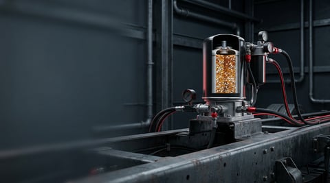
Air Dryer: Faults, Replacement & Maintenance Guide
How a truck air dryer's charge and purge cycle keeps moisture and oil out of the brake system, and what a hissing purge valve or water in the tanks means.
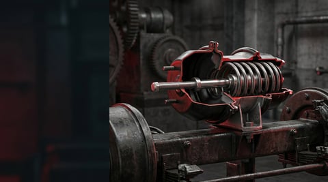
Brake Chamber: Faults, Replacement & Maintenance Guide
Service and spring brake chambers on trucks and trailers: diaphragm-leak and stroke diagnosis, why caging is mandatory before removal, and safe replacement.
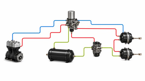
How to Read an Air Brake Diagram: Circuit Guide
How do you read an air brake system diagram? Symbol language, line colours, port codes, circuit split, trailer lines and fault-tracing, step by step.


