How to Read an Air Brake Diagram: Circuit Guide
How do you read an air brake system diagram? Symbol language, line colours, port codes, circuit split, trailer lines and fault-tracing, step by step.
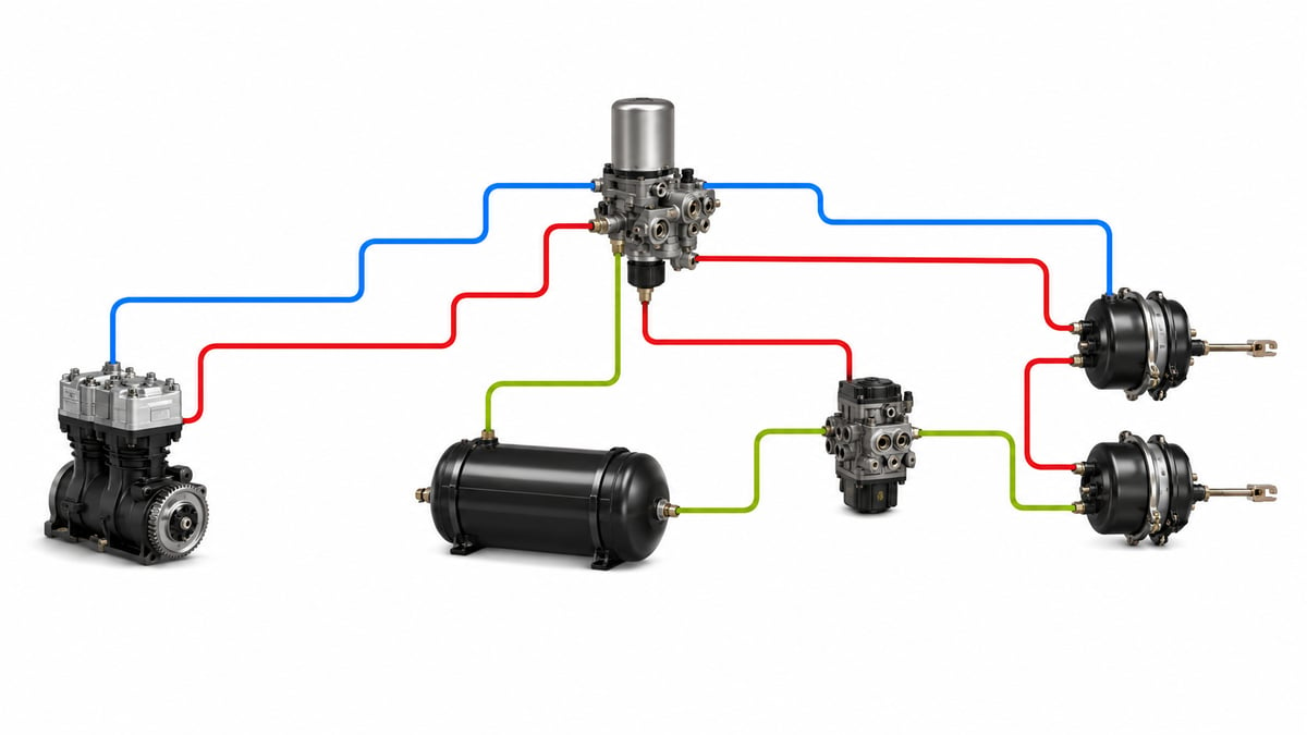
Pinned to the workshop wall is an A3 printout covered in boxes, dashed lines, small triangles and two-digit numbers. The driver's complaint is simple: "pressure keeps dropping, the gauge is down by morning even when the truck just sits there." What separates the technician who can read that printout from the one who can't shows up in the first five minutes in front of it. The one who can't read it hunts for parts he recognises scattered across the drawing and, unable to trace the line logic, starts pulling things apart. The one who can read it starts with the legend, separates the circuits, uses logic to narrow down which junction the leak has to be behind, and walks straight to a single test point. This guide does not explain how an air brake circuit works physically - it explains how to read the drawing that describes that operation: the symbol language, the line and port codes, the circuit architecture, and how to narrow down a fault from the diagram itself.
What Does a Circuit Diagram Actually Show? Diagram vs. Physical Layout
The first mistake in the field is assuming the wrong thing about the drawing in your hands. A pneumatic circuit diagram does not show where a part physically sits on the vehicle - it shows what it is functionally connected to. Just because the compressor is drawn to the left of the reservoirs on the diagram does not mean the compressor is mounted on the left side of the chassis. A diagram is not a map; it is a logic table, and the distances and angles on it are chosen purely for legibility.
For any given system there are four drawings that complement one another. The pneumatic circuit diagram shows the path air travels, the switching logic of the valves, and where the circuits split apart. The pipe routing drawing shows the physical path of the lines on the chassis, the clamp points and the pipe diameters. The component layout drawing marks where each valve is actually bolted on the chassis. The electrical wiring diagram carries the wiring for modulators, sensors and warning lamps. Chasing a leak needs the pneumatic diagram; locating a valve needs the layout drawing; tracing a wire needs the electrical diagram - using one in place of another just wastes time on the vehicle.
The pneumatic diagram also carries a silent assumption: it shows the system in one specific state. Most OE diagrams draw the system unpressurised, engine off, and with the park brake applied; the arrows inside the valve boxes belong to that state. Most complaints of "the diagram shows this port open, but on the vehicle it's closed" come from missing that assumption.
How the system behaves physically - the chain running from compressor to chamber, and the maintenance logic behind it - is covered in the air brake systems working principle guide; this article covers that same chain's counterpart on paper.
The Diagram's Symbol Language: How Valves, Reservoirs, Dryers and Chambers Are Drawn
Pneumatic diagrams use a sign language. Symbols represent a component's function, not its appearance - which is why the dryer symbol looks nothing like an actual air dryer, yet tells you what it does at a single glance.
The symbol language follows four rules. First, components that generate and store energy are drawn as enclosed volumes: the compressor is a circle with an outward-facing triangle, a reservoir is an elongated closed body. Second, valves are drawn as square boxes, and each box standing side by side represents one switching position of that valve; the arrows inside show which port flows to which, while marks resembling a "T" indicate a port that is blocked in that position. Third, how a valve is actuated is written at the edge of the box: a spring, a pedal, a lever, an electrical coil, or a pilot line arriving as a dashed line. Fourth, the line type tells you the line's job: a solid line is a working main line, a dashed line is a control line, and a dash-dot line marks an enclosure or a mechanical linkage.
| Component | Symbol logic | What to watch for when reading |
|---|---|---|
| Compressor | Circle with a solid triangle pointing outward | The engine drive connection is shown with a dash-dot line |
| Air dryer | Filter-like box with purge and regeneration ports | The regeneration reservoir sits as a separate volume |
| Check valve | A small ball seated in its seat, one-way flow | Reading the direction backwards flips the whole circuit logic |
| Double check valve | Two inlets, a ball that passes the higher pressure through | The critical junction that separates park and service pressure |
| Multi-circuit protection valve | One inlet, box with several numbered outlets | Outlet numbers match the circuit numbers |
| Foot brake valve | Two-tier box group with a pedal symbol on top | Shows the two circuits entering and leaving separately |
| Relay valve | Box with supply, control, delivery and exhaust ports | The control inlet arrives as a dashed line |
| Service brake chamber | Cylinder with a diaphragm and push rod | Single inlet; applies the brake when pressure arrives |
| Spring brake chamber | Distinct spring symbol in the park section | Applying pressure releases the brake - the logic is reversed |
| Test connection | Short stub coming off a line with a closed-port mark | A measuring point, not a service outlet |
These conventions are common practice, but the one true source is always the legend printed on the drawing in your hands. Some manufacturers combine the dryer and the regulator into a single box; others bury the relay valve inside the chamber group. When you don't recognise a symbol, going back to the legend instead of guessing is the basic discipline of reading a diagram.
Line Colours, Line Types and Port Numbers: What Do They Tell You?
The layer of the diagram that carries the most information is its lines. A line's colour tells you which circuit it belongs to, its line type tells you what job it does, and the number at its end tells you which port it connects to. Read together, even a line that looks impossible to trace by eye can be classified in seconds.
Colour coding varies from manufacturer to manufacturer and is not tied to a single mandatory international standard. Even so, a common family shows up repeatedly on European heavy-vehicle diagrams: the supply side in a neutral colour, the two service circuits in two separate colours, the park circuit in its own colour, and trailer lines drawn to match the coupling-head colours. On a black-and-white printout the colour is lost; in that case the distinction is carried by line weight, a hatching pattern, or the circuit label printed along the line.
| Line code or line type | Circuit represented | Function on the diagram |
|---|---|---|
| Solid heavy line | Main supply and working lines | Carries the air that produces braking force |
| Dashed line | Control and pilot lines | Switches a valve; carries information, not work |
| Dash-dot line | Mechanical linkage or housing boundary | Carries no air; a lever, shaft or an integrated housing |
| First service circuit colour | Usually the front-axle service brake circuit | Runs from one tier of the foot valve to the chambers |
| Second service circuit colour | Usually the rear-axle service brake circuit | Leaves the other tier and passes through a relay valve |
| Park circuit colour | Spring chamber and hand brake valve line | Brake is released when pressurised - the logic is reversed |
| Trailer supply line | Continuous air from tractor to trailer | If it's cut, the trailer brakes apply automatically |
Number codes are more reliable than colour, because they still read on a black-and-white printout and because they're also stamped on the body of the part. The common approach in heavy-vehicle pneumatics is to number ports by function: supply inlets get one digit, delivery outlets another, atmospheric exhaust its own digit, and control inlets yet another. Where a valve has more than one port of the same function, a second digit is added to tell them apart; on a valve with two delivery outlets, both share the same main digit while the sub-digit differs.
The finer detail of the numbering can vary by manufacturer and valve family. A port number read off the diagram should be checked against the number cast into the valve's own body. If the two don't match, either a different variant is fitted to the vehicle or you're holding the diagram for the wrong equipment code - either way, that has to be resolved before anything gets disassembled.
Standards and further reading
The layout a diagram encodes is not arbitrary — it follows the equipment rules for air-braked vehicles. In the United States the federal air brake standard, FMVSS 121 (49 CFR 571.121), defines the reservoirs, protection and timing a compliant system must have, which is why the same core circuits appear on almost every manufacturer drawing. For a component-by-component walkthrough of the same system away from the schematic, see the illustrated reference at airbrakecompressor.com. Always confirm port numbers and circuit splits against the specific vehicle manufacturer current diagram, since layouts vary.
Outside the United States the equivalent duties sit in national law. In the United Kingdom, regulation 18 of the Road Vehicles (Construction and Use) Regulations 1986 requires every part of the braking system to be maintained in good working order. In Canada, air brake systems fall under the Motor Vehicle Safety Regulations, which contain CMVSS 121.
How to Read an Air Brake System Diagram: A Layer-by-Layer Method
An air brake system diagram is not read start to finish, left to right. An experienced reader treats the drawing not as a single picture but as a stack of overlapping layers, following only one layer per pass. This turns a busy-looking A3 printout into manageable pieces.
The recommended reading order is as follows. First pass: the legend. Take in the colour key, line types, abbreviations and any variant footnotes. Second pass: supply. Find the compressor and trace the path from there to the dryer, the protection valve and the reservoirs as one continuous line. Third pass: circuit split. Count how many circuits leave the protection valve's outlets and follow each one separately to its reservoir, valve and chamber. Fourth pass: control lines. Follow only the dashed lines and work out which valve gets switched by which signal. Fifth pass: boundaries. Mark the trailer couplings, the test connections, the handover points to the electrical diagram, and any variant footnotes.
The Supply Circuit: Tracing the Diagram from Compressor to Reservoirs
Every air brake diagram starts at the same point: the compressor. On the diagram, the line leaving the compressor first goes to the section that regulates pressure and removes moisture. That section is made up of two or three symbols: the air dryer, the pressure regulator either built into it or drawn separately, and, in most diagrams, a small regeneration reservoir sitting right next to it.
The regulator's most instructive detail is the dashed line running back to the compressor. This pilot line unloads the compressor once system pressure reaches its upper limit, and lets it start compressing again once pressure falls to the lower limit. Without spotting that line, the question "why doesn't the compressor keep pumping" cannot be answered. The same line also triggers the dryer's purge cycle, which is why the dryer's exhaust port and muffler symbol sit right next to the regulator line.
On heavy commercial vehicles, system operating pressure sits roughly in the range of 8 to 12.5 bar, and there's a gap of a few bar between the regulator's cut-out and cut-in pressures. The exact figures vary by vehicle family, emissions level and equipment, and the OE service manual is the authority for the precise number. The diagram's job isn't to give you figures - it shows which junction controls which.
After the dryer, the line enters the multi-circuit protection valve. This is the diagram's most critical branch point and the spot where the supply pass ends. One line goes in; as many lines come out as there are circuits. This is the point to note that "everything downstream is no longer a single system - it's a set of circuits isolated from one another."
Why Is There a Two-Circuit Split, and How Does It Appear on the Diagram?
The core design principle of a heavy-vehicle brake system is that a single failure must never leave the vehicle without brakes. On paper, that translates into splitting the service brake circuit into at least two independent branches. The easiest place to see this on the diagram is how the foot brake valve is drawn: it isn't one box, it's two boxes stacked on top of each other. Each tier has its own supply inlet, outlet and exhaust; the pedal actuates both together, but their air never mixes.
The split is usually made by axle: one circuit feeds the front-axle chambers, the other the rear-axle chambers. Some applications use a diagonal or mixed split instead. Which architecture is used is read straight off the diagram - just check which chamber group the line leaving the foot valve outlet ends up at. This check is the fastest way to work out which circuit isn't doing its job when the complaint is "the brakes work, but weak."
Independence is preserved on the reservoir side too. Every service circuit has its own reservoir, and reservoirs are only ever connected to one another through the protection valve, in a controlled way. If one circuit springs a leak, the other circuit's air doesn't flow into it. On the diagram, this is shown by the protection valve's outlets carrying separate numbers and by the circuit lines never joining back up again.
For what each valve in these circuits does, its variants and its failure symptoms, the truck air brake valves guide is a detailed reference; knowing what mechanism sits behind a box makes reading the drawing noticeably easier.
Where Does the Four-Circuit Protection Valve Sit on the Diagram?
The most misunderstood component on the diagram is the multi-circuit protection valve. Because "protection" is in the name, it's often assumed to be a pressure-relief valve; in fact its job isn't to limit pressure at all, it's to isolate the circuits from one another and manage fill priority. On the diagram it sits as a box with one inlet and four or more outlets - the boundary where the supply pass ends and the circuit pass begins.
Both of its jobs can be read straight off the diagram. The first is priority: as the system fills from empty, the service brake circuits are supplied first, the park and auxiliary circuits after. The second is isolation: if one outlet loses pressure, that outlet closes off while the others hold at a defined level. On the diagram, this behaviour is shown by every outlet running down its own separate branch that never rejoins another.
| Circuit | What it feeds on the diagram | Reading if this circuit fails |
|---|---|---|
| First service circuit | Service brake chambers on one axle group | Second service and park circuit hold; stopping distance increases |
| Second service circuit | Service brake chambers on the other axle group | First service and park circuit hold; braking balance is upset |
| Park and spring chamber circuit | Hand brake valve, spring chambers, trailer control | When pressure drops, spring chambers apply on their own |
| Auxiliary consumer circuit | Suspension, doors, clutch servo, power take-off | Brake circuits are protected; only auxiliary functions are lost |
| Extra circuit (equipment-dependent) | Trailer supply or special body-builder consumers | A footnote states which equipment configuration carries it |
Reading the diagram, this table's logic boils down to one question: "Which outlet has low pressure?" The answer tells you in a single step whether the fault sits upstream or downstream of the protection valve. If every outlet is low together, the problem is on the supply side: compressor, dryer, regulator, or the valve's inlet. If only one outlet is low, the problem sits in that circuit's own branch, and the diagram gets scanned from that branch onward.
The Service Brake Circuit: Following the Line from Foot Valve to Chambers
The service brake circuit is the busiest part of the diagram, because it carries both a permanently pressurised supply line and a working line that only pressurises when the brake is applied. Telling the two apart is the key to reading this section: the line running from the reservoir to the foot valve is always pressurised; the line leaving the foot valve only pressurises when the pedal is pressed. Even though they're drawn at the same weight on the diagram, their function is different.
When the pedal is pressed, each tier of the foot valve passes the air from its own supply port straight to its own outlet. On the front-axle side, that outlet usually goes directly to the chambers. On the rear-axle side, a relay valve sits in between. The presence of a relay valve tells you a lot: the thin control line coming from the foot valve carries only information, while the air that actually fills the chambers comes the short way from a rear reservoir. The purpose is to shorten response time, and on the diagram this is made explicit by the dashed line arriving at the relay valve's control port.
The rear-axle branch often includes a load-sensing valve (brake force regulator). On mechanical versions, the dash-dot linkage arm coming from the axle is immediately recognisable; on electronic systems that function moves into the modulator and appears on the pneumatic diagram as just another box. Its job is to stop excessive braking force reaching the rear axle when the vehicle is empty. Miss this component and the complaint "the rear wheels lock up early when unladen" can never be explained.
The circuit ends at the chambers. A single-inlet diaphragm cylinder is a service brake chamber; a two-section cylinder with a spring symbol in its rear section is a combination chamber. Telling them apart matters, because a combination chamber's two separate inlets connect to two different circuits and arrive on the diagram as differently coloured lines.
How Is the Park and Spring Brake Circuit Traced on the Diagram?
The park circuit is the one section of the diagram where the logic runs backwards, which is exactly why it gets misread more than any other part. In the service circuit, pressure applies the brake; in the park circuit, pressure releases the brake. The powerful spring inside the spring chamber applies the brake mechanically, and air pressure releases it by compressing that spring. The moment you spot the spring symbol on the diagram, everything in that branch has to be read with the logic flipped.
This reversed logic is a deliberate safety design: if the park circuit loses pressure, the brake applies on its own, meaning the system fails to the safe side. Releasing a spring chamber generally takes somewhere in the range of 5 to 6 bar, though the exact threshold depends on the vehicle and chamber type and comes from the OE service manual. What matters from the diagram isn't the number - it's the behaviour: the vehicle cannot be moved until the system has filled enough.
The park branch starts at the hand brake valve. The lever symbol and detents show the driver's control positions. Graduated hand brake valves usually also have a test position, which releases the trailer's brakes while leaving only the tractor's park brake applied to check the vehicle holds - drawn as its own box on the diagram. The line leaving the valve runs to the park section of the spring chambers, usually passing through a relay valve and a double check valve along the way.
That double check valve is the most instructive junction in reading the park circuit. Its job is to stop the same chamber being loaded from both the park side and the service side at once; if the pedal is pressed while the park brake is applied, spring force and air force would add together and overload the chamber and mechanism beyond their design limit. Wherever you see the two-inlet ball symbol, know that junction works on the logic of "let only the larger of the two forces through."
How Are Trailer Connection Lines and Coupling Colours Shown on the Diagram?
On the right-hand edge of the tractor's diagram sit the detachable coupling symbols, drawn as two half-circles. These are the trailer coupling heads, and this is where the diagram is saying "the system doesn't end here - there's a second diagram on the other side." There are two air lines between tractor and trailer, and their functions are entirely different.
The supply line sends continuous air to the trailer and fills the trailer's own reservoir. The control line only pressurises when the brake is applied and carries the "how hard to brake" signal to the trailer. In European practice the supply coupling is colour-coded red and the control coupling yellow; in North American practice the supply is red and the service control line is blue. On the diagram these colours match the line colours used elsewhere.
| Line | Coupling code and function | Behaviour read from the diagram if the line is cut |
|---|---|---|
| Trailer supply line | Red in European practice; fills the trailer's reservoir | Pressure is lost, and the trailer brakes under emergency logic |
| Trailer control line | Yellow in European practice; carries the brake command | Trailer service brake gets no command; the load pulls on the tractor |
| Trailer park and emergency circuit | Managed through the trailer's own park relay valve | When supply is lost, the trailer's spring chambers apply |
| Electrical connector | Carries ABS and lighting signals; not pneumatic | Traced on the electrical diagram, not the pneumatic one |
On the tractor side, the component managing these two lines is the trailer control valve. On the diagram it appears as a box with several inlets: one control input from each of the two service circuits, plus one input from the park circuit. These three inputs together explain that the trailer can be braked by the foot valve, by the hand brake, and by whichever service circuit is still working if the other has failed.
The most important safety logic on the whole diagram is hidden here: cutting the supply line applies the trailer brakes. If a coupling comes apart or a hose bursts and supply pressure drops, the park relay valve on the trailer dumps the spring chambers. This behaviour is visible on the diagram, because the trailer-side relay valve's control input is connected to the supply line. Anyone unfamiliar with this junction cannot answer "the supply hose snapped - why did the trailer lock up?"
Tractor and trailer diagrams are separate documents, used together when tracing a fault. The fastest field split comes straight from this: disconnect the trailer, and if the leak is still there, the problem is on the trailer side; if it stops, it's on the tractor side. That single move cuts the area you need to scan in half.
ABS and EBS: How Does the Electronic Layer Enter the Pneumatic Diagram?
On modern vehicles the pneumatic diagram alone isn't enough, because air's path is now partly decided electronically. This layer shows up on the diagram in two forms: modulator boxes and handover marks to the electrical diagram. A modulator is drawn like an ordinary valve with supply, delivery and exhaust ports; the difference is that its control comes in via an electrical symbol rather than a dashed pilot line.
On an ABS application, the pneumatic architecture is largely unchanged: modulators sit on top of the existing lines and only intervene during wheel lock-up, which is why an ABS diagram looks very similar to its non-ABS counterpart. On an EBS application, the architecture changes: the brake command is primarily carried electrically, with the pneumatic line held in reserve as a backup path. The way to tell them apart is to look at what the lines leaving the foot valve actually do.
The most important consequence of the electronic layer is this: a line that looks correct on the pneumatic diagram may not behave as expected if there's a fault on the electronic side. A modulator cutting off pressure isn't a pneumatic defect - it can be a deliberate electronic decision. That's why, on EBS-equipped vehicles, reading the diagram is always carried out together with reading the fault codes.
Fault-Tracing from the Diagram: Where Do You Start with Low Pressure?
This is where reading a diagram actually pays off. With a low-pressure complaint, the goal isn't to find the leak first - it's to narrow down the area where the leak can be. The diagram does this by breaking the system into junctions: every valve, every reservoir and every coupling is a junction, and every junction is a measurable boundary. The sequence below is adapted to the specific vehicle and equipment, and the safety procedure set out in the OE service manual applies at every step.
- Pin down the complaint: on which gauge, on which circuit, over how long, and under what condition does pressure drop? While parked, when braking, or when the park brake is applied? These answers narrow the search area from the very first step.
- Confirm the diagram you're holding actually matches the vehicle. Compare the chassis and equipment code, the variant footnotes in the header, and the numbers on the valves actually fitted; tracing a fault with the wrong diagram is wrong from the start.
- Read the legend and mark the supply line from end to end with a pen. The path between compressor, dryer, regulator and protection valve should become visible as a single chain.
- Fill the system and watch all the gauges together. Do all circuits drop together, or only one? This single observation tells you whether the fault sits upstream or downstream of the protection valve and rules out half the diagram.
- Mark the test connections on the diagram and look for the boundary junction: the section between the last point where pressure is still correct and the first point where it's low is where the leak has to be.
- Disconnect the trailer and repeat the measurement. If the leak is still there, the search moves to the trailer diagram; if it's gone, it stays on the tractor diagram. This step is usually the single move that pays off the most.
- Listen and look at the valves' exhaust ports. An exhaust port bleeding air continuously tells you which valve the leak is inside; the search ends at whichever valve that exhaust belongs to on the diagram.
- Test the park circuit separately. Cycle the hand brake valve through its detents and watch the behaviour on the spring chamber line; a leak in the park branch can distort the total drop enough to mislead the service circuit measurements.
- Before disassembling the junction you've found, confirm it on the diagram: does that junction actually feed the circuit where the complaint occurs? Disassembly without confirming the circuit match often creates a second fault.
- After the repair, repeat the same measurement at the same test points and log the results against the junction's name from the diagram. That record saves having to scan from scratch the next time a fault occurs.
The strength of this method is that no step leaves room for guessing: each step turns a junction read from the diagram into a measurable boundary, and every measurement shrinks the search area. Used together with the air brake fault diagnosis guide, which scans fault causes and fixes from a symptom-first angle, diagram tracing quickly ties a symptom list back to a physical junction.
Why Do Manufacturer Diagrams Differ, and Why Does the OE Diagram Take Precedence?
Air brake diagrams found in general training material are valuable for learning, but they cannot be used on their own in the field. The reason is that the same basic architecture is implemented differently by every manufacturer, and those differences lead directly to misdiagnosis.
The first difference is drawing convention: one manufacturer draws the supply line at the top, another at the bottom; one separates circuits by colour, another by number; one draws the relay valve as its own symbol, another buries it inside the chamber group. The second difference is component choice: the same function is performed by a standalone valve on one vehicle and an integrated module on another. The third and most dangerous difference is equipment variants: the same model vehicle can have different diagrams depending on body type, axle configuration, suspension type and market.
Which is why there's only one valid test for choosing a diagram: the diagram must match the vehicle's chassis and equipment code. Being the same make and model isn't enough - tracing a fault without confirming that match means following the right method on the wrong map. General diagrams are for learning the system; the OE diagram is for doing the work. Currency matters too: manufacturers issue component changes through service bulletins. If the valve number on the vehicle doesn't match the number on the diagram, the vehicle is right and the printout is wrong.
Common Misreadings When Reading Diagrams in the Field
Most diagram-reading mistakes don't come from a lack of knowledge - they come from an assumption nobody noticed they were making. The ones below are the most frequently repeated on the shop floor, and each one costs measurable time.
- Mistaking the diagram for a layout map: Position and direction on the drawing don't show physical placement; you need the layout drawing to actually locate a valve.
- Mistaking a valve box for a physical compartment: Boxes sitting side by side are not chambers - they are switching positions; three boxes mean three positions.
- Missing which state the drawing depicts: Most diagrams show the system unpressurised with the park brake applied; without knowing that, positions get misread.
- Mistaking a dashed line for a main line: Control lines are low-flow information paths; expecting high flow from one gets a healthy system misdiagnosed as faulty.
- Reading the park circuit with normal logic: Pressure releases the brake on the spring chamber line; miss that reversed logic and the whole park circuit gets misread.
- Mixing up the trailer lines: Supply is continuous, control only pressurises when braking; confusing the two flips how trailer behaviour is read.
- Using another manufacturer's diagram: Differences in symbol and colour convention can make even a correctly read diagram get applied to the wrong vehicle.
- Ignoring the electronic layer: On an EBS- or ABS-equipped vehicle, a line that looks pneumatically correct can still behave differently because of an electronic decision.
What all these mistakes have in common is haste. Reading the legend, scanning the footnotes and marking the diagram layer by layer takes a total of a few minutes; skip it and the time lost is measured in hours. Reading a diagram isn't a talent - it's a discipline with a defined order.
Finally, the diagram's limits need to be understood. A diagram tells you how the system is built and how it's supposed to behave - it doesn't tell you what a part is actually doing right now. A worn seal, a clogged muffler or a fatigued spring don't show up on the diagram. That's why diagram tracing always runs alongside measurement: the drawing narrows the search area, the measurement makes the call. In every case, the current OE circuit diagram and service manual for the vehicle's chassis and equipment code remain the authority.
Air brake system diagram: the air path in order
An air brake system diagram is easiest to read as a path rather than a picture. Air is drawn in through a filter, compressed by the engine-driven compressor, dried and cleaned in the air dryer, then stored in the reservoirs. From the reservoirs a multi-circuit protection valve divides the supply into separate circuits so that a leak in one cannot empty the others. Driver demand enters at the foot brake valve, is amplified locally by relay valves, and finally reaches the brake chambers where pressure becomes mechanical force. Spring brake chambers sit in the same path but work in reverse: they need air to stay released.
| Stage | Component | What happens here |
|---|---|---|
| 1 | Air filter and compressor | Ambient air is filtered and compressed by the engine |
| 2 | Governor | Charging stops at cut-out pressure and restarts at cut-in |
| 3 | Air dryer | Moisture and oil are removed; the cartridge is purged and regenerated |
| 4 | Wet and service reservoirs | Dry air is stored for the service and park circuits |
| 5 | Multi-circuit protection valve | Supply is split so one circuit failure cannot drain the rest |
| 6 | Foot brake valve | Driver demand is metered into the service circuits |
| 7 | Relay valve | Reservoir air is admitted locally to shorten response time |
| 8 | ABS modulator | Pressure is held, released or reapplied to prevent wheel lock |
| 9 | Service brake chamber | Air pressure becomes push-rod force at the wheel |
| 10 | Spring brake chamber | Spring applies the park brake; air is required to hold it off |
Dual-circuit layout: why the system is split
Heavy vehicles do not run a single brake circuit. The supply is divided so that the front axle, the rear axle, the park and trailer supply, and the auxiliary consumers each draw from a protected branch. If one branch develops a leak, the protection valve isolates it and the remaining circuits keep enough pressure to stop the vehicle. On a tractor and trailer combination the coupling adds two lines — supply and control — plus the electrical connection that carries ABS or EBS signalling. Reading any air brake diagram therefore starts with identifying which circuit each line belongs to, not with the individual valves.
Shop this part: Brake System
Tags
Frequently Asked Questions
- How do you read an air brake system diagram, and where do you start?
- Read it layer by layer, not left to right. Start with the legend: colour key, line types and any variant footnotes. Then trace the supply layer - compressor to dryer, on to the multi-circuit protection valve and the reservoirs - as one continuous chain. On the third pass, separate the circuits leaving the protection valve's outlets one by one; on the fourth pass, follow only the dashed lines, meaning the control lines; on the last pass, mark the trailer couplings, the test connections and the handover points to the electrical diagram. After these five passes you're left with a supply map, a circuit map and a control map, and fault-tracing runs on those three.
- What do the line colours and numbers on the diagram mean?
- Colour tells you which circuit a line belongs to, line type tells you what job it does, and the number at its end tells you which port it connects to. A solid heavy line is a working main line, a dashed line is a low-flow control line, and a dash-dot line is a mechanical linkage that carries no air. Colour coding isn't tied to one mandatory international standard and varies by manufacturer; supply, the two service circuits, the park circuit and the trailer lines are usually drawn in separate colours. Port numbers are more reliable than colour because they still read on a black-and-white printout and are also stamped on the valve's own body.
- How do you read valve symbols on a brake diagram?
- Valves are drawn as square boxes, and each box sitting side by side is one switching position of that valve - three boxes mean three positions, not three physical chambers. The arrows inside show which port flows to which, and a mark resembling a T shows a port that's blocked in that position. How the valve is actuated is written at the box's edge: a spring, a pedal, a lever, an electrical coil, or a pilot line arriving as a dashed line. Mistaking the boxes for physical compartments inside the valve is the single most common reading error.
- Where does the four-circuit protection valve sit on the diagram, and what does it do?
- It sits as a box with one inlet and four or more numbered outlets, right at the boundary where the supply pass ends and the circuit pass begins. Despite the name, its job isn't limiting pressure - it isolates the circuits from each other and manages fill priority: service brake circuits fill first as the system comes up from empty, park and auxiliary circuits after. If one outlet loses pressure, it closes off on its own while the others hold at a defined level. On the diagram, that's shown by every outlet running down its own branch that never rejoins another.
- If one circuit fails, how do you tell from the diagram which circuit stays working?
- By following the protection valve's outlets. If one service circuit fails, the other service circuit and the park circuit stay working - stopping distance increases and balance shifts, but the vehicle isn't left without brakes. If the park circuit loses pressure, the spring chambers apply on their own, because pressure releases the brake in that circuit. If the auxiliary circuit fails, the brake circuits stay protected and only functions like suspension or the clutch servo are lost. If every outlet drops together, the fault sits upstream of the protection valve - in the compressor, dryer or regulator.
- How do you tell the trailer supply line from the control line on the diagram?
- Both end at the two half-circle coupling symbols on the tractor diagram's right edge, but their function differs. The supply line sends continuous air to the trailer and fills its reservoir; the control line only pressurises when the brake is applied and carries the braking-force signal. In European practice the supply coupling is red and the control coupling yellow; in North American practice supply is red and the service control line is blue. If the supply line is cut, the park relay valve on the trailer dumps the spring chambers and the trailer brakes on its own.
- Why is the park and spring brake circuit read backwards on the diagram?
- Because in the service circuit pressure applies the brake, while in the park circuit pressure releases it. The spring inside the spring chamber applies the brake mechanically; air pressure compresses that spring to release it. The moment the spring symbol appears on the diagram, the whole branch has to be read with the logic flipped. This is a deliberate safety design: if pressure is lost, the brake applies on its own. Because the chamber still holds very high spring force even with the air released, work on it must always follow the OE release procedure with the vehicle chocked.
- Where do you start on the diagram when air pressure is low?
- First pin down the complaint - which gauge, which circuit, under what condition. Then fill the system and watch every gauge together: if all circuits drop together, the fault is upstream of the protection valve; if only one drops, it's in that circuit's own branch. That single check eliminates half the diagram. Next, use the test connections marked on the diagram to find the boundary junction between the last point still reading correct pressure and the first point reading low - that section is where the leak has to be. Disconnecting the trailer and repeating the measurement is usually the single move that pays off the most.
- Can a generic diagram found online be used on the vehicle?
- For learning, yes; for doing the work, no. The same basic architecture is drawn differently by every manufacturer: one puts the supply line at the top, another at the bottom; one separates circuits by colour, another by number; one draws the relay valve separately, another buries it in the chamber group. More dangerous still are equipment variants - the same model can carry different diagrams depending on body type, axle layout and market. A diagram has to match the vehicle's chassis and equipment code. If the valve number on the vehicle doesn't match the diagram, the vehicle is right and the printout is wrong - go back to the current OE document.
- What are the most common mistakes when reading diagrams in the field?
- The most common is treating the diagram as a layout map - position and direction on the drawing don't show physical placement on the vehicle. Second is missing which state the drawing depicts: most OE diagrams show the system unpressurised with the park brake applied. Third is mistaking a dashed control line for a main line, which carries low flow by design. Fourth is reading the park circuit with normal, non-reversed logic. Fifth is mistaking a test connection for a service outlet. Ignoring the electronic layer is also a mistake: on an EBS- or ABS-equipped vehicle, a pneumatically correct-looking line can still behave differently because of an electronic decision.
Related Articles

Air Dryer: Faults, Replacement & Maintenance Guide
How a truck air dryer's charge and purge cycle keeps moisture and oil out of the brake system, and what a hissing purge valve or water in the tanks means.
Brake Chamber: Faults, Replacement & Maintenance Guide
Service and spring brake chambers on trucks and trailers: diaphragm-leak and stroke diagnosis, why caging is mandatory before removal, and safe replacement.

Air Brake Chamber Explained: Types, Sizes, Failure Symptoms & Replacement
Truck and trailer inspection reports rarely say the brake chamber is defective; they report brake force imbalance. Chamber types, sizes, symptoms and replacement.


