ABS Wheel Speed Sensor & ECU: Faults, Replacement & Care
Diagnose, replace and maintain the ABS wheel speed sensor, tone ring and ECU on heavy commercial vehicles: symptoms, air gap, testing and fault codes.
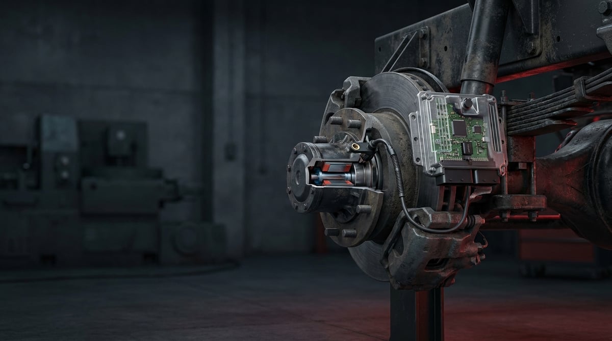
When the amber ABS light comes on in the dash of a tractor unit, most drivers say "the brakes still bite, I'll keep going." But with ABS disabled, the wheels lock under hard braking, the trailer can jackknife and the stopping distance grows noticeably. On a heavy commercial vehicle, the name for that difference is the gap between a crash and a controlled stop. This guide explains the trio of the ABS wheel speed sensor, the tone ring and the ECU/module in language that comes straight from the workshop floor; it walks through failure symptoms, air gap setting, measurement methods and replacement steps in order.
E-E-A-T note: This document was prepared by the VADEN technical team, which works on heavy commercial vehicle braking and electronic systems. The values here are for general reference; for exact figures such as air gap, resistance and torque, always rely on the current OE service manual of the vehicle/axle manufacturer. Last updated: September 2026.
Heavy commercial vehicle air brake systems are designed within the framework of ECE R13 (UN/EU braking regulation) and ISO 611.What Are the ABS Wheel Speed Sensor and ECU? Function and Working Principle
The ABS wheel speed sensor is an electronic measurement and control system that converts the rotational speed of each wheel into an electrical signal and passes it to the ABS/EBS module (ECU); the ECU then uses this information to adjust brake pressure wheel by wheel, preventing lock-up.
The heart of the system is three parts: the speed sensor positioned close to the wheel hub, the toothed ring that turns with the wheel (tone ring / tone wheel / pulse wheel) and the ECU/ABS module that processes the signals from all wheels. As the teeth of the tone ring pass in front of the sensor, the sensor produces hundreds of pulses per second. As the pulse frequency rises the ECU understands the wheel is accelerating, and when it drops suddenly it understands that wheel is starting to lock; it then releases and reapplies the pressure to the relevant brake chamber via the modulator valves within fractions of a second.
On a heavy commercial vehicle this system is often intertwined with EBS (Electronic Braking System). Modules of the Knorr-Bremse, Wabco (ZF) or Bendix type manage not only ABS but also ASR (traction control), hill-start assist and retarder integration. When the sensor data is corrupted, not only ABS but also these auxiliary functions can be disabled.
- Speed sensor: A probe that converts changes in the magnetic field into an electrical signal, usually fixed to the hub with a clamping bush.
- Tone ring (toothed ring): A toothed metal ring pressed onto the axle hub or spindle; it determines the pulse count.
- Sensor cable and connector: The point most exposed to vibration and water; most corrosion and chafing failures occur here.
- ECU / ABS-EBS module: The brain that processes the signals, generates fault codes and drives the modulator valves.
How Does a Passive (Inductive) Sensor Work?
A passive sensor is a simple structure containing a permanent magnet and a coil; it needs no external supply. As the tone ring teeth pass, the magnetic field changes and an alternating (AC) voltage is generated in the coil. The signal amplitude depends on wheel speed: at low speed the voltage is weak, which is why a passive sensor can go "blind" at very low speeds. It is still widespread on the majority of heavy commercial vehicles because of its durability.
How Does an Active Sensor Work?
An active sensor (Hall effect or magneto-resistive) draws a supply from the ECU and its output is a square wave (digital) signal of constant amplitude that does not depend on speed. It can take a reading even at very low speed, indeed at speeds close to zero; this is why it is preferred in hill-start and precise ASR applications. Active sensors generally work with a magnetically coded ring (encoder ring) and can be more sensitive to contamination than the inductive type.
Processing the Signal in the ECU
The ECU continuously compares the signals from four (or more, in a 6x2/6x4 configuration) wheels. If one wheel's speed deviates abnormally from the others, it interprets this as a cable break, a disturbed air gap or tone ring damage; it writes the relevant fault code (DTC) to memory and, if necessary, partially or fully disables ABS.
| Feature | Passive / Inductive Sensor | Active Sensor (Hall/MR) |
|---|---|---|
| Supply | Not required (self-generating) | Supply from ECU required |
| Signal type | Analog AC (sine) | Digital square wave |
| Low-speed reading | Weak / limited | Very good (close to zero) |
| Measurement | Resistance (ohm) + AC voltage | Resistance measurement mostly meaningless; check signal/current |
| Typical use | Classic heavy commercial ABS | Modern EBS, ASR, hill-start |
| Sensitivity to contamination | Medium | Can be high on the coded ring |
Part-number verification: The front and rear axles of the same tractor unit may use different sensor lengths, connector types and signal architectures (passive/active). Do not fit a sensor just because it looks like the old one removed from the hub; confirm it with the vehicle chassis number and the OE part reference. The wrong type of sensor causes ABS to never engage at all.
Failure Symptoms and Diagnosis
ABS sensor failures rarely arrive suddenly as "everything stopped"; most often they begin as signals that appear under certain conditions and then disappear. The table below summarizes the symptoms most frequently encountered in the field, their possible causes and the verification method.
| Symptom | Possible Cause | Check / Verification |
|---|---|---|
| ABS warning light on continuously | Sensor open circuit, broken cable, damaged tone ring | Read DTC with a diagnostic tool; identify the relevant wheel, measure resistance/signal |
| ABS light on only while moving | Excessive air gap, broken tone ring tooth, loose sensor | Check sensor seating and air gap; turn the wheel and watch live data |
| Single wheel locks / vibrates at a certain speed | Intermittent signal, contaminated sensor tip, occasional loss of contact | Watch the waveform with an oscilloscope; look for signal loss while moving the cable |
| ASR/traction control or hill-start not working | One axle sensor giving a weak signal | Compare all wheel speeds in live data; find the deviating wheel |
| Vehicle pulls, does not track straight during braking | ABS disabled on one wheel, active on the others | Test drive + DTC; identify the disabled wheel |
| Intermittent ABS fault, returns after clearing | Connector corrosion, cable crack, hub play (bearing) | Open and clean the connector; rock the wheel to check bearing play |
| Fault appearing in cold/rain, disappearing when dry | Water ingress into the connector, crack in cable insulation | Inspect connector sealing and cable routing visually + test by measuring |
Reading Diagnostics (DTC)
The first step is always to read the fault code. Modern EBS modules report separately which wheel (e.g. "front left", "rear right") and what kind of fault (open circuit, short circuit, no signal, implausible signal) is present. An "implausible signal" code is usually a sign not of the sensor but of the air gap or tone ring; replacing the sensor without making this distinction is a common waste.
Comparing Wheels with Live Data
Lift the vehicle and rotate the wheels by hand or at idle, then compare the speed values of the four wheels on the diagnostic tool's live data screen. In a healthy system the values rise and fall close to one another. If one wheel's value jumps, resets or lags behind the others, the problem is on that line.
Waveform Analysis with an Oscilloscope
The most precise method is the oscilloscope. On a passive sensor, a smooth, symmetrical sine wave is expected while the wheel is turned; sudden drops in amplitude indicate damage to a tone ring tooth or a variable air gap. On an active sensor, a clean square wave with clear low-high transitions should be seen. Distortion of the wave while moving the cable by hand is definitive proof of a broken/intermittent contact fault.
Standards and further reading
This subject is governed by the equipment rules for air-braked commercial vehicles. In the United States the federal air brake standard, FMVSS 121 (49 CFR 571.121) defines the reservoirs, protection and timing a compliant system must provide, and Europe applies the equivalent limits of UNECE Regulation No. 13. For further detail, see the illustrated reference guide at airbrakecompressor.com. Always confirm specific figures against the current regulation and the vehicle manufacturer service data.
Outside the United States the equivalent duties sit in national law. In the United Kingdom, regulation 18 of the Road Vehicles (Construction and Use) Regulations 1986 requires every part of the braking system to be maintained in good working order. In Canada, air brake systems fall under the Motor Vehicle Safety Regulations, which contain CMVSS 121.
Replacement / Installation Steps
Personal protective equipment and safety (PPE): Before starting, secure the vehicle on level ground, chock it and bring the air pressure down to a safe level. Switch off the ABS/EBS supply contact during lifting; disconnecting a connector on a live circuit can cause a fault entry in the module. Use gloves and safety goggles; when working around the brake system, watch out for residual pressure in the chambers and valves.
- Verify the fault: Before removing the sensor, read the DTC and confirm which wheel is responsible; avoid unnecessary disassembly.
- Cut the contact and supply: Switch off the system to protect the ABS module from a false entry, and chock the vehicle.
- Lift the wheel and gain access: Raise the relevant wheel off the ground, remove the rim if needed; reach the sensor and cable route.
- Disconnect the connector: Carefully release the sensor connector from its lock; do not force and break the clip, and note any corrosion.
- Remove the old sensor: On the clamping-bush type, the sensor is pulled out with a slight twist; if it is seized, turn it free with pliers, do not force the bore.
- Clean the seat and tone ring: Clean the rust and dirt in the sensor seat; visually inspect the tone ring teeth, and if there is a broken/packed tooth, renew the ring as well.
- Fit a new clamping bush: In most applications a new clamping bush is used together with the sensor; this ensures the sensor seats tightly at the correct distance from the tone ring.
- Prepare the sensor tip: A thin grease/paste recommended by the manufacturer may be applied to the sensor head (refer to the OE manual); do not scratch the tip and keep it clean.
- Push the sensor fully home: Push the sensor into the seat until it touches the tone ring. In many designs the air gap sets itself automatically on the first wheel rotation; on types that require a separate measurement, check the air gap.
- Route the cable correctly: Run the cable through its original clamps; keep it away from rotating/moving parts, the exhaust and sharp edges. Lock the connector fully.
- Clear, test and road-test: Clear the fault memory with the diagnostic tool, verify wheel speed in live data; with a controlled test drive at low speed, confirm that the ABS light stays off.
Points to Watch (Common Mistakes)
The most common mistake: working by the symptom rather than the code. Randomly replacing sensors because "the ABS light is on" is a widespread waste of time and money. Much of the problem is not in the sensor; it is in the air gap, the tone ring tooth, connector corrosion or hub bearing play. Read first, then remove.
Do not overlook the hub bearing: A worn wheel bearing changes the distance between the tone ring and the sensor during rotation and produces an "intermittent signal" fault. If the fault persists even though the sensor has just been fitted, check the bearing play.
- Fitting a sensor of the wrong length/type — the sensor seats but no signal ever arrives.
- Forgetting to push the sensor onto the tone ring; leaving too much air gap.
- Not locking the connector fully, or refitting a water-soaked connector without cleaning it.
- Replacing only the sensor without seeing the crack/mud packing in a tone ring tooth.
- Routing the cable near a rotating part or a hot surface — it soon chafes through and breaks.
- Trying to judge "good/faulty" by measuring resistance on an active sensor; on the active type the correct method is checking signal/supply.
- Going on a test drive without clearing the fault memory; misreading the result because of an old entry.
Technical Values and Check Points
The values below are typical/general reference ranges commonly encountered on heavy commercial vehicles; the exact value varies by vehicle, axle and sensor type, and the OE service manual is always authoritative.
| Parameter | Typical / General Reference | Note |
|---|---|---|
| Passive sensor coil resistance | ~ 1,000 – 2,500 ohm | Varies by type; use the OE value as the basis |
| Air gap | ~ 0.1 – 1.5 mm | Most types self-seat; for types requiring measurement, refer to the manual |
| AC output at test speed (passive) | starting at a few hundred mV when turned by hand and rising | Amplitude should rise quickly; if low/flat there is a problem |
| Insulation (sensor – chassis/ground) | very high (open circuit in practice) | Low value = cable/body leakage |
| Connector pin resistance | negligible (≈ 0 ohm) | High resistance = corrosion/looseness |
| Operating temperature range | approximately −40 °C to +150 °C | Must withstand the high temperature near the brake |
Torque values at the sensor mounting and surrounding connections are also general reference; for the exact value the manufacturer's manual is authoritative:
| Connection | Typical Torque (general reference) |
|---|---|
| Sensor holder / bracket bolt (M6) | ~ 6 – 9 Nm |
| Sensor holder / bracket bolt (M8) | ~ 15 – 25 Nm |
| Cable clamp/clip connections | hand-tight + clamp lock (no torque required) |
Field tip: If the sensor resistance is borderline, repeat the measurement while moving the sensor and flexing the cable. If the value stays steady the sensor is probably sound; if it jumps when moved, there is a break inside the cable/connector.
- Is there a broken, dented tooth or mud/rust packing on the tone ring teeth — check by eye and by hand.
- Is the sensor tip seated enough to touch the tone ring, or is it loose?
- Is there green corrosion, a water mark or a loose pin inside the connector?
- Is there any sign of chafing, crushing or heat damage along the cable route?
- Is there any perceptible play in the wheel bearing (it disturbs the sensor distance)?
- Does the same code return after clearing, or has it cleared?
Maintenance and Service Life
The ABS wheel speed sensor is not a scheduled-replacement part; it runs until a fault appears. However, its life depends directly on the environmental conditions it is exposed to. Heavy mud, salt, road chemicals and constant vibration shorten the life of the sensor and especially the cable-connector assembly. For this reason the goal in regular maintenance is to keep the environmental conditions under control, not the sensor itself.
- At every brake service, visually inspect the sensor cable and connector; look for chafing and looseness.
- Clean the tone ring area with compressed air/a dry brush; do not direct high-pressure water straight at the sensor tip.
- Make sure the connectors are locked and dry; apply suitable sealing to a connector that has taken on water.
- During hub/bearing maintenance, verify that the sensor distance is preserved.
- If there is a recurring fault on one sensor line, evaluate the cable and connector together with the sensor as a whole.
- When working on the axle (bearing, brake, hub), protect the sensor from contamination and impact; if removed, refit it clean.
With the correct type of sensor, sound wiring and a properly seated tone ring, the ABS system runs trouble-free for years. What matters is not putting off the warning light as "I'll look at it later"; even though the vehicle seems to brake while ABS is disabled, the safety margin has narrowed seriously.
When the ABS wheel speed sensor, tone ring and ECU work soundly, your heavy commercial vehicle keeps to the road at every braking. For the front and rear axle applications of heavy commercial vehicles, VADEN ORIGINAL produces the ABS sensor ring and the ABS sensor holder to OE dimensions, together with the ABS solenoid modulator valve and repair kits for the ABS solenoid modulator valve, the ABS double relay valve and the ABS electronic control unit. With the right part choice and the diagnosis-and-replacement steps in this guide, you can switch off the ABS warning light for good.
Shop this part: ABS Sensor
Related categories: ABS Sensor · Sensor Ring · Sensor Holder · ABS Solenoid Modulator Valve · ABS Electronic Control Unit · Repair Kit
Related technical guides: Brake Caliper Overhaul Kit: Guide Pins, Boots & Adjuster · Air Processing Unit (APU/EAC): Faults, Replacement & Care · Pressure Limiting Valve: Faults, Replacement & Maintenance · Four-Circuit Protection Valve: Faults, Diagnosis & Replacement · ALB Load Sensing Valve: Faults, Replacement & Setting Guide
Application and compatibility: Vehicle compatibility catalogue · Engine compatibility catalogue
Main guide: ABS Brake System: How It Works, Warning Light and Faults
Tags
Frequently Asked Questions
- The ABS light is on but the brakes still bite — can I keep driving?
- It will stop the vehicle over a short distance, but ABS is disabled; under hard braking the wheels lock, the trailer can jackknife and the stopping distance grows. You need to have the fault read and fixed as soon as possible; the risk is especially high on wet/slippery roads.
- Does a single sensor failure disable the entire ABS?
- On most heavy commercial systems, a sensor fault on one wheel can, for safety reasons, cause that axle's or the entire ABS/ASR function to be disabled. To avoid risking a wheel it "cannot be sure of", the system shuts off ABS; this is why even a single sensor must be taken seriously.
- I replaced the sensor but the ABS light is still on — why?
- The most common reasons: the fault memory was not cleared, the wrong type/length of sensor was fitted, the tone ring tooth is damaged, the connector is corroded or there is hub bearing play. First clear the DTC and read it again; if the code still points to the same wheel, check the tone ring and the bearing.
- Do I need to set the air gap by hand?
- In many modern designs the sensor is pushed fully into its seat and the gap sets itself on the first wheel rotation. On some types measurement with a feeler gauge is required. The correct method depends on the vehicle/axle type; refer to the OE service manual.
- How do I tell a passive from an active sensor, and are they interchangeable?
- A passive sensor is two-wire and produces a signal without any supply; an active sensor is supplied and gives a digital signal. The two are electrically different, and whichever one the ECU architecture expects must be fitted; arbitrary swapping causes the system to stop working.
- How do I check whether the sensor is sound with a multimeter?
- On a passive sensor you can measure the resistance and see whether it falls within the OE reference range, then turn the wheel to check AC voltage generation. On an active sensor a resistance measurement usually gives no meaningful result; the supply and signal are checked, preferably with an oscilloscope.
- Does the tone ring (toothed ring) also need replacing, or is the sensor alone enough?
- If there is a crack, denting or mud/rust packing on a tone ring tooth, replacing the sensor alone does not solve the problem. When the teeth are irregular the signal stays distorted; in that case the tone ring must also be renewed. Since the ring is mostly pressed onto the hub/spindle, the labour must be planned separately.
- Can the sensor cable be spliced and repaired when it breaks?
- Although a temporary fix may seem possible, the ABS sensor line carries a low-level, sensitive signal; a poor splice increases the risk of corrosion and intermittent contact. The soundest option is to replace the sensor complete with its cable/connector using a genuine equivalent part.
- The diagnostic tool reports an "implausible signal" code — should I just replace the sensor?
- No. That code usually points not to the sensor itself but to the air gap or the tone ring. Modern EBS modules report separately which wheel is affected and what kind of fault it is: open circuit, short circuit, no signal or implausible signal. First check whether the sensor is seated fully, inspect the tone ring teeth and check hub bearing play; swapping the sensor without making that distinction is a common waste.
- Can I pressure-wash around the sensor when I clean the vehicle?
- Do not direct high-pressure water straight at the sensor tip; clean the tone ring area with compressed air or a dry brush instead. Pressurised water works its way into the connector and creates corrosion and intermittent-contact faults. Make sure the connectors are locked and dry, and apply suitable sealing to any connector that has taken on water. Sensor life depends largely on keeping mud, salt and moisture away.
Related Articles

ABS Brake System: How It Works, Warning Light and Faults
Learn how the ABS brake system works on heavy trucks, why the warning light comes on, how to diagnose sensor faults, and the correct replacement steps.
Brake Chamber, Diaphragm & Hose: Faults, Replacement, Care
Learn how to spot a leaking brake chamber, measure push rod stroke, cage the power spring safely and replace the unit and hose without risk on heavy trucks.
Air Dryer Purge Valve: Faults, Replacement and Maintenance
How a truck air dryer purge valve works, spotting leak and freezing symptoms, safe step-by-step replacement and keeping the air brake system dry.


