Feed Pump & Hand Primer: Faults, Replacement, Maintenance
Truck feed pump and hand primer guide: how they work, fault symptoms, low pressure diagnosis, replacement steps, torque values, bleeding and maintenance tips.
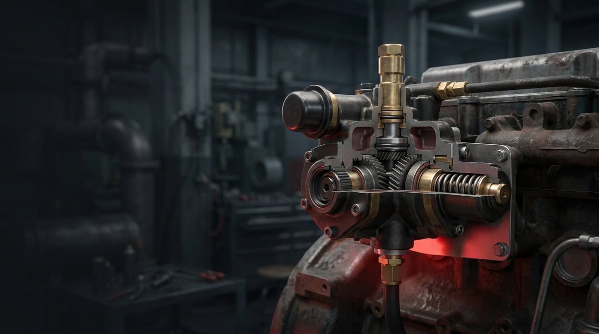
At the crack of dawn the starter is engaged, the engine turns over a few times and dies. The driver opens the hood and starts working the hand primer; after a few strokes the truck fires up and the day is saved. In the heavy commercial vehicle world this scene is so familiar that most people shrug it off with "well, the fuel is getting through". Yet an engine that only starts after hand priming is already telling you something is wrong: the system cannot hold fuel pressure on its own, it is drawing air somewhere, or the feed pump is about to die. This guide covers the feed pump (fuel transfer pump) and the hand primer (priming pump) assembly mounted on it in plain workshop language — what it does, how it fails, how to diagnose it, how to replace it and how to extend its service life.
E-E-A-T note: This document was prepared by the VADEN technical team, based on field and product experience with heavy commercial vehicle fuel systems. The values given here are typical reference ranges; they vary with engine family, pump type and year of manufacture. For exact torque, pressure and clearance figures, always refer to the current service manual of the vehicle/engine manufacturer. Last updated: September 2026.
Component sizing is based on the relevant international standard family (ISO/EN/DIN/SAE) and the manufacturer OE specification.What Are the Feed Pump and Hand Primer? Function and Operating Principle
The feed pump is the low pressure element that draws diesel from the fuel tank at low pressure, passes it through the filters and supplies the high pressure pump (injection pump or common rail pump) without interruption; the hand primer mounted on it is the manual unit used to fill the system and bleed the air out of it with the engine not running.
The operating principle is simple, but it tolerates no neglect. On a heavy commercial vehicle the fuel path is usually as follows: tank - pre-filter / water separator - feed pump - main fuel filter - high pressure pump - injectors; excess fuel returns to the tank through the return line. In this chain the feed pump generates the vacuum on the suction side and the supply pressure after the filter. No matter how good the high pressure pump is, unless air-free fuel arrives at its inlet at sufficient flow and pressure, the system will not run properly.
The pump drive varies by engine. On classic in-line injection pump engines, the feed pump is a piston type unit bolted to the side body of the injection pump and driven by an eccentric on the camshaft. On common rail systems the feed stage is most often a gear type stage integrated into the high pressure pump; in some applications an electric feed pump or a separate unit on the filter head is used instead. In all these types the hand primer serves a common purpose: to fill the system with fuel and expel the air inside it after a filter change, a run-dry tank or line removal.
- Pump housing: Usually cast aluminium; it carries the suction and outlet ports, the sealing face and the mounting flange.
- Piston and spring assembly: Converts the eccentric motion into a suction/delivery cycle; spring force directly affects flow rate.
- Tappet and roller: The wear element in contact with the cam eccentric; if it becomes pitted, stroke drops.
- Check valves (suction and delivery): Ensure fuel flows in one direction only; a valve that does not seat is the most common cause of "it won't hold pressure".
- Hand primer (priming) unit: May be of the screw-cap, bellows or plunger type; it contains its own check valve.
- Sealing elements: O-rings, gasket and piston seal; they prevent fuel leaking into the engine oil or to the outside.
- Bleed (purge) screw: On the filter head or the pump; the point where air is expelled from the system.
Mechanical (piston type) feed pump
It is driven off the injection pump camshaft. Regardless of engine speed and load, it is sized to deliver more flow than required; the excess goes to the return line. On this type, when the piston seal is worn out fuel can leak into the oil sump — an oil level that "rises by itself" is the classic warning sign of this failure.
Gear type and integrated feed stage
On common rail applications it is located inside the high pressure pump. It is quiet and high in flow, but sensitive to water and abrasive particles in the fuel. When gear clearance opens up, it shows itself mostly as a pressure drop during cold starts and at idle.
Electric feed pump combined with a hand primer
On some tractor units and buses an electric pre-supply pump is fitted near the tank or on the filter head. These vehicles still have a hand primer; the electric pump, which runs for a few seconds when the ignition is switched on, also acts as an automatic purge. If the sound of the electric pump has changed (higher pitch, intermittent running), look for air or a restriction on the suction side.
| Application / system type | Typical feed pump | Hand primer location | Prominent failure tendency |
|---|---|---|---|
| Classic diesel with in-line injection pump (Bosch P/PE type equivalent) | Piston type, bolted to the pump housing | Screw-cap type on the feed pump | Piston seal leak, check valve not seating |
| Heavy commercial common rail (Bosch CP type equivalent) | Integrated gear stage | Bellows/plunger type on the fuel filter head | Gear wear, water induced corrosion |
| Unit pump / EUP architecture | Separate housing, gear or piston type | On the filter head | Air ingress in the suction line, low supply pressure |
| Tractor unit / bus with electric pre-supply | Electric pump + main pump stage | On the pre-filter / water separator | Electrical supply, relay and clogged pre-filter |
| Construction machinery type heavy diesel | Piston type, mostly separately flanged | Large diameter cap on top of the pump | Dirty fuel, neglected water separator |
Part number verification is essential. Even within the same engine family, port orientation, flange hole spacing, eccentric stroke height and hand primer type can change with the year of manufacture. Before ordering, always compare the OE number on the removed part, the vehicle chassis/engine number and the port configuration. The "the housing looked similar, so we fitted it" approach usually comes back as low flow or a leak after installation.
Failure Symptoms and Diagnosis
Supply side faults are very often mistaken for injector or high pressure pump failures. The correct order is this: first verify the low pressure side, then move on to high pressure. The table below lists the symptoms most frequently encountered in the field and their distinguishing checks.
| Symptom | Possible cause | Check / verification |
|---|---|---|
| Engine only starts after the hand primer has been pumped | Feed pump not holding pressure, check valve not seating or air on the suction side | Fit a transparent line to the filter head and watch for air flowing back after shutdown; read the supply pressure at idle with a low pressure gauge |
| Power loss at high revs, unable to pull on a gradient | Insufficient flow: worn pump or clogged main filter | Measure the pressure difference before/after the filter; run a short feed test from a clean fuel container |
| Hard starting in cold weather, long cranking time | System draining overnight, air leak in the return/suction line | After the vehicle has stood overnight, count the hand primer strokes before the first crank; if the system has drained, the stroke count increases noticeably |
| Rising engine oil level, smell of diesel in the oil | Seal leak in the piston type feed pump (fuel passing into the sump) | Smell the dipstick and track the level record; confirm fuel dilution with an oil analysis |
| Hand primer pumps freely, never firms up | Faulty hand primer check valve, torn bellows or completely empty system | Before removing the hand primer cap, verify the tank level and that the pre-filter is full; then isolate the pump outlet and carry out a delivery test |
| Rough idle, occasional misfiring | Air bubbles in the fuel (micro leak), water accumulation in the water separator | Fit a transparent hose to the return line and count the bubbles; open the water separator drain and inspect the liquid that comes out |
| Wetness / diesel drips around the pump housing | Gasket, O-ring or hand primer cap seal has failed | Clean the surface, run the engine and trace the source of the leak with a light |
| Whitish smoke from the exhaust and rough running | Irregular injection due to air entering the system | Carry out the bleeding procedure in full; if the problem recurs, pressurise the suction line and perform a leak test |
Low pressure measurement: the single most reliable test
A low pressure gauge fitted between the filter outlet and the high pressure pump inlet settles the argument. Record the pressure at idle and at high revs, then check again under load on the road. A pressure that drops noticeably with engine speed or collapses under load indicates that the feed stage or the filter is inadequate. Always compare the measured values with the range in the service manual for that specific engine.
Hunting for air leaks: the vacuum side is the hardest place
The suction side of the feed pump is under vacuum; a leak here does not drip diesel outwards, it draws air inwards. That is why it cannot be found by eye. The most practical method is to pressurise the suction line at low pressure without removing it (in the order of a few hundred mbar, within the limit permitted by the manual) and check with soapy foam. The transparent hose method is also effective: if bubbles appear, the line, the fitting or the filter head gasket must be questioned.
Pump, filter or line? The logic of telling them apart
The order should be: (1) fuel level and quality, (2) pre-filter / water separator, (3) main filter condition and last change date, (4) suction line and fittings, (5) feed pump flow and pressure. If a vehicle whose filters have just been changed still needs the hand primer, the likelihood of a filter related problem drops and the focus shifts to the pump and the suction line. If a lack of power returns after 10-15 km even with a new filter fitted, a dirty tank or dissolving sediment becomes the stronger possibility.
Interpreting that reading is easier when the division of work between the two stages is clear; the injection pump and fuel transfer pump function and failure symptoms guide compares the low and high pressure sides.
Further reading
For a plain-language technical overview of this subject, see the reference article on Wikipedia. Always confirm specific figures and procedures against the vehicle manufacturer service data.
Replacement / Installation Steps
Personal protective equipment and safety: Before working on the fuel system, switch off the ignition, disconnect the battery isolator and let the engine cool down. Diesel is a skin irritant: nitrile gloves, safety goggles and work clothing are mandatory. There must be no open flame, spark or smoking in the work area; collect leaking fuel with absorbent cloth and granulate and dispose of it according to the waste procedure. On common rail vehicles make sure the system pressure has dropped before removing any line, and never work on the high pressure line with the hand primer.
- Preliminary check and diagnostic record: Before deciding on replacement, record the low pressure measurement, the filter condition and the suction leak test. This way you can make a comparison after installation.
- Secure the vehicle: Level ground, parking brake applied, chocks in place, battery isolator off. If the cab is to be tilted, check the tilt lock.
- Isolate the fuel line: If there are shut-off valves on the tank return and suction lines, close them; if not, use suitable plugs to limit line drainage. Place a collection tray underneath.
- Mark and remove the lines: Label the suction, delivery and, if present, return lines before removing them. Loosen the fittings with the correct spanner while counter-holding the body; plug all removed ports immediately.
- Remove the pump: Loosen the flange bolts progressively. If the pump is of the piston type, take care that the tappet/roller element does not fall out of place; removing it in a position where there is no pressure on the cam eccentric makes refitting easier.
- Clean the mating face and the old gasket: Remove the old gasket residue from the surface with a scraper that does not leave scratches; check the surface for flatness and nicks. Never use aggressive grinding on an aluminium surface.
- Compare the old part with the new part one to one: Port orientation, flange hole spacing, tappet stroke height, hand primer type and connection threads must all match. If there is any difference, do not fit it, verify the reference again.
- Fit the new pump with pre-lubrication: Use the new gasket/O-ring set; dip the O-rings in clean diesel. Seat the pump in place, tighten the bolts by hand, then tighten crosswise to the torque given in the manual. Gaskets are not reused.
- Connect the lines and renew the filters: Clean the fitting faces and connect with new washers/O-rings. Replacing the pre-filter and the main fuel filter during this job is the best way to protect the new pump.
- Carry out the bleeding (priming) procedure: Loosen the bleed screw and work the hand primer until clean, bubble-free fuel appears. Close the screw while fuel is still flowing, then pump a few more times until the hand primer firms up. The sequence of the procedure varies by engine; follow the manual.
- Starting and final check: Do not crank for long; repeat the bleeding step if necessary. Once the engine is running, check all connections for leaks at idle and at mid revs, measure the low pressure again and check once more after a short road test.
Points to Watch (Common Mistakes)
The most expensive mistake: dirty installation. Even the smallest particle that enters the low pressure side of the fuel system turns into far greater damage in the high pressure pump and the injectors. Plug every removed port immediately, keep the bench and your hands clean, and use lint-free material instead of ordinary rags.
Do not use the hand primer as a "cure". Pumping it a few times every morning and setting off does not solve the fault, it only postpones it. Throughout that period the high pressure pump runs with air, lubrication remains insufficient and the ground is laid for a far more costly failure.
- Reusing the gasket and O-ring: A crushed gasket starts to leak on the first heat cycle; renew them as a set.
- Applying excessive torque: Stripped threads and cracked housings on aluminium bodies are most often caused by this. Use a torque wrench.
- Cross-threading fittings: Turn the connection by hand first and confirm the thread has engaged.
- Fitting a new pump without changing the filters: A clogged filter will wear out the new pump too in a short time.
- Forgetting to drain the water separator: Water destroys the feed stage from the inside through corrosion and loss of lubrication.
- Not inspecting the suction line: If air ingress continues even with a new pump fitted, the cause is usually an old, hardened suction hose or a worn fitting washer.
- Filling the filter with fuel before fitting (on unsuitable systems): On some applications this allows unfiltered fuel to pass to the clean side; do not do it unless the manual permits.
- Cranking for too long: Long cranking with air in the system strains the starter motor and the high pressure pump; do not exceed 15-20 seconds, take breaks.
Technical Values and Check Points
The values below are typical / general reference ranges for heavy commercial vehicle diesel fuel systems. They vary with engine family, pump type and manufacturer; for exact values the service manual is authoritative.
| Parameter | Typical reference range | Note |
|---|---|---|
| Supply (low) pressure, idle | approx. 1.5 – 4 bar (≈ 22 – 58 psi) | Varies with system architecture; on common rail applications it is closer to the upper band |
| Supply pressure, high revs / load | approx. 3 – 7 bar (≈ 44 – 100 psi) | If there is a marked collapse under load, look for insufficient flow |
| Suction side vacuum (after the filter) | typically should stay above −0.2 bar | Excessive vacuum = clogged pre-filter or restricted suction line |
| Filter inlet/outlet pressure difference | approx. 0.3 – 0.8 bar | Above the limit means a filter change |
| Fuel temperature (return line) | approx. 40 – 80 °C | An excessively high return temperature may indicate internal leakage or a cooler problem |
| Water separator draining interval | weekly check / immediately on a dashboard warning | The frequency is increased during the winter months |
| Number of hand primer strokes to bleed the system | approx. 20 – 60 strokes (depending on system volume) | A stroke count that increases over time is the herald of a leak |
| Connection point | Typical torque range | Warning |
|---|---|---|
| Pump flange bolts (M8) | approx. 20 – 30 Nm | Tighten crosswise, in stages |
| Pump flange bolts (M10) | approx. 40 – 55 Nm | Overtightening strips threads in an aluminium housing |
| Fuel line banjo bolt (M12–M14) | approx. 25 – 40 Nm | New copper washer mandatory |
| Bleed / purge screw | approx. 8 – 15 Nm | Hand tight plus a light torque is enough |
| Hand primer cap assembly | manufacturer value | The cap thread is fine; do not force it |
Field tip: Secure the low pressure gauge in the cab and carry out a short road test. How the figure behaves during acceleration and on a gradient is just as informative as whether it stays steady. If a system that looks normal at idle collapses under load, that is where the story is written.
- If the hand primer is still firm 15 minutes after the engine is shut down, the system is holding pressure.
- The pump housing and the area around the flange should be dry; a dark trace on dry dust means there is a micro leak.
- Keep a record of the engine oil level; if it rises, investigate immediately on suspicion of fuel dilution.
- Squeeze the suction hoses by hand to check for hardening and cracks.
- Note the colour and quantity of the water in the pre-filter bowl at every drain; an increasing quantity points to a tank problem.
- Recheck the connections within the first 500 km after fitting a new pump.
Maintenance and Service Life
The feed pump is a long-lived part when it operates under the right conditions; what shortens its life is almost always fuel quality and filter discipline. Water, abrasive particles and microbiological sludge wear out the precision surfaces inside the pump in a short time. For this reason the focus of maintenance is not the pump itself, but the cleanliness of the fuel reaching it.
- Do not delay filter changes: Replace the main fuel filter and the pre-filter/water separator element at the manufacturer's intervals; shorten the interval in heavy dust, low quality fuel or site use.
- Drain the water separator regularly: Especially before and after winter, when the risk of condensation is highest.
- Keep the tank full: A half-empty tank means condensation inside overnight. Vehicles that will stand for a long time should be left with a full tank.
- Standardise your fuel supply: Fuel bought from an unreliable source turns into a pump bill before it even reaches the filter.
- Check connections and hoses periodically: Suction hoses harden as they age and cause micro air leaks at the fitting area; inspect them during general maintenance.
- Prepare for winter: Using winter grade fuel and verifying that the fuel heater, if fitted, is working prevents supply problems caused by waxing in cold weather.
- Start carefully after a long lay-up: On a vehicle that has stood for weeks, check the pre-filter and the water separator before the first start.
- Think in sets when replacing: When the pump is renewed, the gasket/O-ring set and the filters should be renewed with it; renewing one part and leaving the rest brings the fault back.
In practice, on a well maintained fleet vehicle the feed pump delivers a service life close to the engine's major overhaul intervals. On a vehicle running dirty fuel whose water separator is never drained, however, the same part wears out far earlier. That is why the answer to the question "how many kilometres does a pump last" lies in the operating conditions rather than in the mileage.
A correctly diagnosed supply problem is often the difference between one day of lost work and far greater damage to the high pressure pump. The VADEN ORIGINAL Feed Pump and Hand Primer product family is held in stock in the catalogue, matched to OE references for heavy commercial vehicle applications; identifying the correct reference from your vehicle's engine and chassis details and planning your spare in good time is the preparation that pays back the most in the field.
Related categories: Manual Feed Pump · Manual Feed Pump · Hand Pump
Related technical guides: Diesel Injection Pump: Faults, Replacement & Maintenance · Fuel Filter & Water Separator: Faults, Change and Care Guide · Diesel Injection Line & Fuel Pipe: Faults, Repair, Maintenance
Application and compatibility: Vehicle compatibility catalogue · Engine compatibility catalogue
Main guide: What Is a Fuel Injector? How to Recognize Injector Failure Symptoms
Tags
Frequently Asked Questions
- My vehicle only starts after I pump the hand primer, what should I do?
- This shows that the system drains after shutdown. Check, in order, the water separator, the main filter, the filter head gaskets, the suction line fittings and the feed pump check valves. Getting by with the hand primer until a permanent solution is found puts the high pressure pump at risk.
- Is the feed pump faulty or is the filter clogged, how do I tell them apart?
- Look at the pressure difference before and after the filter. If the difference is high, it is the filter; if the pressure after the filter is low while the difference is normal, suspicion falls on the pump. If the problem persists with a new filter, the focus shifts to the pump and the suction line.
- The hand primer does not build pressure and never firms up; do I have to replace the whole pump?
- Not always. First verify whether the system is completely empty and check the tank level; then check the hand primer check valve and the bellows/plunger seal. On some types the hand primer unit can be supplied separately, on others it is replaced together with the pump.
- How do I bleed the fuel system correctly?
- The sequence matters: start from the nearest bleed point and work in the direction of fuel flow, pumping at each point until bubble-free fuel appears, and close the screw while fuel is still flowing. On common rail systems do not work on the high pressure line, and verify the procedure in the service manual.
- My oil level is rising, could the feed pump be the reason?
- Yes, on classic systems with a piston type feed pump a seal leak allows fuel to pass into the sump, producing a rising level and a diesel smell in the oil. In this case the vehicle must not be run; oil dilution can lead to bearing damage.
- How long does a feed pump last?
- It depends on conditions rather than mileage. On vehicles that use clean fuel, keep to the filter intervals and drain the water separator, it is long-lived; with dirty fuel and neglected maintenance the service life shortens markedly.
- What is the difference between an electric feed pump and a mechanical pump?
- A mechanical pump is driven by the engine and produces no pressure unless the engine is turning. An electric pump can run as soon as the ignition is switched on, which gives it an advantage for pre-filling and bleeding; on the other hand it brings additional failure items such as the electrical supply, the relay and the fuse.
- I fitted a new pump but the problem persists, what could be the reason?
- The most common causes are: an air leak in the suction line that has still not been eliminated, a clogged filter that was not replaced, a dirty tank, an incorrect reference part, or an incompletely performed bleeding procedure. Eliminate these five headings one by one.
- Nothing is dripping outside but the system keeps drawing air; how do I find the leak on the suction line?
- The suction side runs under vacuum, so a leak there draws air inwards instead of dripping diesel outwards, and it cannot be found by eye. The most practical method is to pressurise the suction line at low pressure without removing it, in the order of a few hundred mbar and within the limit the manual permits, then check with soapy foam. The transparent hose method also works: if bubbles appear, question the line, the fitting and the filter head gasket.
- Why do the removed fuel ports have to be plugged straight away?
- Because even the smallest particle that enters the low pressure side turns into far greater damage in the high pressure pump and the injectors, and an open port is an invitation to dirt. Plug every port as soon as it comes off, keep the bench and your hands clean, and use lint-free material instead of ordinary rags. Dipping the new O-rings in clean diesel before fitting belongs to the same discipline.
Related Articles

Fuel Water Separator Filter: Symptoms, Replacement & Care
Truck fuel water separator filter and housing: how it works, water sensor, drain valve, heater, fault symptoms, replacement, bleeding and maintenance.
Solenoid Coil: Faults, Testing, Replacement and Maintenance
Understand how a solenoid coil works, spot open or shorted windings with a multimeter, replace it correctly and extend its service life on trucks.
Diesel Injection Line & Fuel Pipe: Faults, Repair, Maintenance
Heavy truck injection line and fuel pipe guide: high-pressure vs supply line, leak and air ingress diagnosis, torque sequence, replacement and maintenance.


