Solenoid Coil: Faults, Testing, Replacement and Maintenance
Understand how a solenoid coil works, spot open or shorted windings with a multimeter, replace it correctly and extend its service life on trucks.
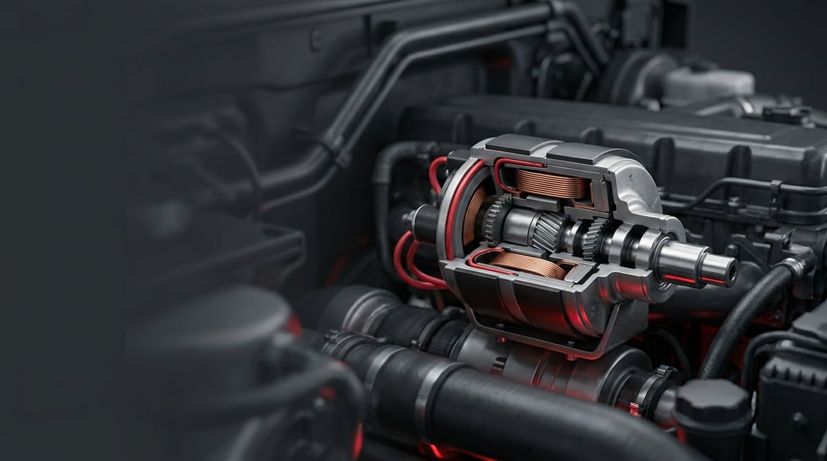
When a vehicle does nothing with the ignition on, when the engine cranks but never fires, or when a valve command is given and nothing happens at all, the part most often blamed on the workshop ramp is the pump or the valve body. Yet in the field, what usually hides behind that picture is a winding no bigger than the palm of your hand: the solenoid coil. When this small part that converts an electrical command into mechanical movement burns out, the whole system attached to it does nothing, and the vehicle is stripped down needlessly until the fault is finally traced. This guide explains, through the eyes of a workshop foreman and a service technician, what the solenoid coil does, how it fails, how it is diagnosed with measurements, and which mistakes during replacement come straight back to the vehicle.
What Is a Solenoid Coil? Function and Operating Principle
A solenoid coil is an electromagnetic winding that generates a magnetic field when current passes through it and pulls the movable core (armature) inside the valve; on a heavy commercial vehicle it opens and closes fuel shut-off and fuel system valves on electrical command. In heavy commercial applications it is typically supplied with 24 V DC, draws 8–30 W and changes position within 10–60 ms. When the coil burns out, the system cannot carry out the given command even if the valve is mechanically sound.
The same part goes by several names in the field and in catalogues: solenoid coil, magnetic coil, valve coil, electromagnet winding, and in the fuel shut-off application stop solenoid. All of them do the same job: turning the current flowing through a copper winding into magnetic force. Whatever name it is searched under, the selection criteria stay the same: supply voltage, coil body form and OE reference number.
The operating principle is simple but the tolerance is narrow. The ignition switch or control unit applies voltage to the coil, current flows through the winding and the iron core in the middle of the coil becomes magnetised. The magnetic field pulls the movable armature inside the valve against spring force; as the armature shifts, the valve passage opens or closes. When the current is cut, the magnetic field collapses and the spring pushes the armature back to its initial position. In other words, the coil does not manage the fluid directly, it only moves the valve; the part in contact with the fluid is the valve body. This distinction is vital in diagnosis, because the valve may be jammed while the coil is healthy, or exactly the opposite may apply.
Two typical control methods are seen on heavy commercial vehicles. The first is full voltage (on/off) control: the coil is either given full supply or none at all. The second is pulse width modulated (PWM) control, where the control unit switches the coil at high frequency and thus reduces the average current. Some fuel shut-off applications also use a dual winding arrangement: the thick-wire pull-in winding pulls the armature strongly for a short period, while the thin-wire hold winding maintains the position at low current. If the pull-in winding is left energised continuously, it heats up and burns within minutes; this is one of the most common coil burnout scenarios encountered in the field.
Division of work between the coil and the valve body
A solenoid coil represents the electrical side of the valve; hydraulic or pneumatic sealing is the job of the valve body. In most designs the coil slides onto the sleeve on top of the valve body and is secured with a single nut, which means the coil alone can be replaced without draining the system. From a service point of view this separation is a major advantage: in an electrical fault the valve is not removed, the fluid is not drained, only the winding is renewed.
Components and auxiliary elements
- Copper winding and bobbin (coil body): the enamelled wire that generates the magnetic field and the plastic carrier body.
- Magnetic circuit parts: core, sleeve, pole piece and outer magnetic frame.
- Armature and return spring: the movable core and the spring that pushes it back to its initial position.
- Encapsulation resin: the potting material that protects the winding against moisture, vibration and heat.
- Connector and seal: socket form, gasket/O-ring and cable entry sealing.
- Retaining nut and washer: the elements that position the coil on the sleeve.
- Suppression (freewheeling) diode or varistor: the protective element that damps the reverse voltage spike generated when the coil is switched off.
- O-ring and sealing kit: the elements supplied in the repair kit on the valve body side.
| Coil type | Typical supply | Typical power / current | Heavy commercial application example |
|---|---|---|---|
| Single winding on/off coil | 24 V DC (12 V variant available) | 8–20 W · 0.3–0.9 A | Fuel system solenoid valves, control valves |
| Dual winding (pull-in + hold) coil | 24 V DC | High short-duration current on pull-in, low current on hold | Fuel shut-off (stop) solenoid applications |
| PWM controlled proportional coil | 24 V DC, modulated | Average current set by the control unit | Proportional flow/pressure control valves |
| High protection class externally mounted coil | 24 V DC | 10–30 W | Under-chassis positions exposed to mud and salt |
| Coil/valve assembly renewed with a repair kit | Depends on the valve assembly | According to the assembly rating | Valves with fatigued sealing elements but a sound winding |
On the electrical and environmental requirements side, solenoid coils are assessed against the ISO 16750 family of environmental/electrical load conditions defined for road vehicle electrical equipment, against the IEC 60529 (IP code) definition in terms of protection class, and against ECE R10 for electromagnetic compatibility. On coils using an industrial style connector, the socket geometry often corresponds to the DIN EN 175301-803 family. These standard families are given as guidance; which class a specific part falls into must be verified from the relevant OE catalogue.
How do you recognise a solenoid coil fault?
Solenoid coil faults appear in three main forms: broken winding (open circuit), winding short circuit and leakage to the body. The most frequent picture in the field is an open-circuit winding after thermal fatigue, with the valve not moving at all. The table below matches typical symptoms with probable causes and verification methods.
| Symptom | Probable cause | Check / verification |
|---|---|---|
| Command is given but no click is heard from the valve | Broken winding (open circuit) or supply not reaching the coil | Voltage measurement at the connector; resistance measurement across the coil terminals (infinite reading means a broken winding) |
| Fuse blows or the control unit output protects itself | Short circuit inside the winding, harness contact with the body | Resistance measurement (clearly below the nominal value means a short circuit); the coil is disconnected and the circuit retried |
| Works when the vehicle is cold, fails to carry out the command once warm | Thermally fatigued winding; resistance rises when hot and pull-in force drops | Separate resistance measurements cold and hot; retest at operating temperature |
| Coil body overheats, plastic is deformed or there is a burnt smell | Coil of the wrong voltage, failure to switch to the hold winding on a dual winding system, remaining permanently energised | Comparison of the label voltage with the vehicle voltage; monitoring of the control signal with an oscilloscope or test lamp |
| Fault recurs in damp weather or after washing | Fatigued connector seal, cracked encapsulation, insulation leakage to the body | Insulation resistance measurement (coil terminal to body); drying the socket and retrying |
| Valve clicks but the system does not respond | Coil is sound, armature or valve body jammed, fluid side blocked | Magnetic field test with a screwdriver on the core with the coil removed; mechanical movement check of the valve |
| Fault is intermittent and appears when the vehicle is shaken | Loose connector pin, hairline break in the cable, slackened retaining nut | Measurement under vibration while loading the harness; check of pin tightness |
| Open circuit or short circuit fault code in the control unit | Loss of continuity or leakage in the coil circuit | Reading the code together with its freeze frame data, then verifying the coil resistance by measurement |
Quick differentiation by resistance measurement
Solenoid coil diagnosis centres on the ohm measurement. The socket is disconnected, the multimeter is set to the resistance range and connected to the two coil terminals, and the reading is compared with the label/catalogue value of the part. If the measurement is infinite the winding is broken; if it is clearly below the nominal value there is a short circuit inside the winding. Since the resistance of copper rises with temperature, take the measurement on as cold a part as possible and, in doubtful cases, compare a hot and a cold reading. The acceptance range is specific to the part; the binding value comes from the OE catalogue.
Insulation and body leakage check
A solenoid coil winding that leaks to the body produces the most intermittent and most frustrating type of fault: the vehicle works flawlessly when dry and fails to carry out the command after washing or rain. To check this, the insulation resistance between either coil terminal and the metal body is measured; on a sound coil this value must be very high (in practice in the megaohm range). A low reading points to a crack in the encapsulation or to moisture ingress, and the coil is renewed.
Magnetic field test and audible verification
The fastest field test for a solenoid coil without removing it is to bring a small steel screwdriver close to the coil body at the moment the command is given: if the winding is working, a clear magnetic pull is felt at the tip. The second method is to listen; a crisp click at the moment of command shows that the armature has moved. If there is a click but the system does not respond, the culprit is not the coil but the valve body or the fluid side. These two simple tests are the cheapest barrier against unnecessary part replacement.
Further reading
For a plain-language technical overview of this subject, see the reference article on Wikipedia. Always confirm specific figures and procedures against the vehicle manufacturer service data.
How is a solenoid coil replaced? Step by step
Solenoid coil replacement is a short job that in most designs can be carried out without draining the system; the real risk lies on the electrical side and in assembly discipline.
- Secure the vehicle: Stop the engine, apply the parking brake, chock the wheels and disconnect the battery isolator/negative terminal. Do not start work on a hot engine or a pressurised system.
- Verify the fault by measurement: Before removing the coil, measure the supply voltage at the connector and then the coil resistance. If there is no supply, the problem is not in the coil but in the circuit; replacing the coil will not solve the fault.
- Clean the area: Free the coil and the area around the valve of dust, mud and oil with compressed air and a clean cloth. Dirt that falls during removal is carried into the valve seat and the connector.
- Disconnect the connector correctly: Release the locking tab of the socket and pull it by its body; never pull on the cable. Sockets pulled by the cable develop hairline breaks that come back as intermittent faults weeks after assembly.
- Mark the fitting position: Note or photograph the cable exit direction of the coil and any orientation mark. The cable of a coil fitted at the wrong angle becomes taut and rubs against the neighbouring part.
- Undo the retaining nut: Loosen the nut holding the coil on the sleeve with a correctly sized spanner and do not lose the washer. Pull the coil off the sleeve straight along its axis without rocking it; if it is tight, work it off with a slight rotation and do not use a lever.
- Inspect the removed part: Burn marks, a swollen plastic body, a blackened connector pin or cracked encapsulation reveal the root cause of the fault. If you find a burnt coil, also investigate the possibility of excess current or permanent energising in the circuit; otherwise the new one will burn for the same reason.
- Verify the new coil: Compare the voltage rating on the label, the inner diameter, the length, the connector form and the OE reference with the old part side by side. Measuring and recording the resistance of the new coil before fitting creates a reference for future services.
- Renew the seals, seat the coil and torque it: If the valve body has also been removed, always renew the O-ring and sealing elements from the repair kit; an O-ring that is removed and reused starts to leak on the first thermal cycle. Then slide the new coil onto the sleeve without forcing it, fit its washer and tighten the retaining nut with a torque wrench to the low value specified by the manufacturer. Overtightening cracks the plastic body, while undertightening allows the coil to move on the sleeve under vibration and reduces magnetic efficiency.
- Arrange the socket and the cable: Seat the connector fully until the lock clicks, verify that its seal is in place and clip the cable along its original route without tension. The cable must not touch a hot surface or a moving part.
- Test and clear the codes: Reconnect the battery, give the command and verify the click and the expected system response. Clear the fault codes, then read them again after a short test drive or operating cycle; also check the temperature of the coil body by hand. Abnormal heating means the problem in the circuit is still present.
What are the common mistakes in solenoid coil replacement?
Most mistakes in solenoid coil replacement stem not from the part itself but from a failure to investigate the root cause of the fault.
- Replacing parts without measuring: Changing the coil when no supply voltage is present at all is a waste of time and money; voltage is measured at the socket first.
- Voltage mismatch: Fitting a 12 V coil to a 24 V system burns the winding within minutes; the label value is always verified.
- Pulling the connector by the cable: Removal without releasing the locking tab loosens the pins and creates hairline breaks.
- Striking the encapsulation surface: Forcing a stuck coil with a hammer or a lever deforms the magnetic circuit and the winding.
- Reusing seals: When the valve body is removed, the O-ring and sealing elements from the repair kit must be renewed.
- Changing the cable route: A cable not fitted into its original clips moves closer to the exhaust, chafes under vibration and breaks in time.
- Fitting the coil onto a dirty sleeve: Rust and deposits on the sleeve surface prevent the coil from seating fully and reduce magnetic efficiency.
- Ignoring the suppression diode: In a circuit where the protective element is not working, the voltage spike at switch-off wears out both the coil and the control output.
- Skipping the mechanical condition of the valve: If only the coil is changed while the armature is jammed, the fault continues unchanged.
- Handing the vehicle over without testing: A single trial on a system that has not reached operating temperature will not catch thermal faults.
Solenoid coil technical values and check points
The values given below for the solenoid coil are general reference ranges commonly encountered in heavy commercial vehicle fuel and control systems. The application, winding design and year of manufacture change these ranges; the binding data is always the OE catalogue of the part and the service manual of the vehicle.
| Parameter | Typical range (general reference) | Note |
|---|---|---|
| Nominal supply voltage | 24 V DC (12 V DC in some applications) | The label value must match the vehicle system exactly |
| Operating voltage range | Approximately 85–110 percent of nominal | At low voltage the pull-in force drops and the valve may not open fully |
| Coil resistance (20 °C) | Approximately 15–70 ohm | Varies with the power class; the acceptance range is specific to the part |
| Current draw | 0.3–1.2 A | Briefly higher on pull-in with the dual winding type |
| Power consumption | 8–30 W | Selected close to the lower band on continuously energised types |
| Response (switching) time | 10–60 ms | Spring force and fluid pressure affect the time |
| Operating temperature range | Approximately -40 °C to +120 °C | Runs close to the upper limit in an engine bay position |
| Winding insulation class | Class F or H (approximately 155–180 °C) | The higher class is preferred in continuously energised applications |
| Protection class (IEC 60529) | IP65–IP69K range | The higher class is required in under-chassis positions exposed to washing |
| Insulation resistance to body | High, in the megaohm range when sound | A low reading means moisture ingress or a crack in the encapsulation |
| Operating pressure of the driven valve | Fuel side 0.5–10 bar · pneumatic side 8–12.5 bar | Pressure is data of the valve body, not of the coil |
| Connection point | Typical torque band (general reference) | Application note |
|---|---|---|
| Coil retaining nut (on the sleeve) | 3–8 Nm | Low torque; overtightening cracks the plastic body |
| Valve body connection to the block/manifold | 15–35 Nm | With a new sealing element |
| Mounting bracket bolt | 8–12 Nm | Keeps the vibration load away from the coil |
| Screwed electrical terminal connection (if fitted) | 1–3 Nm | Overtightening deforms the pin housing |
- Is the coil resistance within the catalogue band on a cold measurement?
- Is the insulation resistance between the coil terminal and the metal body high?
- Are the connector pins bright, or is there blackening or green corrosion?
- Is the socket seal in place and flexible, and is the locking tab intact?
- Are there cracks, swelling or burn marks on the coil body?
- Is the retaining nut at the correct torque, or does the coil move on the sleeve?
- Is the cable on its original route and clipped, or does it touch a hot surface?
- Is the coil temperature at a normal level after operation?
- Is the control signal cut off within the expected time, or does it stay permanently energised?
How is solenoid coil maintenance carried out and its service life extended?
A solenoid coil has no declared replacement interval; three factors determine its service life: heat, moisture and vibration. A coil supplied with the correct voltage, kept dry and seated properly on its sleeve is one of the long-lived parts of the vehicle and can work faultlessly for hundreds of thousands of kilometres. A coil with a leaking socket, a taut cable or a permanently energised circuit, by contrast, can burn out before a single season is over. The most common cause of early failure in the field is not the part itself but a poor mounting position where heat and moisture act together.
- Connector care: On every electrical job, verify that the socket seal is in place; clean blackened pins and use a suitable contact protector.
- Washing discipline: Do not aim the high-pressure washer lance directly at the coil and the socket; even with a high IP class, a hot water jet from close range shortens seal life.
- Cable routing: Fit the cable into its original clips at every service; a cable that is taut, chafing or passing close to a hot surface fails before the coil does.
- Vibration check: A slack bracket and a loosened retaining nut let the coil move on the sleeve; this must be checked by hand at every periodic service.
- Voltage quality: A weak battery, an oxidised earth point or a fatigued alternator delivers low voltage to the coil; at low voltage the armature does not pull in fully and the coil heats up needlessly.
- Energised duration: Not leaving the vehicle on the ignition unnecessarily directly reduces the thermal load on continuously energised coils.
- Not neglecting the valve side: Dirty fluid jams the armature; a coil trying to pull a jammed armature draws more current and becomes fatigued. Filter maintenance also extends coil life.
- Spare stock logic: In fleet operations, keeping one suitable spare coil in stock per vehicle reduces roadside downtime from hours to minutes.
On the fleet side, the most efficient approach is to think of the coil not on its own but together with the valve assembly. Renewing the sealing elements with a repair kit while the valve body is already off is far more economical than the cost of bringing the vehicle back into the workshop a few months later. And the five-minute temperature and click check carried out after coil replacement is the cheapest insurance against a repeat fault.
Related categories: Solenoid Coil
Main guide: What Is a Fuel Injector? How to Recognize Injector Failure Symptoms
Tags
Frequently Asked Questions
- How do I identify a solenoid coil fault with a multimeter?
- Disconnect the socket, set the multimeter to the resistance range and measure the resistance between the two coil terminals. If the measurement is infinite the winding is broken; if it is clearly below the nominal value there is a short circuit inside the winding. Then check the insulation resistance between one coil terminal and the metal body; a low value here indicates moisture ingress. In heavy commercial applications the coil resistance is seen in a general reference band of 15–70 ohm, but the acceptance range is specific to the part and must be verified from the OE catalogue.
- Are a solenoid coil and a solenoid valve the same thing?
- They are not the same thing. A solenoid valve is the complete assembly formed by the body that directs the fluid and the coil that moves it; a solenoid coil is only the electrical part of that assembly, that is, the winding that generates the magnetic field. The practical consequence is this: in a coil fault, most designs allow only the winding to be changed without draining the system, whereas in a valve body fault the fluid side is opened up and the sealing elements are renewed.
- Why does a solenoid coil burn out?
- The most common causes are the use of a part with the wrong voltage, the coil staying energised longer than it was designed for, failure to switch to the hold winding on dual winding systems, the armature not pulling in fully because of low supply voltage, and excess current drawn while trying to move a jammed valve. Moisture ingress and a disabled protective element that damps the voltage spike at switch-off also shorten winding life.
- Can a solenoid coil be repaired or rewound?
- In heavy commercial vehicle applications, coil repair is not recommended. The winding is produced as a single unit encapsulated in resin; rewinding compromises both the insulation class and the protection class, and when the number of turns and the wire cross-section cannot be matched exactly, the pull-in force changes. A faulty coil is replaced, not repaired.
- How do I test that the valve is working while the solenoid coil is fitted?
- A crisp click from the valve at the moment the command is given shows that the armature has moved. If you cannot hear the sound, bring a small steel screwdriver close to the coil body; if the winding is working, a clear magnetic pull is felt. If there is a click and a magnetic field but the system does not respond, the culprit is not the coil but the valve body or a blockage on the fluid side.
- Can a 12 V solenoid coil be used on a 24 V system?
- It cannot. A winding supplied with twice its nominal voltage draws current far above its design value and usually burns out within minutes. In coil selection, the voltage rating on the label must match the vehicle system exactly; two coils that look alike having different voltages is a situation frequently met in the field.
- How long does solenoid coil replacement take?
- What determines the time is not the coil itself but access. In an easily reached position, with the valve left in place, coil replacement including measurement and testing is completed in most applications in half an hour to one hour. If the cab has to be tilted, a cover removed or the whole valve assembly taken down, the job can extend to several hours. Clearing the fault codes and the second check after an operating cycle must be added to this; the exact time is set by the labour item in the service manual.
- Does a solenoid coil fault leave the vehicle stranded?
- It depends on the application. When a coil serving as a fuel shut-off (stop) solenoid fails, the engine either does not run at all or stops unexpectedly; this is a fault that strands the vehicle directly. The failure of a coil driving an auxiliary control valve, on the other hand, is usually limited to the loss of the related function. In both cases the journey should not be continued without reading the fault code.
- Why did the solenoid coil I have just fitted burn out again so soon?
- This picture almost always shows that the root cause has not been eliminated. If permanent energising in the circuit, a wrong control signal, low or high supply voltage, a jammed armature or moisture ingress is still present, the new coil will burn out the same way. Before fitting a new part, the supply voltage, the duration of the control signal and the mechanical movement of the valve must always be verified.
- How do I select the correct solenoid coil?
- The vehicle model alone is not enough for selection. The nominal voltage, the inner diameter and length of the coil, the connector form, the cable exit direction and, where possible, the OE reference number on the old part must be used together. Searching the VADEN catalogue can be done using this data: you can search the OE reference number directly to reach the matching VADEN part number, or select the coil suitable for your vehicle from the application list. Measuring the old coil with a caliper and comparing the label voltage is the safest final step for dimensional verification.
Related Articles

Fuel Water Separator Filter: Symptoms, Replacement & Care
Truck fuel water separator filter and housing: how it works, water sensor, drain valve, heater, fault symptoms, replacement, bleeding and maintenance.
Diesel Injection Line & Fuel Pipe: Faults, Repair, Maintenance
Heavy truck injection line and fuel pipe guide: high-pressure vs supply line, leak and air ingress diagnosis, torque sequence, replacement and maintenance.

Feed Pump & Hand Primer: Faults, Replacement, Maintenance
Truck feed pump and hand primer guide: how they work, fault symptoms, low pressure diagnosis, replacement steps, torque values, bleeding and maintenance tips.


