ALB Load Sensing Valve: Faults, Replacement & Setting Guide
Rear axles locking when the truck runs empty, or longer stopping distances when loaded, point to the ALB load-sensing valve: diagnosis and setting.
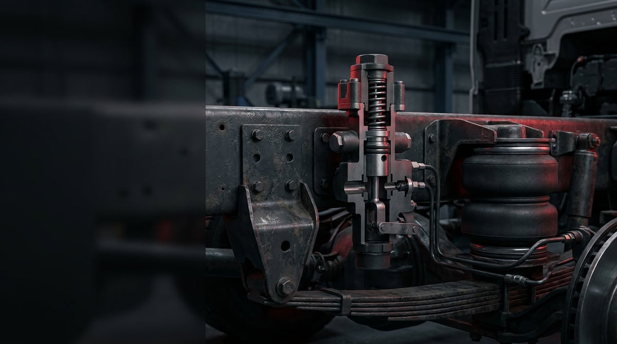
If your rear wheels lock up when you brake with an empty trailer, if stopping distance stretches out when the vehicle is loaded, or if the ABS lamp only lights under certain load conditions, one of the first parts that should come to mind is the ALB load sensing valve. Known in the field as the "ALB", "load valve" or "load-dependent valve" — and in German-language sources as the ALB-Regler (Automatischer lastabhängiger Bremskraftregler — automatic load-dependent brake force regulator) — this part scales the brake pressure sent to the rear axle according to the vehicle's current load. It is a small housing, but when it is set incorrectly or worn out inside, the consequence shows up directly in stopping distance and in the inspection report. In this guide we explain, in workshop language, what the ALB valve does, how it fails, how it is replaced, and which checkpoints need to be inspected.
About this document: Prepared by the VADEN technical team, drawing on manufacturing and field-service experience with heavy commercial vehicle brake systems. The values given here are typical reference ranges; the exact setting pressure, lever angle, torque and tolerances for each vehicle/trailer are the values written in the vehicle manufacturer's current service manual and on the ALB label/plate on the vehicle. In practice, those values prevail. Last updated: September 2026.
Heavy commercial vehicle air brake systems are designed within the framework of ECE R13 (UN/EU braking regulation) and ISO 611.What Is the ALB Load Sensing Valve? Function and Operating Principle
The ALB load sensing valve is a mechanical-pneumatic brake force regulating valve that automatically reduces (scales) the air pressure sent to the rear axle brake chambers on heavy commercial vehicles and trailers, according to the instantaneous load on the axle.
Its logic rests on a simple physical fact: braking force cannot exceed the load the tyre presses onto the road. While an empty tractor unit may carry a few tonnes on its rear axle, when loaded the same axle can carry three to four times that. If the pressure coming from the brake valve is delivered the same in both cases, the rear wheels lock when empty (the vehicle skids, the tyre flat-spots, the ABS constantly intervenes), while when loaded the braking is inadequate. The ALB valve steps in: by reading the amount the suspension is deflected, it generates the information "how loaded is this vehicle right now" and converts the input pressure into an output pressure proportional to it.
Measurement is done by one of two methods. On vehicles with mechanical suspension (leaf spring), the valve is mounted to the chassis, and the lever at its end is connected to the axle or axle clamp via a link rod and an elastic element (rubber cord/torsion element). As the vehicle is loaded, the chassis moves closer to the axle, the lever angle changes, and the cam/curve profile inside the valve shifts the ratio. On air-suspension vehicles the job is easier: bellows pressure is already directly proportional to load, so the valve takes a control line directly from the air suspension bellows — this type is generally called an air ALB or bellows-controlled load valve.
What happens inside?
In the valve body there is a balance piston between the inlet (control pressure coming from the brake valve) and the outlet (going to the rear chambers/relay valve). The lever position shifts the effective area ratio of this piston or the cam curve. In the empty position the outlet/inlet ratio drops significantly (a reduction typically in the range of 1:2 to 1:5 depending on the vehicle), while in the fully loaded position the ratio approaches 1:1 — that is, the valve becomes almost transparent, passing all of the inlet pressure through. For every load condition in between, the valve produces an intermediate ratio corresponding to the lever angle. Most designs also have an emergency safety feature: if the link lever breaks or the rod drops, the valve settles into the "fully loaded" position, meaning it passes full pressure rather than cutting braking force. This is a deliberate choice; it is preferable to lock up a little early when empty than to be left without brakes.
Its place in the system and neighbouring parts
The ALB valve does not work alone. In a typical rear axle circuit the sequence is: foot brake valve - ALB load sensing valve - relay valve (or directly the ABS modulator) - brake chambers. On trailers, the trailer brake valve (emergency/relay) and, where fitted, the EBS modulator also join this chain. That is why it is wrong to immediately blame the ALB for a "rear brake not holding" complaint; the relay valve, modulator, chamber and lines can all produce the same result.
- Valve body: usually cast aluminium; numbered over the inlet (1), outlet (2) and exhaust (3) ports.
- Control lever: the lever that carries the load information to the valve; it may have an adjustment scale or a scale hole on it.
- Link rod and elastic element: transmits axle movement to the lever while cushioning it; damps road shocks.
- Balance piston / cam profile: the internal mechanism that carries out the ratio change.
- Diaphragm and seal kit: the parts most exposed to wear and ageing; they provide the seal.
- Exhaust and dust cap: keeps the discharge path open and clean; if it clogs, the brake releases late.
- Adjustment plate / label: where the empty and loaded pressure values and the lever angle are written — the source of information most often overlooked in the field.
Type comparison: which ALB on which vehicle?
| Application / suspension type | ALB type | Load signal from where | Typical application |
|---|---|---|---|
| Leaf-sprung truck rear axle | Mechanical lever ALB | Lever + rod + elastic element (axle–chassis distance) | Classic tractor/truck rear axle, construction-type vehicles |
| Air-suspension tractor / trailer | Air (bellows-controlled) ALB | Control line from the air suspension bellows | On-road tractor, curtainside/reefer trailer |
| Trailer (mechanically sprung) | Trailer-type mechanical ALB | Axle link rod | Tipper, lowbed, flatbed trailer |
| Drawbar trailer / tandem axle | Lever ALB + relay valve combination | Lever, often from a shared axle bridge | Agricultural/forestry trailer, tandem carrier |
| Manually adjusted application | Manual load valve (empty/half/full stepped) | Driver/operator lever | Older-generation trailers and some construction machine tractors |
| Modern vehicle with EBS | Electronic load sensing (ALB function within EBS) | Pressure sensor + EBS ECU software | Modern EBS tractor/trailer — a separate mechanical ALB may not be present |
On the brake pneumatics side, Knorr-Bremse, WABCO/ZF and Bendix type system architectures are widespread in the field; while OE names on the engine/cooling side such as Bosch, Mahle, Behr or Voith are only indirectly related to the ALB circuit (compressor flow, air quality). In VADEN products these names are referenced only in the context of equivalent/type compatibility.
Part number verification is essential. ALB valves look almost identical from the outside, but their internal ratios, port threads and lever geometries differ. When a valve with the wrong ratio is fitted, the vehicle runs, does not leak air, and no lamp lights — but the brake balance is wrong, and you will only realise it on a brake test bench or during an emergency stop. Before ordering, always cross-check: (1) the vehicle chassis/VIN number, (2) the OE number on the old valve, (3) the empty/loaded pressure values written on the ALB label on the vehicle, and (4) the suspension type. If in doubt, send a photo of the old part's label to the VADEN technical support line.
Fault Symptoms and Diagnosis
ALB faults most often arrive not with a clear complaint like "the brake isn't holding", but with behaviour that changes according to the load condition. The distinguishing question is this: does the problem occur when empty, when loaded, or in both? The answer points you straight to the valve or elsewhere.
| Symptom | Possible cause | Check / verification |
|---|---|---|
| Rear wheels lock up early on an empty vehicle, ABS activates frequently | Valve stuck permanently in the "loaded" position; lever/rod broken, seized or wrongly set | Check by hand whether the lever moves freely; with the vehicle empty, measure the pressure at the outlet port with a gauge and compare it with the empty value on the label |
| Weak rear brake on a loaded vehicle, long stopping distance | Valve stuck permanently in the "empty" position; internal mechanism worn, lever angle wrong | With the vehicle loaded, measure inlet and outlet pressure simultaneously; the ratio is expected to approach 1:1 |
| Brake imbalance: vehicle pulls to one side under braking | One-sided throttling, line restriction, one valve deviating in a dual-ALB application, chamber/lining difference | Measure force per axle on a brake test bench (roller tester); report the left/right difference |
| Continuous air leak from the valve body or lever shaft | Diaphragm torn, O-ring/seal aged, housing crack | Soapy water test: separately with the brake applied and released; a continuous leak from the exhaust port points to an internal sealing problem |
| When the brake is released, the rear chambers exhaust slowly, the brake "drags" | Exhaust port blocked, dust cap lost, internal piston not returning, even ice/moisture | Visually inspect the exhaust port and dust cap; check the air dryer and tank drain; if there is water in the system, suspect freezing |
| Rejection of brake distribution or rear axle force at inspection (periodic/roadworthiness) | ALB setting has drifted, wrong-ratio valve fitted, lever geometry disturbed | Take the measured values from the report; compare with the ALB label on the vehicle and carry out an adjustment check |
| On an air-suspension vehicle, brake behaviour does not change at all when the load changes | Control line from the bellows broken/crushed, line end blocked | Disconnect the control line; verify with a gauge that the suspension bellows pressure reaches the valve |
| Rattle/play noise at the lever connection, rod swinging | Elastic element fatigued, joint/ball joint has play, rod bent | With the vehicle on the ground, move the lever up and down by hand; noticeable play is unacceptable |
Step-by-step diagnostic logic
First verify the system pressure: are the tanks full, does the compressor reach cut-out pressure, is the dryer doing its job? Any ALB measurement made with low system pressure is misleading. Then measure the inlet pressure — before blaming the ALB, confirm that the correct pressure is reaching it. Only after that should you look at the inlet/outlet ratio. Most of those who skip this order end up replacing a sound valve.
Dual measurement with gauges: the most reliable method
Connect two gauges to the ALB inlet and outlet at the same time (from the test points if available, otherwise with a T-fitting). Test the vehicle first empty, then if possible loaded. By applying the foot brake progressively, bring the inlet pressure to the test value on the label (typically a reference point around 5–6 bar) and read the outlet. When empty, the outlet should be significantly lower; when loaded, very close to the inlet. If there is no difference at all between the two conditions, or the difference is in the reverse direction, the valve is either faulty or out of adjustment.
What to rule out before blaming the valve
Worn linings, a seized caliper/cam shaft, an unadjusted brake lever (the automatic slack adjuster on S-cam systems), a fatigued chamber diaphragm, a crushed air hose and a faulty relay valve — all of these mimic an ALB fault. Especially on EBS vehicles, read the fault memory first; the system will often tell you the pressure sensor data directly, and you need not touch the mechanical ALB at all.
Standards and further reading
This subject is governed by the equipment rules for air-braked commercial vehicles. In the United States the federal air brake standard, FMVSS 121 (49 CFR 571.121) defines the reservoirs, protection and timing a compliant system must provide, and Europe applies the equivalent limits of UNECE Regulation No. 13. For further detail, see the illustrated reference guide at airbrakecompressor.com. Always confirm specific figures against the current regulation and the vehicle manufacturer service data.
Outside the United States the equivalent duties sit in national law. In the United Kingdom, regulation 18 of the Road Vehicles (Construction and Use) Regulations 1986 requires every part of the braking system to be maintained in good working order. In Canada, air brake systems fall under the Motor Vehicle Safety Regulations, which contain CMVSS 121.
Replacement / Installation Steps
Safety and PPE — do not skip. Working on a compressed air system carries a serious injury risk. The vehicle must be on level ground, the engine stopped, ignition off, chocks in place, and the parking brake mechanically secured. Do not disconnect any line before the spring brake (chamber) energy has been released and the system has been vented. Compressed air remaining in the circuit will whip the hose like a lash when the fitting is opened. If lifting is required, an axle stand/jack safety measure is essential — do not trust the jack alone. PPE: safety glasses, work gloves, steel-toe boots, and ear protection if needed. On an air-suspension vehicle the chassis can drop suddenly as the suspension bellows deflate — keep hands/feet clear of the gap between axle and chassis.
- Preparation and verification: Take the vehicle and trailer details (VIN, axle type, suspension type); compare the new valve's OE/equivalent number and lever type with the old part. Photograph the ALB label on the vehicle — it may be lost or become illegible after removal.
- Record the current setting: Before removal, measure and note/photograph the lever's current angle, the rod length and, if present, the position on the adjustment scale. This is the most valuable reference for the initial setting after installation. Rough alignment is not enough; record it in millimetres and degrees.
- Secure and vent the system: Place the chocks, switch off the ignition, and vent the air tanks per the manufacturer's procedure. If necessary, mechanically release the spring brake chambers (release bolt). Confirm from the gauge that the system has genuinely been reset to zero — do not say "it's probably vented".
- Mark and disconnect the lines: Label the inlet (1), outlet (2), exhaust (3) and, if present, the suspension control line before disconnecting. A swapped inlet/outlet line makes the valve work in reverse and preserves the fault complaint exactly. Cap the disconnected line ends; keep dust and moisture out of the system.
- Disconnect the lever linkage and the valve: Separate the link rod/elastic element from the end of the lever, then remove the valve's mounting bolts on the chassis. If the rod and joints are bent, cracked or have play, renew them together with the valve — a fatigued rod will not hold the new valve's setting.
- Clean the mounting surface and the lines: Clean rust and dirt off the bracket surface and check the bolt threads. Clean the line ends and fittings with compressed air; if there is accumulated moisture/oil inside, also address the dryer and tank drain. Dirty air is the new valve's fastest enemy.
- Fit the new valve: Position the valve in the correct orientation (port directions and lever direction per the manufacturer's drawing), start the bolts by hand and position the body, then tighten progressively to the torque specified by the manufacturer. Do not force the body; the aluminium body cracks under excessive torque.
- Connect the lines: Connect the inlet, outlet, exhaust and, if present, the control line according to your labels. On threaded fittings, use the appropriate sealing material per the manufacturer's instructions; never close off the exhaust port and dust cap or plug them with sealing paste.
- Set the lever: With the vehicle empty and at normal ride height (bellows at nominal pressure on air suspension), adjust according to the reference you recorded and the lever angle/rod length specified by the manufacturer. Set it by measuring, not by eye. This step is the most critical in the guide: a correct valve is as dangerous with the wrong setting as a faulty valve.
- Pressurise and carry out a leak test: Fill the system up to cut-out pressure. Using soapy water, test all fittings, the body parting surface and the lever shaft separately with the brake applied and released. Do not leave a spot where you see bubbles thinking "it'll seat in".
- Pressure verification and road test: Measure the inlet/outlet pressure with a gauge when empty and compare with the value on the label; repeat when loaded if possible. Then carry out a low-speed brake test in a safe area, checking for lock-up/pulling. If possible, report and record the axle forces on a roller brake test bench.
Points to Watch (Common Mistakes)
The most common and most costly mistake: setting the lever "by eye". The relationship between the ALB valve's lever angle and the outlet pressure is not linear; a deviation of a few degrees can significantly shift the rear axle pressure on an empty vehicle. The "the old one was here, I put it in the same place" approach copies the fault, because the old valve was already out of adjustment. Always set the adjustment to the value on the vehicle label/service manual, and by measuring.
Mixing up the inlet–outlet line. The ports are numbered (usually 1 inlet, 2 outlet, 3 exhaust), but two similar unlabelled lines are easily swapped during removal. A reverse-connected ALB does not leak air and looks normal to the eye; however, the load sensing function does not work. If the complaint continues exactly the same after replacement, this is the first place to look.
- Using a fatigued rod/elastic element with a new valve: A joint with play causes the setting to drift on the road. When replacing the valve, also inspect the linkage kit.
- Blocking the exhaust port: Discarding the dust cap, smearing it with paste, or not cleaning off mud/rust buildup lengthens the brake release time. This means a dragging lining and an overheating drum.
- Over-torquing: On aluminium bodies and brass fittings, the "let me tighten it hard so it doesn't leak" mentality produces cracks and stripped threads. The torque value is the manufacturer's, not the feel of your arm.
- Continuing to work with a dirty/wet air system: If the air dryer cartridge has reached the end of its life, the new valve will give the same fault before long. Replacing parts without solving the root cause is an expensive cycle.
- Adjusting on a loaded vehicle: Unless stated otherwise, the ALB is adjusted with the vehicle empty and at nominal ride height. A setting made under load leaves a dangerous lock-up profile when empty.
- Skipping the brake test after replacement: Unacceptable in terms of documentation and safety. An ALB job declared "done" without measurement is an unfinished job.
- Looking for a mechanical ALB on an EBS vehicle: On modern EBS systems the load sensing function is carried out electronically; instead of removing a mechanical valve there, you need to read the fault memory and the pressure sensor.
- Ignoring a suspension fault: A broken leaf, a deflated bellows or an unadjusted levelling valve feeds the ALB wrong load information from the start. The valve works correctly, but the result is wrong.
Technical Values and Checkpoints
The table below contains values that are typical / general reference in heavy commercial vehicle brake circuits. None of them is a setting target for a specific vehicle; the vehicle manufacturer's service manual and the ALB label on the vehicle prevail.
| Parameter | Typical reference range | Note |
|---|---|---|
| System working pressure (cut-out pressure) | approx. 8–12.5 bar (≈115–180 psi) | Varies with vehicle architecture; verify the system is at cut-out pressure before measuring |
| ALB test/reference inlet pressure | a check point around approx. 5–6 bar (≈70–90 psi) | The exact test point is stated on the vehicle label |
| Empty-position outlet/inlet ratio | throttling in the range of approx. 1:2 – 1:5 | Depends on vehicle and axle load; the empty value on the label prevails |
| Fully loaded outlet/inlet ratio | ≈1:1 (outlet very close to inlet) | At full load the valve is expected to behave "transparently" |
| Measurement tolerance (typical acceptance band) | approx. ±0.2–0.3 bar around the label value | The tolerance is manufacturer-specific; use the band in the manual |
| Lever travel angle (empty - fully loaded) | typically a band from a few degrees to ~25–30° | Depends entirely on the valve type and mounting geometry |
| Operating temperature range | approx. −40 °C … +80 °C | At low temperature, moisture in the system can freeze and lock the valve |
| Static leak acceptance | no visible/audible continuous leak is accepted (no bubbles in the soap test) | A system-wide pressure drop test is additionally carried out per the manual |
| Air quality (moisture/oil) | dryer working, no water coming from the tank drain | Water in the system is the most common hidden cause of ALB faults |
The same rule applies for tightening torques: the figures below are order-of-magnitude indicators, the exact value is the manufacturer's.
| Connection | Typical torque order | Warning |
|---|---|---|
| Valve body – chassis/bracket bolts | approx. 20–45 Nm | Tighten progressively and crosswise; do not load the body with force |
| Air line fittings (small diameter) | approx. 10–25 Nm | Excessive torque strips brass/aluminium threads |
| Lever locking/clamp bolt | approx. 8–20 Nm | Tighten without disturbing the setting; re-measure the angle after tightening |
| Link rod joint nut | approx. 15–35 Nm | If a self-locking nut was used, replace it with a new one |
Field tip: When measuring, connect two gauges to the inlet and outlet simultaneously. Measuring in turn with a single gauge gives a misleading result, because you cannot hold the pedal pressure exactly the same across two attempts. Also record the measurements in writing as empty and loaded — at the next service, those two lines will save you hours of fault-finding.
Quick field checklist:
- Does the lever move freely by hand and return to its spring rest?
- Is the link rod straight, is there play in the joint, is the elastic element cracked?
- Is the exhaust port open, is the dust cap in place?
- Is the ALB label legible, do the values on it match the measurement?
- Are there leaks on the body and fittings (separately with the brake applied and released)?
- On air suspension, is the control line intact and uncrushed?
- Is the suspension (leaf/bellows/levelling valve) healthy — is the correct information reaching the ALB?
- Is water coming from the tank drain, has the dryer cartridge reached the end of its life?
Maintenance and Service Life
The ALB load sensing valve is not a consumable part that is "replaced" periodically; with the right air quality and sound connection geometry it can work for many years. Three things determine its life: moisture and oil in the system, the health of the mechanical linkage, and the accuracy of the setting. On a vehicle with a neglected dryer, the diaphragm and O-rings inside the valve age far faster than expected; in winter that same moisture can freeze and lock the valve entirely. On tippers, lowbeds and construction-type vehicles the real enemy is vibration and mud — the link rod and joints fatigue long before the valve body.
- At every periodic service: check the lever and rod by hand, look for play and bending; clean the exhaust port and dust cap.
- Air quality: replace the air dryer cartridge at the interval prescribed by the manufacturer; schedule the tank drain. This alone significantly extends the ALB's life.
- Leak check: at least once a year, carry out a leak test with soapy water on the body, fittings and lever shaft.
- Setting verification: if suspension work has been done (leaf, bellows, axle, levelling valve) or the vehicle has taken a shock from the ground, always re-verify the ALB setting.
- Winter preparation: on vehicles operating in cold regions, carry out a pre-season moisture check; a frozen valve behaves like a faulty valve but may not require a part replacement.
- Brake test record: take a measurement on a roller test bench before inspection; catch ALB-related imbalances before going to inspection.
- Together with lining/drum work: when a brake overhaul is done, add the ALB circuit to the checklist too — a new lining will not compensate for an unadjusted ALB.
- Kit logic at replacement: while renewing the valve, also inspect the link rod, elastic element and seal kit; a half-done job means removing it a second time.
In short: the ALB valve is not a part that demands maintenance, but one whose conditions need attention. Keep the air dry, keep the linkage sound, set it by measuring — when all three are met, this valve will not trouble you for years. When one of the three is neglected, the bill is paid not by the valve, but by the rear tyres and the stopping distance.
The VADEN ORIGINAL ALB load sensing valve product family is manufactured with OE-equivalent ratios and geometries to cover mechanical lever and air (bellows-controlled) applications in heavy commercial vehicle and trailer brake circuits; the products go through the manufacturing and testing processes at VADEN's own facilities. When selecting the ALB valve suitable for your vehicle, cross-check with the chassis/VIN number, suspension type and the old part's OE number; for applications you are unsure about, contact the VADEN technical team together with a photo of the ALB label. When the right part is combined with the right setting, the ALB valve quietly does its job for years — and brake balance working well is exactly what that quiet means.
Related categories: ALB Load Sensing Valve · Complete · Repair Kit
Related technical guides: ABS Wheel Speed Sensor & ECU: Faults, Replacement & Care · Brake Caliper Overhaul Kit: Guide Pins, Boots & Adjuster · Air Processing Unit (APU/EAC): Faults, Replacement & Care · Pressure Limiting Valve: Faults, Replacement & Maintenance · Four-Circuit Protection Valve: Faults, Diagnosis & Replacement
Application and compatibility: Vehicle compatibility catalogue · Engine compatibility catalogue
Main guide: Truck Air Brake Valves Explained: Types, Functions and Failure Symptoms
Tags
Frequently Asked Questions
- What does the ALB valve do, in short?
- It automatically scales the brake pressure sent to the rear axle according to the vehicle's current load. When empty it throttles the pressure to prevent wheel lock-up; when loaded it passes full pressure to ensure adequate braking. In other words, it keeps braking force at a level that can be transferred to the road in every load condition.
- Are the ALB-Regler and the ALB load valve the same thing?
- Yes. The ALB-Regler (Automatischer lastabhängiger Bremskraftregler) referred to in German-language sources and in many European-origin vehicle documents is the same part known as the load sensing valve, load valve, or in the field simply as "ALB". They are different names describing the same function.
- If the ALB valve fails, will the vehicle be stranded on the road?
- Generally no — the vehicle moves and brakes, the problem is in the brake balance. In most designs, if the lever breaks the valve settles into the fully loaded position, meaning braking force is not cut off. However, this is not a safe condition: early lock-up on an empty vehicle and inadequate braking when loaded carry a serious risk of accident and inspection rejection. It must be remedied as soon as the fault is detected.
- Can I set the ALB adjustment myself?
- Because the relationship between the lever angle and the outlet pressure is not linear, the setting cannot be done reliably without gauge measurement and manufacturer values. If you have the equipment (two gauges, the vehicle label/service manual) and know the procedure, it can be done; otherwise, leave it to an authorised brake service. Setting by eye is the most common mistake we encounter.
- How often is the ALB valve replaced?
- There is no fixed replacement period; it is not a consumable. In a system with good air quality and a sound connection it works trouble-free for many years. What triggers replacement is not the calendar but the symptom: leakage, seizing, failure to hold the setting, or deviation from the label value in measurement.
- Is there a separate ALB valve on an EBS vehicle?
- On modern EBS-equipped tractors and trailers, the load sensing function is carried out electronically, via a pressure sensor and ECU software; a separate mechanical ALB valve may not be present. On such a vehicle, read the fault memory first in the event of a brake balance complaint. Mixed (EBS + mechanical backup) architectures also exist; the vehicle documentation is decisive.
- How do I tell if I've fitted the wrong ALB valve?
- You cannot tell from the outside — a wrong-ratio valve fits, does not leak, does not light a lamp. The only reliable way is measurement: read the inlet/outlet pressure when empty and loaded and compare with the values on the vehicle label. If there is a deviation, either the valve is wrong or the setting is wrong. That is why verifying at the ordering stage with VIN + old OE number + label values is far cheaper than testing afterwards.
- Why does the ALB work differently on an air-suspension vehicle?
- Because the load information is taken directly from the suspension bellows pressure instead of from a lever — bellows pressure is already proportional to axle load. These valves have no mechanical lever and rod; in their place is a control line. That is the difference in fault-finding too: you look not at play in the lever, but at the integrity of the control line and whether the bellows pressure reaches the valve.
- What should I rule out before blaming the ALB for a rear brake imbalance?
- Start with system pressure: are the tanks full, does the compressor reach cut-out, is the dryer doing its job? Then confirm the correct pressure actually reaches the valve inlet, and only after that compare inlet with outlet. Worn linings, a seized caliper or cam shaft, an unadjusted slack adjuster, a fatigued chamber diaphragm, a crushed hose and a faulty relay valve all mimic the same complaint. On EBS vehicles read the fault memory first.
- I replaced the valve but the complaint is exactly the same. Where do I look first?
- At the inlet and outlet lines. The ports are numbered (usually 1 inlet, 2 outlet, 3 exhaust), but two similar unlabelled lines are easily swapped during removal; a reverse-connected valve does not leak air and looks normal, yet the load sensing function simply does not work. The second place is the lever setting: adjusting by eye copies the old valve's error, and a link rod with play lets the setting drift on the road.
Related Articles
Trailer Control Valve: Faults, Replacement & Maintenance Guide
How the trailer control valve (Anhangersteuerventil) works on heavy trucks, its failure symptoms, gauge diagnosis, replacement steps and OE maintenance tips.

ABS Brake System: How It Works, Warning Light and Faults
Learn how the ABS brake system works on heavy trucks, why the warning light comes on, how to diagnose sensor faults, and the correct replacement steps.
Brake Chamber, Diaphragm & Hose: Faults, Replacement, Care
Learn how to spot a leaking brake chamber, measure push rod stroke, cage the power spring safely and replace the unit and hose without risk on heavy trucks.


