Four-Circuit Protection Valve: Faults, Diagnosis & Replacement
A truck losing air with no leak in sight often has a four-circuit protection valve isolating a burst line: how it prioritises brakes, diagnosis, replacement.
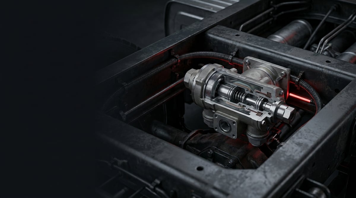
One of the most common sentences heard in the field is this: "The vehicle is losing air, but we can't find where it's escaping from." More often than not, the trail leads to a part that sits quietly between the air dryer and the brake chambers, one that hardly anyone bothers to look at: the four-circuit protection valve. On fleets running the Germany and Central Europe corridor, this part is known as the Vierkreisschutzventil, and it shows up frequently in fault records; in some markets it is also called the "distributor valve," "four-circuit valve," or simply "protection valve." Whatever the name, its job is the same: to split the pressurized air coming from the compressor into four separate circuits, and to keep the others alive when one of them bursts. This guide is written for workshops and fleet technicians who want to understand the part, diagnose its faults correctly, remove and refit it properly, and extend its service life.
E-E-A-T note: This document was prepared by the VADEN technical team, drawing on real service records encountered in the field on heavy commercial vehicle air brake systems and on OE manufacturer documentation. The values given here are typical reference ranges; for the exact opening pressure, sealing limit, and torque values specific to your vehicle, always rely on the vehicle manufacturer's current service manual. Last updated: September 2026.
What Is a Four-Circuit Protection / Distributor Valve? Its Function and Operating Principle
The four-circuit protection valve is a safety valve that distributes the pressurized air arriving from the air dryer to the front brake, rear brake, park/trailer, and auxiliary equipment circuits according to a priority order; when a leak develops in any circuit, it isolates that circuit to preserve the pressure of the others, preventing the vehicle from being left without brakes.
Its operating principle rests on a simple idea: at the outlet of each circuit there is a spring-loaded closing element that does not open until a certain pressure value is reached. When the compressor engages and begins to fill the system, the valve first charges the brake circuits (circuits 1 and 2). Until these circuits reach a safe level, air flow to circuits 3 and 4 (park/trailer and auxiliary equipment) is restricted. This way, when the engine first starts, the vehicle gets its brakes ready before filling the suspension bellows or the cab-tilt pump. This sequencing is no coincidence; it is the hardware embodiment of the "priority of the brake circuits" principle prescribed by ECE R13 and equivalent regulations.
The second and more critical function appears at the moment of failure. Suppose a cab suspension hose in circuit 4 bursts. Without a protection valve, all the air in the system would empty out through that hole and the vehicle would lose brake pressure within a few seconds. When the pressure of that circuit drops below the defined closing threshold, the protection valve shuts off the corresponding path and holds the remaining circuits at a certain level of pressure. The vehicle is therefore not left without brakes, and the driver can bring it to a safe stop.
- Body (aluminum casting or composite): Houses the inlet (1) and the four outlet ports (21, 22, 23, 24); the port numbering follows ISO 6786.
- Diaphragm / piston assembly: Separate for each circuit; the moving element that opens and closes according to the pressure differential.
- Pressure springs: Calibrated springs that determine the opening and closing pressure; factory-set and not to be adjusted in the field.
- Non-return valves (check valves): Prevent air from flowing back from healthy circuits into a faulty one.
- O-rings and sealing elements: EPDM or NBR; EPDM is generally preferred in air brake systems.
- Adjustment screws / caps: Present on some types; if the plastic safety cap has been removed, the valve has been tampered with.
- Test points (optional): Some bodies have an M16×1.5 gauge connection for each circuit.
The Difference Between Sequential (Staged) and Non-Sequential Types
The four-circuit protection valves on the market work with roughly two logics. In the sequential (staged) type, the circuits fill in a defined priority order: first the brake circuits, then the park and auxiliary circuits. This type ensures that the brakes become ready quickly at first start-up, but the filling of the auxiliary circuits is slightly delayed. In the simultaneous (parallel) type, all circuits begin to fill at the same time, and each circuit that reaches its opening pressure opens its own path. Modern European tractor units predominantly use staged-simultaneous hybrid arrangements.
This distinction matters, because when a simultaneous valve is fitted in place of a sequential one, the vehicle works normally at first glance; the problem only surfaces when a circuit bursts or on a cold morning's first start. For this reason, parts must not be selected on the logic of "the size fits, the ports match."
Circuit Numbering and Which Circuit Goes Where?
On a standard European tractor unit, the port allocation is usually as follows: outlet 21 is the front brake circuit, outlet 22 is the rear brake circuit, outlet 23 is the park brake and trailer supply, and outlet 24 is for auxiliary equipment (suspension, cab tilt, clutch boost, exhaust brake, PTO). However, this allocation can vary from manufacturer to manufacturer and by chassis type. On vehicles with truck-mounted bodywork, it is common for circuit 24 to feed a crane or tipper hydraulic system.
Its Relationship with the Air Dryer
On most vehicles, the four-circuit protection valve is located immediately after the air dryer. In some modern applications, the dryer and the protection valve are combined into a single module (APU / air processing unit). In this case, it may not be possible to replace the valve on its own; you need to look at the module's service kit or a complete replacement. On vehicles with an electronic air processing unit (EAPU type), circuit pressures are monitored by the ECU and the fault drops directly as a brake system fault code.
| Vehicle / System Family | Common Valve Type | Typical Location | Field Note |
|---|---|---|---|
| Mercedes-Benz Actros / Axor (EURO 5–6) | Staged, 4 outlets; APU-integrated on later models | Chassis left side, dryer outlet | Electronic monitoring on EURO 6; fault drops straight to the cockpit |
| MAN TGA / TGS / TGX | Staged, separate body or within a module | In close proximity to the dryer | Moisture buildup can carry over to the valve; check together with the dryer cartridge |
| Scania R / G series | Staged-simultaneous hybrid | Under the chassis, inside a protective plate | High snow/salt exposure; body corrosion is common |
| Volvo FH / FM, Renault T | Staged; APU-integrated on some models | Air processing unit block | The valve may not be available on its own; look at the module kit |
| DAF XF / CF | Staged, 4-outlet separate body | Chassis right side | Variants with different port orientations exist; physical verification is essential |
| Bus / city bus applications | 4 or 5 outlets; with door and suspension circuits | Engine bay or luggage-compartment side | The door circuit is protected separately; the circuit map is vehicle-specific |
| Knorr-Bremse-type / Wabco-type equivalent bodies | Standard ISO port layout | Variable | Bodies that look identical can have different opening pressures |
Part number verification — not to be skipped: In four-circuit protection valves, the spring calibration and opening pressure inside bodies that look almost identical from the outside can differ. When a valve with the wrong calibration is fitted, the vehicle charges up and the driver notices nothing — but when a circuit bursts, the protection does not work. For this reason, selection must always be verified with the trio of the OE number on the old part, the vehicle chassis/VIN number, and the outlet port layout. Being "the same size and the same connection" is not enough. If you are unsure, request a cross-reference check from the VADEN technical support line.
Fault Symptoms and Diagnosis
Protection valve faults are most often filed under the heading of "air leak," and the blame is usually pinned first on the brake chambers, then on the hoses. Yet the valve has its own recognizable symptoms. The table below summarizes the scenarios most frequently encountered in the field.
| Symptom | Possible Cause | Check / Verification |
|---|---|---|
| While the vehicle is parked, pressure drops across all circuits overnight | Internal sealing of the valve has failed; cross-circuit back-leak or leak to the outside of the body | Leave the reservoirs full, stop the engine, and read the gauges after 8–12 hours. If all circuits drop equally, the valve is a strong suspect. Go over the body and around the ports with soapy water. |
| Compressor runs continuously and does not cut out | Continuous leak from the valve; the air dryer purge valve may also be faulty at the same time | Isolate (blank off) the section between the dryer outlet and the valve inlet to determine which side the leak is on. |
| The auxiliary circuit (suspension / cab tilt) never charges, brakes are normal | Circuit 4 outlet is stuck/stuck-closed; diaphragm sticking | Connect a gauge to outlet 24 and check whether there is pressure once the system is fully charged. If there is no pressure, it is an internal valve fault. |
| When one circuit bursts, the vehicle is left completely without brakes | Protection function is not working; the check valve is leaking or a wrongly calibrated valve has been fitted | Controlled test: bleed one circuit and monitor the pressure of the other circuits with a gauge. If the other circuits also drop, the valve is not providing protection. This test is performed only on a stationary vehicle that has been secured. |
| In cold weather, circuits fill slowly at the first start of the morning, no problem during the day | Moisture freezing inside the valve; the dryer cartridge is saturated and moisture is carrying over to the valve | Drain the reservoirs and check the water coming out. Check the replacement date of the dryer cartridge. If you hear an ice noise/delay from the valve, it is moisture-related. |
| Continuous hissing sound from the valve body | O-ring aging, body crack, port thread damage | Soapy water test; if the bubbling point is at the port thread, it is a fitting/hose problem; if it is in the middle of the body, it means valve replacement. |
| Trailer pressure is low or the trailer brake releases with a delay | The outlet pressure of the trailer supply circuit (usually 23) is insufficient | Fit a gauge to the trailer supply coupling head and read the pressure; compare it with the tractor's reservoir pressure. |
| The brake system warning lamp does not go out even though the system is full | The pressure of one circuit remains below the threshold; sensor or valve outlet | Read the live per-circuit pressure data with a diagnostic device; compare with a physical gauge. If there is a discrepancy, it is the sensor; if both are low, it is the valve. |
The Key to Correct Diagnosis: A Gauge on Every Circuit
With this part, the only reliable way to diagnose is to connect a separate gauge to each circuit and monitor its charging and discharging behavior. Deciding by eye alone, or by trusting only the cockpit indicator, most often results in a healthy valve being replaced for nothing. Use a test set with at least two, and preferably four, channels; on vehicles without test points, make a temporary connection with a T fitting.
Isolating the Leak Between the Valve and Neighboring Parts
The protection valve is wedged among the air dryer, the four-circuit reservoirs, and dozens of fittings. The soapy water test is still the most practical method, but the dirt and oil under the chassis can hide the foam. First clean the area with compressed air. If you have an ultrasonic leak detector, scan around the valve with the engine off — while the system is under pressure, the leak point is heard clearly. If the leak sound comes from the middle of the body it is an internal sealing issue; if it comes from the port thread it is a connection problem.
Reading Fault Codes on Vehicles with Electronic Monitoring
On EURO 6 class vehicles, circuit pressures are monitored by the ECU. Codes like "Circuit 4 pressure low" or "supply pressure insufficient" do not point directly to the protection valve; a sensor, hose, or reservoir can produce the same code. Take the code as a starting point and confirm it with a physical gauge. If the code is cleared and reappears in the same circuit, the physical fault is real.
Standards and further reading
This subject is governed by the equipment rules for air-braked commercial vehicles. In the United States the federal air brake standard, FMVSS 121 (49 CFR 571.121) defines the reservoirs, protection and timing a compliant system must provide, and Europe applies the equivalent limits of UNECE Regulation No. 13. For further detail, see the illustrated reference guide at airbrakecompressor.com. Always confirm specific figures against the current regulation and the vehicle manufacturer service data.
Outside the United States the equivalent duties sit in national law. In the United Kingdom, regulation 18 of the Road Vehicles (Construction and Use) Regulations 1986 requires every part of the braking system to be maintained in good working order. In Canada, air brake systems fall under the Motor Vehicle Safety Regulations, which contain CMVSS 121.
Replacement / Installation Steps
Personal protective equipment and safety: Working on a pressurized air system carries a risk of serious injury. Safety glasses, work gloves, and steel-toed footwear are mandatory. Before starting work, drain all the air reservoirs in the system and confirm zero pressure on the gauge. Move the vehicle onto level ground, stop the engine, switch off the ignition, turn off the battery isolator, chock the wheels, and mechanically secure the parking brake. Remember that the park brake chambers are spring-loaded and the brake will lock when the air is exhausted; if the vehicle needs to be towed, first apply the spring release bolts. Never loosen a fitting under pressure — a fitting or hose end that shoots off can be lethal.
- Confirm the fault: Before removing the valve, complete the per-circuit gauge test and prove that the leak is really at the valve. Refitting a valve that was removed on suspicion often creates a new leak because the seals are disturbed.
- Verify the new part in advance: Compare the new valve against the OE number of the old part, the vehicle VIN, and the port layout. Open the box and set the bodies side by side; the number of ports, the port diameter, the port orientation, and the mounting hole spacing must match exactly.
- Fully drain the system: Open the drain valves of all reservoirs. Do not loosen any connection until the gauge reads zero. Also drain the water accumulated in the reservoirs at this stage and look at its color — dirty/oily water is a sign of a dryer fault.
- Label the hoses: Before removal, label each hose and its port number, and take a photo if possible. Mixing up the four circuits is a mistake that can go as far as leaving the vehicle without brakes, and it is hard to notice after assembly.
- Undo the connections: Loosen the fittings with a correctly sized wrench, holding the body against it. Do not use an ill-fitting wrench or pliers; a crushed thread on the aluminum body will leak on the new part too. On stuck fittings, use penetrating spray and do not force the turn.
- Remove the valve and clean the seat: Undo the mounting bolts and take off the valve. Clean the bracket face and any gasket residue. If there is a crack in the bracket or a deformed mounting hole, renew the bracket too — a stressed installation is the number one cause of a cracked body.
- Check and blow out the lines: Blow out the inside of every removed hose with compressed air; if oil, water, or dryer granules come out, do not fit the new valve without resolving the source. The new part will meet the same fate under the same contamination.
- Position the new valve: Seat the body on the bracket and start the bolts fully by hand up to the thread. Do not try to align the body by forcing a bolt; if there is an alignment problem, correct the bracket.
- Torque: Tighten the mounting bolts and fittings to the torque value specified by the vehicle manufacturer, in a cross pattern, with a torque wrench. The "tighten by hand, then a quarter turn" method leads to thread stripping on the aluminum body. If thread sealing is required, use only a product of the type approved by the manufacturer; PTFE tape particles that escape into the system will clog the valve.
- Charge the system and perform a leak test: Start the engine and wait for the system to charge up to its cut-out pressure. Scan the valve body and all connections with soapy water. Then stop the engine and move on to the pressure drop test.
- Function and road test: Confirm with a gauge that each circuit charges correctly; apply and release the parking brake a few times, test the trailer connection, and operate the suspension and cab-tilt functions. On a short road test, monitor the brake response and the warning lamps. On vehicles with electronic monitoring, clear the fault codes and read them again.
Points to Watch (Common Mistakes)
The most dangerous mistake: playing with the spring setting. Some valves have an adjustment screw or cap. Every intervention made on the logic of "the pressure is coming in low, let's tighten it a bit" disturbs the valve's factory calibration and can disable the protection function. The vehicle keeps working normally, and the problem only surfaces when a circuit bursts — that is, at the worst possible moment. Calibration is done at the factory; it is not adjusted in the field.
The second dangerous mistake: replacing the valve without resolving the source of the leak. A significant portion of protection valve faults are not a defect of the valve itself, but of the air dryer failing to do its job. A saturated dryer cartridge carries moisture and compressor oil straight into the valve; the oil swells the O-rings, and the moisture freezes and sticks the diaphragm. A new valve fitted while neglecting the dryer repeats the same fault within a few months. When replacing the valve, always assess the condition of the dryer cartridge at the same time.
- Mixing up the hoses: Swapping circuit 21 with 24 disrupts the vehicle's brake priority, and at the moment of failure the protection is applied to the wrong circuit. Labeling is not to be neglected.
- Selecting a part by appearance: Same body, different spring calibration. A valve fitted without verifying the OE number is a part that "looks like it works" but does not protect.
- Using PTFE tape: Torn pieces of tape lodge in the valve's diaphragm and check valve, creating an irreversible blockage. Use only the thread sealing product approved by the manufacturer.
- Loosening a fitting under pressure: One of the most frequent causes of workplace accidents. No connection is opened before the gauge reads zero.
- Over-torquing the aluminum body: The thread strips and the body cracks. A torque wrench is mandatory; "feel by the wrench arm" is not enough on this part.
- Neglecting the bracket and vibration: A loose or cracked bracket constantly loads the valve with vibration and stress. Most body cracks are for this reason.
- Skipping the leak test: After assembly, simply saying "it held air" is not enough. The vehicle is not put back on the road without a pressure drop test.
- Looking only at the cockpit indicator: The cockpit indicator usually shows the two main brake circuits; it does not show the state of circuits 3 and 4. A physical gauge is essential.
- Not draining the water from the reservoirs: Water accumulated in the reservoirs is carried back to the valve. Routine draining directly extends the valve's life.
Technical Values and Check Points
The values in the table below are typical / general reference ranges for European-type heavy commercial vehicle air brake systems. They vary by vehicle manufacturer, valve type, and chassis configuration. For an exact value, the vehicle manufacturer's current service manual is always authoritative.
| Parameter | Typical Reference Range | Explanation |
|---|---|---|
| System working pressure (cut-out pressure) | ~10.0–12.5 bar (~145–180 psi) | The upper limit at which the compressor cuts out; set by the regulator |
| System cut-in (compressor start) pressure | ~8.0–10.0 bar (~115–145 psi) | Typically 1.5–2 bar below the cut-out pressure |
| Brake circuits (21/22) opening pressure | ~4.5–5.5 bar (~65–80 psi) | The threshold at which the brake circuits charge with priority |
| Auxiliary circuit (24) opening pressure | ~6.5–8.5 bar (~95–125 psi) | Opens after the brake circuits reach a safe level |
| Circuit closing (protection) pressure | ~4.0–5.5 bar (~58–80 psi) | A faulty circuit is isolated below this threshold |
| Static pressure drop (engine off, 8 hours) | Generally ≤ 0.3–0.5 bar | Above this is a sign of a leak in the system; the limit varies by manufacturer |
| Pressure drop (engine off, 3 minutes, brakes released) | Generally ≤ 0.2 bar | A quick field check; the exact limit is in the service manual |
| Operating temperature range | Approximately −40 °C … +80 °C | Depends on the body and seal material; the continuous upper limit is lower |
| Dryer outlet air temperature (typical) | ~40–70 °C | A high temperature may indicate that the dryer cannot hold the moisture |
| Inlet / outlet port size | Usually M22×1.5 inlet, M16×1.5 outlet | Varies by type; physical verification is essential |
| System charge time (from empty to cut-out pressure) | Generally ≤ 3–8 minutes (above idle speed) | A prolonged time is a sign of the compressor, dryer, or a leak |
Torque values vary significantly according to the body material (aluminum or composite), the bolt class, and the bracket type. The ranges below are given only to convey an idea.
| Connection | Typical Torque Range | Note |
|---|---|---|
| Valve mounting bolts (M8) | ~20–28 Nm | Tightened in a cross pattern; the upper limit is not exceeded on an aluminum body |
| Valve mounting bolts (M10) | ~40–55 Nm | Depends on the bracket type |
| Outlet fitting (M16×1.5) | ~30–40 Nm | Tightened while holding the body against it |
| Inlet fitting (M22×1.5) | ~40–55 Nm | Excessive torque strips the body thread |
| Test point plug | ~10–15 Nm | Small thread; tightening by feel is risky |
Field tip: If the torque value cannot be found in the manual, measuring the breakaway (undoing) torque of the old bolt gives a rough reference — but this is an estimate, not an exact value. On aluminum bodies, when in doubt prefer the lower torque and carry out the leak test meticulously; the remedy for a stripped thread is body replacement.
- Record the charging sequence and final pressure of each circuit with a gauge; this lets you compare at the next service.
- Look for cracks, white corrosion blooming, and impact marks on the body.
- Check whether there is any crushing or stripping on the port threads.
- Confirm that the bracket bolts are tight and that the bracket is free of cracks.
- Inspect the hoses entering the valve for chafing, crushing, and heat damage.
- Look at whether the water coming from draining the reservoirs is clear; oily/emulsified water points to a compressor or dryer problem.
- Verify the last replacement date of the dryer cartridge from the records.
- On vehicles with electronic monitoring, compare the live circuit pressure data with a physical gauge.
Maintenance and Service Life
The four-circuit protection valve is a long-lived part in a correctly working system. In the field it is typically seen to operate trouble-free for hundreds of thousands of kilometers. But this longevity depends far less on the quality of the valve itself than on the quality of the air reaching it. Air containing moisture and compressor oil will exhaust even the best valve within a few years. For this reason, maintaining the valve is really about maintaining the air preparation chain.
- Replace the air dryer cartridge on time. The interval prescribed by the manufacturer is usually annual or based on a certain mileage; shorten the interval under dusty and humid operating conditions. This is the single most effective thing you can do for the life of the valve.
- Drain the water from the reservoirs regularly. On vehicles without automatic draining, weekly, and more frequently at season changes.
- Monitor compressor oil leakage. A compressor that carries oil to the valve swells the O-rings and breaks the seal. Oily water coming from the reservoir is an early sign of this fault.
- Perform an annual pressure drop test. A static drop measurement with the engine off catches the fault months before a roadside breakdown.
- Check the antifreeze application when preparing for winter. In systems using an antifreeze doser, checking the level and dosage prevents freezing inside the valve.
- Make the visual check part of the routine. A 30-second visual scan of the valve body, its bracket, and the hoses at every periodic service catches cracks and chafing damage early.
- Recheck the connections within the first 1,000 km after replacement. Vibration can cause small loosenings on a new installation.
- Prefer replacement over repair. This part is a safety element; its internal calibration cannot be recovered in the field. Unless a repair kit is explicitly prescribed by the manufacturer, complete replacement is the right decision.
In short: the protection valve is an invisible part as long as it works, but at the moment of failure it decides whether or not the vehicle is left without brakes. Its maintenance is cheap; neglecting it is expensive. In a fleet that replaces the dryer cartridge on time, drains the water from its reservoirs, and performs a pressure drop test once a year, this part almost never comes up as an issue — which is exactly the goal.
The VADEN ORIGINAL four-circuit protection / distributor valve product family is manufactured based on OE specifications for this critical safety point of heavy commercial vehicle air brake systems; it is offered with a cross-reference list covering a wide range of vehicles from European tractor units to bus applications. To verify the correct part number for your vehicle, confirm the port layout, or get support on one of the diagnostic steps covered in this guide, you can contact the VADEN technical team; you can review the entire product family at vadenoriginal.com.
Related categories: 4-circuit protection valve · 4-circuit protection valve · Repair Kit · Multi-circuit Protection Valve · Multi-circuit Protection Valve · Repair Kit
Related technical guides: ABS Wheel Speed Sensor & ECU: Faults, Replacement & Care · Brake Caliper Overhaul Kit: Guide Pins, Boots & Adjuster · Air Processing Unit (APU/EAC): Faults, Replacement & Care · Pressure Limiting Valve: Faults, Replacement & Maintenance · ALB Load Sensing Valve: Faults, Replacement & Setting Guide
Application and compatibility: Vehicle compatibility catalogue · Engine compatibility catalogue
Vehicles and engines mentioned in this guide: Volvo FM · Volvo FH · Mercedes-Benz Axor · MAN TGA · MAN TGS I (2007-2020) · MAN TGX I (2007-2020) · Mercedes-Benz Actros · DAF CF
Main guide: Truck Air Brake Valves Explained: Types, Functions and Failure Symptoms
Tags
Frequently Asked Questions
- If the four-circuit protection valve fails, can the vehicle be driven?
- No. This is a safety element, and when it is faulty there is a possibility that the vehicle will be left without brakes if a circuit bursts. Even if the leak looks small and the vehicle seems to run normally, a vehicle whose protection function is not working must not be put on the road. Moreover, a leak detected in the air brake system during a roadside inspection can result in the vehicle being taken out of service.
- Is the Vierkreisschutzventil the same part as the four-circuit protection valve?
- Yes, it is exactly the same part. Vierkreisschutzventil is the German term and appears under this name in the service documents and OE catalogs of vehicles running the European corridor. In some markets it is called the "four-circuit protection valve," "distributor valve," or simply "four-circuit valve." In English documents it is found as "four-circuit protection valve." Knowing that all of these terms point to the same product saves time when searching a catalog for the part.
- Can the valve's pressure setting be adjusted?
- No. The opening and closing pressures are determined by factory-calibrated springs. Even though an adjustment screw may be visible on some bodies, this is not an element to be played with in the field. Every intervention carries the risk of disrupting the protection function, and the fault only surfaces during an actual circuit burst — that is, at the worst possible moment. If the pressure is coming in wrong, the cause is usually not the valve's setting but a leak or an internal fault.
- Is the protection valve the cause of every air leak?
- No, and this is a common misconception. Most air leaks come from a hose, fitting, brake chamber, or the dryer. Suspicion of the protection valve should be confirmed only after the other sources have been eliminated with a per-circuit gauge test and with soapy water/an ultrasonic detector. A valve replacement done without proof wastes both money and time; moreover, it can create a new leak.
- Do the valve and the air dryer need to be replaced together?
- It is not mandatory, but it often makes sense. The root cause of a significant portion of protection valve faults is a saturated dryer cartridge carrying moisture and oil to the valve. If the dryer cartridge has reached the end of its life, or if oily/emulsified water is coming from the reservoirs, renewing the cartridge along with the valve protects the life of the new part. Otherwise, the same fault recurs before long.
- Is it safe to use an aftermarket protection valve?
- Yes, as long as it is correctly selected and the manufacturing quality is adequate. The critical point is not the brand of the part but the suitability of its calibration and port layout to the vehicle. Two valves that look identical can have different opening pressures. For this reason, selection must be made with an OE number cross-reference and VIN verification. VADEN products are manufactured based on OE specifications, and number verification can be done through technical support.
- The circuits fill slowly in cold weather — is the valve broken?
- Probably not. The classic cause of this picture is moisture: because the dryer cartridge is saturated, water carries over to the valve, freezes overnight, and sticks the diaphragm in the morning. When the day warms up, the problem disappears. First check the water in the reservoirs and the condition of the dryer cartridge. A valve replaced without resolving the moisture problem will give the same symptom in the first winter.
- How long is the protection valve's service life?
- There is usually no fixed replacement interval set by the manufacturer; the part is treated on the logic of "replace on detection of a fault or leak." In a system fed with clean and dry air, it can operate trouble-free for hundreds of thousands of kilometers. The real factors determining its life are the regularity of dryer maintenance, whether or not there is compressor oil leakage, and the moisture/salt exposure of the operating environment.
- Which tests should be performed after valve replacement?
- At least three: a leak scan with soapy water, a per-circuit charging test (does each circuit reach the correct pressure in the correct sequence), and a static pressure drop test with the engine off. Then actually operate the parking brake, trailer supply, and auxiliary equipment functions. On vehicles with electronic monitoring, clear the fault codes and read them again. The vehicle should not be handed over until these steps are completed.
- Which circuit does each of the ports 21, 22, 23 and 24 feed?
- On a standard European tractor unit, outlet 21 feeds the front brake circuit, 22 the rear brake circuit, 23 the park brake and trailer supply, and 24 the auxiliary equipment (suspension, cab tilt, clutch boost, exhaust brake, PTO); the port numbering follows ISO 6786. The allocation varies by manufacturer and chassis type, and on bodied trucks circuit 24 commonly feeds crane or tipper hydraulics. Label every hose with its port number before removal.
Related Articles
Foot Brake Valve: Faults, Replacement & Maintenance Guide
Pedal free play or unbalanced braking on a heavy truck often traces to the dual-circuit foot brake valve: fault diagnosis, gauge testing and replacement.

ABS Brake System: How It Works, Warning Light and Faults
Learn how the ABS brake system works on heavy trucks, why the warning light comes on, how to diagnose sensor faults, and the correct replacement steps.
Brake Chamber, Diaphragm & Hose: Faults, Replacement, Care
Learn how to spot a leaking brake chamber, measure push rod stroke, cage the power spring safely and replace the unit and hose without risk on heavy trucks.


