Pressure Limiting Valve: Faults, Replacement & Maintenance
On a truck, a slow-releasing parking brake or overworked suspension bellows often means a drifted pressure limiting valve: set-pressure check and replacement.
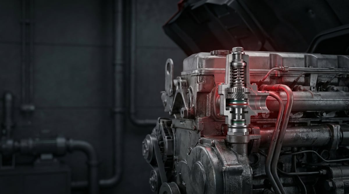
The pressure limiting valve is one of the quietest yet most critical components in a heavy commercial vehicle's air system. In the workshop it is often overlooked; on the chassis it is just a small, dusty brass body with the paint flaking off. But one day the parking brake starts to release slowly, the suspension bellows works harder than expected, or a hose bursts on an auxiliary circuit — and the trail keeps leading back to this valve. Referred to in German technical documents as the Druckbegrenzungsventil (DBV), this part appears under that name on everything from the product label to the service manual on European tractor units and trailers. This guide was written to help you recognise the valve in the field, diagnose its faults correctly, replace it without error, and extend its service life.
E-E-A-T note: This document was prepared by the VADEN technical team, drawing on hands-on heavy commercial vehicle air system application experience and OE service documentation. The figures here are typical ranges that vary with the make, model, chassis configuration and circuit design. For the exact set pressure, torque and interval, always rely on the vehicle manufacturer's current service manual. Last updated: September 2026.
Heavy commercial vehicle air brake systems are designed within the framework of ECE R13 (UN/EU braking regulation) and ISO 611.What Is a Pressure Limiting Valve? Function and Operating Principle
The pressure limiting valve (Druckbegrenzungsventil) is a mechanical control valve that, in a heavy commercial vehicle air system, limits the pressure of a sub-circuit so that it never rises above a preset upper value, regardless of the pressure in the supply line.
The logic is simple: a tractor unit's main air reservoir typically operates around 10–12.5 bar. But not every consumer in the system can withstand that pressure or needs it. The cab suspension, seat bellows, differential lock actuator, exhaust brake cylinder, horn, PTO circuit, door/lock auxiliaries — each of these works most efficiently and lasts longest at its own design pressure. This is exactly where the pressure limiting valve comes in: it takes the high-pressure supply and delivers a stable, safe ceiling pressure at its outlet.
Inside the valve there is essentially a spring, a piston (or diaphragm) and a sealing kit. The valve stays open and lets air through until the outlet pressure reaches the set value determined by the spring preload. The moment the set value is reached, the piston overcomes the spring force, moves towards the seat and closes off the passage. When the outlet-side pressure drops due to consumption, the spring pushes the piston back and the valve opens again. In other words the valve does not constantly "open and shut"; it works in a modulation that seeks equilibrium. That is why a small hysteresis (the difference between the opening and closing pressure) always exists around the set pressure, and this is normal.
- Body: Usually brass or die-cast aluminium; the inlet (1) and outlet (2) ports are, in most applications, M12×1.5, M16×1.5 or M22×1.5 thread standard.
- Setting spring: The main element that determines the limiting pressure. Fatigue = drift of the set pressure.
- Piston / diaphragm: The moving element that balances the pressure force against the spring force.
- Valve seat: The sealing face. A scratch, dirt or corrosion = continuous leakage.
- O-ring and sealing kit: NBR or EPDM based; heat and oil resistance are decisive here.
- Adjusting screw and lock nut / cap: Found on adjustable types; fixed types have a pressed-on cap.
- Exhaust port (on some types): A safety function that vents excess pressure to atmosphere.
Is a Pressure Limiting Valve the Same as a Pressure Regulator?
No — and this is the most commonly confused topic in the field. The pressure regulator (Druckregler) sits at the compressor outlet, manages the main system pressure and unloads the compressor when the cut-out pressure is reached. The pressure limiting valve, by contrast, protects not the main system but a sub-circuit; it does not communicate with the compressor, it only limits the pressure at its own outlet. There is also the safety valve (Sicherheitsventil / Überdruckventil): that is normally fully closed and only vents air when a dangerous overpressure occurs. The pressure limiting valve, on the other hand, continuously passes air during normal operation. These are three different jobs, and one cannot be fitted in place of another.
Adjustable and Fixed-Setting Types
Fixed-setting types are calibrated to a factory-determined value and sealed; they are not meant to be tampered with. Adjustable types have an adjusting screw on the top cap — as the screw is tightened, the spring preload and therefore the limiting pressure increase. Adjusting an adjustable valve "by eye" in the field is both dangerous and pointless; it must always be done with a calibrated pressure gauge and according to the target value in the service manual.
Types with a Reverse-Flow Function
In some applications the valve incorporates a bypass or check function that allows the outlet-side pressure to flow back towards the inlet side. This is particularly important in cab suspension and auxiliary reservoir circuits. When a valve without a reverse-flow feature is fitted to such a circuit, the system appears to "work", but the driver starts to complain of stiffening in the cab, slow venting or residual pressure trapped in the bellows. That is why not only the set pressure but also the function type must match.
| Application / Circuit | Typical Vehicle Group | Typical Limiting Range | Note |
|---|---|---|---|
| Cab suspension circuit | European tractor units (4×2 / 6×2) | ~6–8.5 bar | Usually a reverse-flow type |
| Seat bellows / driver comfort circuit | Tractor unit and bus | ~6–8 bar | Low flow, sensitive setting |
| Differential lock actuator | Construction / off-road trucks | ~6–8.5 bar | Actuator design pressure is decisive |
| Exhaust brake / engine brake cylinder | Truck and bus | ~5–8 bar | Wide variation by application |
| Auxiliary / equipment (PTO, body) | Tipper, crane, tractor bodywork | ~6–10 bar | Bodybuilder specification governs |
| Trailer supply auxiliary circuits | Semi-trailer / trailer | ~6.5–8.5 bar | Refer to the trailer manufacturer's manual |
Part number verification is essential. The table above is for guidance; do not read any row as "this vehicle has this pressure." Two different chassis codes of the same tractor model may use valves with different settings. To select the correct part: (1) the vehicle chassis/VIN number, (2) the OE number and set-value stamp on the body of the removed valve, (3) the function type of the circuit (reverse-flow / non-reverse-flow), (4) the port thread and body geometry — check all four together. Knorr-Bremse, WABCO/ZF, Haldex, Bendix equivalent/type references are for cross-reference purposes only; final approval rests with the vehicle manufacturer's catalogue data.
Fault Symptoms and Diagnosis
Pressure limiting valve faults rarely arrive with a "bang." They usually creep up slowly: first it engages a fraction late in the mornings, then it becomes pronounced in the cold, and finally the circuit becomes completely unusable. The table below summarises the symptoms most frequently encountered in the field, their likely sources and the distinguishing checks.
| Symptom | Possible Cause | Check / Verification |
|---|---|---|
| Outlet pressure stays below target; the circuit works weakly | Setting spring fatigued / collapsed, piston stuck with dirt, internal passage blocked | Connect a calibrated gauge to the outlet port; with the system at full pressure, read the outlet value and compare it with the target range in the service manual |
| Outlet pressure exceeds the set value; bellows/actuator excessively stiff | The valve is not closing: seat scratched, piston jammed in the open position, foreign object | Monitor the circuit pressure with a gauge; if it keeps rising together with the system pressure, the valve is not limiting |
| Continuous air leak from the valve body or cap | O-ring hardened/torn, cracked body, leaking adjustment cap | With the system pressurised, scan the body, cap and port areas with soapy foam; isolate the leak point |
| Continuous air from the exhaust port (on vented types) | Loss of internal sealing, seat damage, broken spring | Check the exhaust port with a finger (care — under pressure); a continuous flow means the valve is leaking internally |
| Late or no operation only in cold weather, improving once warm | Frozen condensate / ice inside, loss of dryer performance, elastomer hardening | Check the air dryer and the reservoir drain; if water comes from the reservoir, the root cause is the dryer, not the valve |
| Compressor running time increased, cycling frequency higher | A valve-induced leak is continuously bleeding the system | Engine off, system at full pressure: monitor the main reservoir drop over 10 minutes; then isolate the valve and repeat the test |
| Outlet pressure fluctuates, unstable (actuator judders) | Wear in the piston guide, broken spring, dirt-related stick-slip | Fill and vent the circuit a few times while watching the gauge; if the needle swings, there is internal mechanical instability |
| The circuit does not vent, pressure is held permanently | A valve without a reverse-flow function has been fitted, or the bypass is blocked | Compare the type and OE number of the removed original part with the fitted part |
Accurate Measurement with a Gauge
The backbone of diagnosis is the gauge, not the cab display. Cab gauges usually show the main circuits and do not tell you the real pressure of an auxiliary circuit. Connect a calibrated gauge to the nearest test point to the valve outlet (a test coupling if there is one, otherwise via a suitable T-fitting). Take the reading after the system has reached full pressure, with the engine stopped and the pressure settled. Compare the reading with the target in the service manual; if it is out of tolerance, the valve is suspect.
Isolating the Leak
Chasing a leak in an air system is a process of elimination. Cap the inlet of the suspect valve with a blanking plug; if the leak continues, the problem is not the valve but further along the line. If the leak stops, the valve or the connecting fitting is responsible. One step further: you can remove the valve and pressurise it on the bench (with suitable equipment) to see the internal leakage directly. Soapy foam is simple but still the most reliable method.
What to Rule Out Before Blaming the Valve
The pressure limiting valve often takes the blame for problems that precede it. Before replacing it, rule these out: is the air dryer cartridge saturated (moisture may be getting inside the valve), are the reservoir drain valves working, has the compressor's efficiency dropped (the main pressure may already be failing to reach target), are there kinks/crimps in the lines, is the four-circuit protection valve feeding its own circuit correctly. If the main supply cannot even reach 8 bar, replacing the valve that limits to 8 bar fixes nothing.
Standards and further reading
This subject is governed by the equipment rules for air-braked commercial vehicles. In the United States the federal air brake standard, FMVSS 121 (49 CFR 571.121) defines the reservoirs, protection and timing a compliant system must provide, and Europe applies the equivalent limits of UNECE Regulation No. 13. For further detail, see the illustrated reference guide at airbrakecompressor.com. Always confirm specific figures against the current regulation and the vehicle manufacturer service data.
Outside the United States the equivalent duties sit in national law. In the United Kingdom, regulation 18 of the Road Vehicles (Construction and Use) Regulations 1986 requires every part of the braking system to be maintained in good working order. In Canada, air brake systems fall under the Motor Vehicle Safety Regulations, which contain CMVSS 121.
Replacement / Installation Steps
Safety and PPE. Compressed air can be fatal. Before starting work: stop the engine, switch off the ignition, chock the vehicle, secure the parking brake appropriately and fully vent the relevant circuit (with test brake applications and reservoir drains). Wear safety glasses, work gloves and hearing protection. Never loosen a fitting under pressure — a fitting that shoots off, together with dust, causes permanent eye injury. If you are working on a suspension or lifting circuit, do not go underneath the vehicle without securing it with mechanical supports. If in doubt, stop work and refer it to an authorised service.
- Confirm the fault: Before removing the part, prove that the valve is really responsible using a gauge measurement and leak isolation. Replacing a part on a guess costs both money and trust.
- Prepare the correct spare part: Match by chassis/VIN, the OE number of the valve to be removed, the set-pressure stamp, the port thread and the function type. Have the new part in hand before you start work and compare its body stamp side by side with the old part.
- Fully vent the circuit: Engine off, ignition off. Vent the relevant circuit and confirm it is at 0 bar by reading a gauge. "It's probably vented" is not a verification method.
- Document the mounting position and line direction: Take a photo before removal. Label the inlet/outlet ports (usually 1 = inlet, 2 = outlet). Mixing up the lines makes the valve work in the wrong direction and leaves the circuit completely unprotected.
- Remove the lines and protect the openings: Loosen the fittings with the correct spanner while counter-holding the body. Cap the removed hose ends with clean plugs or tape; once chassis dust gets into a line it will damage the seat of the new valve too.
- Remove the valve and inspect the old part: Note the corrosion on the body, water inside, oil deposits and swarf/rust particles. These findings tell the root cause: if water is coming from inside, look at the dryer; if black oily sludge is coming out, look at the compressor.
- Clean the mating surface and the lines: Completely remove old seal/PTFE residue from the thread face. Connecting a dirty line to a new valve brings the same fault back a few thousand kilometres later. If necessary, clean and dry the line with compressed air.
- Fit the new valve with the correct sealing: Use the seal/O-ring or thread-sealing method specified by the manufacturer. Do not overwrap PTFE tape and leave the first 1–2 turns of the thread start bare — a piece of tape can get inside the valve and damage the seat. If a sealing liquid is used, observe the curing time.
- Tighten to the specified torque: First fit by hand without cross-threading, then tighten to the specified torque. Excessive torque on a brass body = a cracked body and repeat work. Tighten the fittings while counter-holding the body; tightening by twisting the body strains the internal mechanism.
- Charge the system and carry out a leak test: Start the engine and bring the system to full pressure. Check all connections, the body and, if present, the exhaust port with soapy foam. Then stop the engine and repeat the pressure-drop test.
- Verify the function and the set value: Read the outlet pressure with a gauge; is it within the manual's range? Operate the circuit a few times (fill and vent the bellows, trigger the actuator) and confirm the behaviour is stable. If you have made an adjustment on an adjustable type, secure the lock nut and re-read after the road test.
Points to Watch (Common Mistakes)
The most expensive mistake: skipping the root cause. If you are replacing the pressure limiting valve for the second time on the same vehicle, the problem is not the valve. The air dryer is saturated, the compressor is passing oil, or the reservoir drain is not working. Moisture and oil entering the system will end the life of the new valve the same way, no matter which brand you fit. On the second failure, put the air preparation group on the table, not the valve.
There is no such thing as an "about the same" valve. A valve that fits the thread and looks similar in body but whose set pressure is 1 bar off does not protect the system — it merely delays the fault and usually takes a more expensive part (bellows, actuator, cylinder) with it. Fitting a non-functional valve to a reverse-flow circuit falls in the same category: the installation holds, the system does not.
- Turning the adjusting screw "by feel": Any adjustment made without a calibrated gauge is a guess. On sealed/fixed types, attempting to adjust scraps the part outright.
- Excessive torque: A cracked brass body is the most common cause of "the new part failed immediately" in the field. Follow the specified torque and do not use a power tool.
- Over-wrapping and misapplying PTFE tape: Tape wrapped right to the thread start gets inside and damages the seat. The direction of the tape must also follow the thread-tightening direction.
- Connecting the lines backwards: When inlet/outlet are mixed up, the valve often appears to "pass air" but does not limit. Photo and label before removal.
- A clean part on a dirty line: Rust, swarf and dry seal residue in the line go straight into the new valve on the first pressurisation.
- Dismantling without releasing pressure: The most common cause of injury. Do not loosen any fitting until the gauge reads 0.
- Treating a leak as "acceptable": A small air leak runs the compressor constantly; it increases fuel consumption, compressor temperature and the amount of oil entering the system. A small leak is the early bill for a big failure.
- Reusing a coupling/fitting seal: A seal that has been tightened once has taken a permanent deformation. New valve, new seal.
- Leaving the valve unprotected during welding/painting: Splashing slag and paint quietly finish off the seat and the elastomer.
Technical Values and Check Points
The values below are of a typical / general reference nature for heavy commercial vehicle air systems. They vary with the make, model, chassis code and circuit design; for the exact value, the vehicle manufacturer's current service manual governs.
| Parameter | Typical Range (general reference) | Explanation |
|---|---|---|
| Main system operating pressure | ~8.0–12.5 bar (≈116–181 psi) | Cut-out/cut-in pressure is set by the regulator |
| Auxiliary circuit limiting pressure | ~5.5–8.5 bar (≈80–123 psi) | Application-specific; the stamp on the valve body is decisive |
| Setting tolerance | Generally ±0.2–0.5 bar | If the manual gives a narrower tolerance, that applies |
| Hysteresis (opening–closing difference) | ~0.2–0.6 bar | A small difference is normal; a large difference indicates internal wear |
| Maximum permissible inlet pressure | Typically ~12.5–13 bar class | Do not exceed the label/catalogue value |
| Operating temperature range | ~ −40 °C … +80 °C | Varies with the elastomer type (NBR / EPDM) |
| Test pressure drop (isolated circuit) | On the order of ~0.1–0.2 bar in 10 minutes | Acceptance criterion per the manual; a marked drop = leak |
| Port thread standard | M12×1.5 / M16×1.5 / M22×1.5 (common) | Different threads and geometry may apply by application |
| Connection | Typical Torque Range (general reference) | Note |
|---|---|---|
| M12×1.5 fitting / port | ~20–30 Nm | Stay near the lower limit on a brass body |
| M16×1.5 fitting / port | ~30–45 Nm | Tighten while counter-holding the body |
| M22×1.5 fitting / port | ~40–60 Nm | Varies with the seal type |
| Bracket / body mounting bolt (M8) | ~20–25 Nm | Depends on the chassis bracket design |
| Adjusting screw lock nut | ~8–15 Nm | Must be secured without disturbing the setting |
Field tip: Torque values are given for dry, clean threads. When a thread-sealing liquid or tape is used, friction drops, and at the same torque the actual stress rises — on a brass body that means a crack. If you use a sealing compound, start from the lower end of the specified range and tighten in stages if there is a leak. Also, always read the system pressure with a calibrated gauge; the cab display is an information tool, not a diagnostic tool.
- Body stamp: Do the OE number and set-value stamp of the removed and fitted valve match exactly?
- Outlet pressure: With the system at full pressure, is the outlet within the manual's range and stable?
- Leak: Are the body, cap, fittings and exhaust port clean under soapy foam?
- Static test: Engine off, is the pressure drop over 10 minutes within the acceptance limit?
- Condensate: Is water/oil coming from the reservoir drain? If so, the dryer and compressor are next in line.
- Mechanical: Is the bracket sound, are the lines not under tension, is there no chafing point under vibration?
- Function: Does the circuit fill and vent repeatably over several cycles?
Maintenance and Service Life
By design, the pressure limiting valve is not in the "lubricate, adjust, clean" group; it is not a part that is periodically dismantled and serviced but a part whose condition is monitored. What determines its life is not the valve itself but the quality of the air passing through it. A valve fed with clean, dry, oil-free air works trouble-free for hundreds of thousands of kilometres; the same valve fed with damp, oily air is finished in a few seasons. That is why valve maintenance is really air-preparation-group maintenance.
- Replace the air dryer cartridge on schedule. The dryer is the air system's immune system; from the moment it is saturated, moisture goes straight to the valves. On Knorr-Bremse, WABCO/ZF, Bendix equivalent/type dryers the interval varies with usage intensity and climate — follow the manual.
- Drain the reservoirs regularly. Water coming from the reservoir during a routine check is the dryer's message. Be sure to carry out this check before winter.
- Monitor the compressor. A compressor carrying oil into the air system swells the elastomer seals and fouls the seat. If you see black oily deposits in the system, the root cause is upstream.
- Make the leak test routine. Engine off, a 10-minute pressure-drop test; simple, quick, and the measurement that gives the earliest warning.
- Prepare for winter. Frozen condensate is the most common factor that mimics a valve failure. Before the cold, check the dryer + drain + leak trio.
- Check the mechanical load. A taut hose, a broken bracket and vibration fatigue the valve body; they slowly create a leak at the port thread.
- Replace rather than repair. On heavy commercial vehicle safety circuits, "opening up and cleaning" a valve whose calibration has drifted is a risk dressed up as a saving. No repair that cannot be verified without calibrated test equipment is safe.
In short: the valve is your system's health report. Acting early prevents the cost of the bellows, actuator and cylinder — which are far more expensive than the valve itself — and, most importantly, vehicle downtime. When you see a valve that has failed unexpectedly early, ask the question "what killed this valve?" once before fitting the new part and driving on.
The VADEN ORIGINAL Pressure Limiting Valve product family is manufactured with the real operating conditions of heavy commercial vehicle air systems in mind — high cycle counts, a wide temperature range, vibration and variable air quality. To select the valve with the correct set value, function type and port geometry for your vehicle, query the VADEN catalogue with the OE part number; when in doubt, consult the VADEN technical team with your chassis/VIN information. The right part, the right pressure, the right installation — the life of the air system is hidden in these three.
Related categories: Pressure Limiting Valve · Pressure Limiting Valve · Repair Kit
Related technical guides: ABS Wheel Speed Sensor & ECU: Faults, Replacement & Care · Brake Caliper Overhaul Kit: Guide Pins, Boots & Adjuster · Air Processing Unit (APU/EAC): Faults, Replacement & Care · Four-Circuit Protection Valve: Faults, Diagnosis & Replacement · ALB Load Sensing Valve: Faults, Replacement & Setting Guide
Application and compatibility: Vehicle compatibility catalogue · Engine compatibility catalogue
Main guide: Truck Air Brake Valves Explained: Types, Functions and Failure Symptoms
Tags
Frequently Asked Questions
- If the pressure limiting valve fails, can the vehicle stay on the road?
- It depends on which circuit it feeds, and the decision belongs to the vehicle manufacturer's manual. If it limits a circuit related to brake safety, the vehicle should not be driven. Even if it is a comfort circuit (cab/seat suspension), a valve-induced leak can run the compressor constantly and lower the main system pressure — so a fault thought to be "just comfort" can indirectly affect brake performance. The right approach: fix the fault without delay.
- Is the Druckbegrenzungsventil the same as a pressure limiting valve?
- Yes. The Druckbegrenzungsventil (DBV for short) is the German equivalent of the pressure limiting valve and appears under that name in documents for European tractor units, buses and trailers. In Turkish catalogues you will see "basınç sınırlama valfi", and in English documents generally "pressure limiting valve." The same part, three languages.
- What is the difference between a pressure limiting valve and a safety valve?
- The pressure limiting valve continuously passes air during normal operation and holds the outlet pressure at a ceiling value. The safety valve (Sicherheitsventil), by contrast, is normally closed; it opens only at a dangerous overpressure to vent air to atmosphere — in other words it is the last line of defence. Their jobs differ, and they are not used in place of one another.
- Can I change the valve's set pressure myself?
- On fixed/sealed types, no. On adjustable types, only with a calibrated gauge, according to the target value in the service manual, and locking it after adjustment. An adjustment by eye exposes the actuator or bellows in the circuit to excessive pressure; the resulting damage is many times more expensive than the valve.
- How do I find out how many bar my vehicle's pressure limiting valve is?
- The three most reliable sources: (1) the stamp/label on the valve body, (2) the vehicle manufacturer's chassis/VIN-based service manual, (3) a catalogue query via the OE part number. Forum information or a "the same-model truck had this" approach is not enough — the same model may carry a different setting on a different chassis code.
- How often is a pressure limiting valve replaced?
- There is no fixed mileage interval; it is a condition-based part. The main factor determining its life is air quality. In practice: in a system whose dryer is replaced on schedule and whose reservoirs hold no water, the valve works for many years. In a system pushing damp/oily air, it fails early and fails repeatedly.
- Is it more sensible to repair or replace a leaking valve?
- On a heavy commercial vehicle air system, replace. Putting a valve whose calibration has drifted back into service without verifying it on the bench means returning an undiagnosed risk to the vehicle. The cost of the new part is small next to a second roadside failure and the downtime.
- There is an air leak in the system but I can't find its source, where should I start?
- With the elimination method. Do a 10-minute drop test at full pressure with the engine off; then, by isolating the circuits one by one (with a blanking plug/coupling), narrow down which branch the drop is in. When you reach the suspect branch, scan the body, cap, fitting and exhaust port with soapy foam. Because of vibration, the leak is usually at the base of the fitting and only visible under pressure.
- The valve I just fitted failed again quickly, why?
- Three classic reasons: the wrong part (set value or function type mismatch), an installation error (excessive torque, a piece of PTFE, backwards connection) or the root cause still being present (saturated dryer, oil-passing compressor). Rule out all three; the third is the one most often skipped.
- I fitted a valve with the correct set pressure but the cab bellows still vents late; can the part still be wrong?
- Yes. Some cab suspension and auxiliary reservoir circuits need a valve with a bypass or check function that lets outlet-side pressure flow back towards the inlet. Fit one without that feature and the installation holds and the system appears to work, but the driver reports cab stiffening, slow venting or residual pressure trapped in the bellows. Match the function type as well as the set pressure; the OE number on the removed valve settles it.
Related Articles

ABS Brake System: How It Works, Warning Light and Faults
Learn how the ABS brake system works on heavy trucks, why the warning light comes on, how to diagnose sensor faults, and the correct replacement steps.
Brake Chamber, Diaphragm & Hose: Faults, Replacement, Care
Learn how to spot a leaking brake chamber, measure push rod stroke, cage the power spring safely and replace the unit and hose without risk on heavy trucks.
Air Dryer Purge Valve: Faults, Replacement and Maintenance
How a truck air dryer purge valve works, spotting leak and freezing symptoms, safe step-by-step replacement and keeping the air brake system dry.


