Truck Air Brake Valves Explained: Types, Functions and Failure Symptoms
Truck air brake valves explained: what relay, ALB, foot brake and trailer valves do, their failure symptoms, and how to diagnose faults with a pressure gauge set.
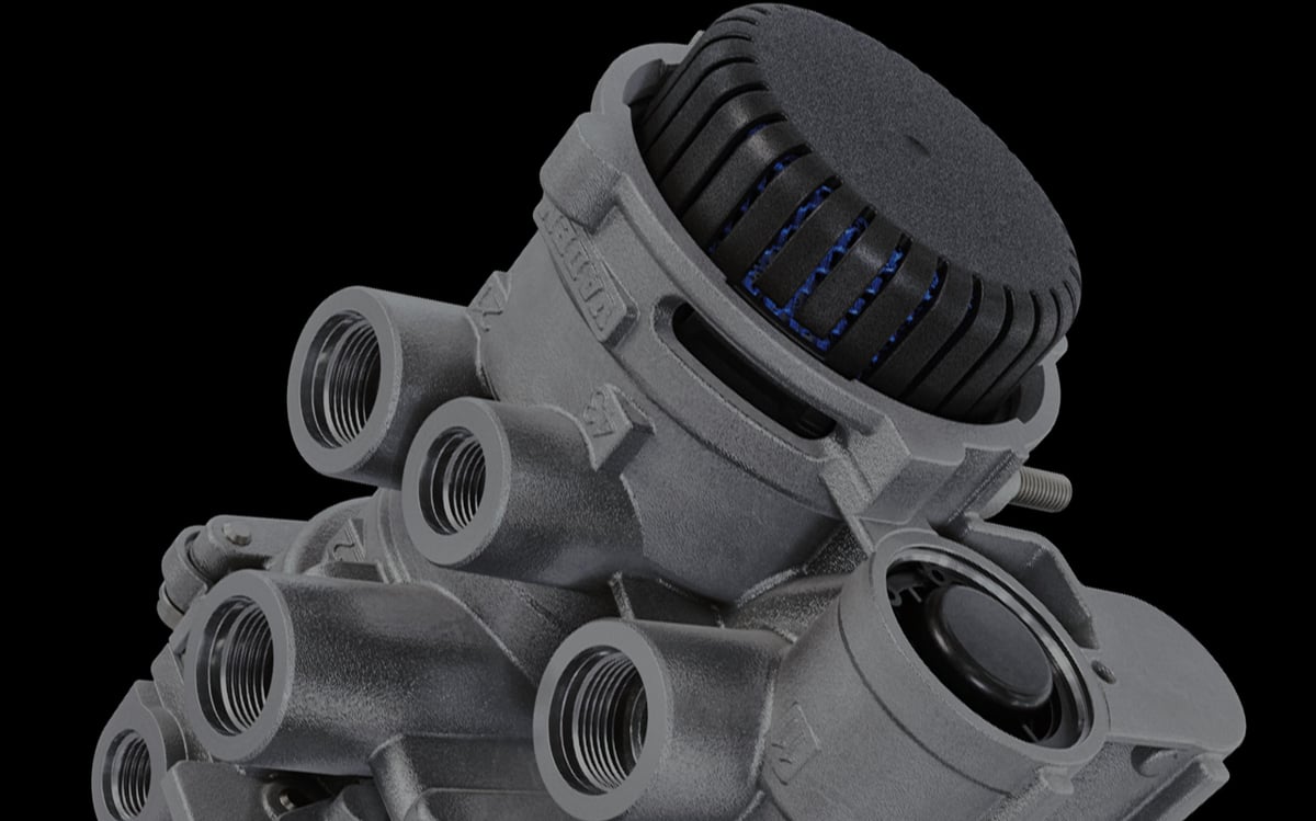
A fully loaded tractor unit makes the driver uneasy at the very first junction: the pedal doesn't sit where it should, it sinks a little deeper than usual, and the trailer can be felt pushing from behind. Both gauges on the dash read full, the compressor is charging, and the reservoirs hold pressure. Once the shop measures the circuit point by point, the picture clears up: the foot brake valve builds correct pressure at its own outlet, but the rear-axle relay valve delivers it late and short at its outlet. The faulty part is small enough to fit in a palm and has nothing to do with the compressor or the air springs. An air brake system has exactly one component that generates air; the valves that send that air to the right place, at the right moment, at the right pressure number in the dozens. This guide treats the valves in the brake circuit not as a parts list but as a connected control network — mapping where each valve sits, what job it does, and what symptom it produces when it fails.
Why does an air brake system need so many valves?
A valve is the control element that opens, closes or redirects the path of pressurised air, or holds an output pressure at a value different from its input. In a brake circuit a valve's job is not limited to acting like a tap: it also has to turn the force in the driver's foot into a pressure signal, carry that signal metres away, amplify it locally, scale it to the load on the axle, and drop the system to the safe side the moment something fails.
In a hydraulic brake the fluid cannot be compressed, so force reaches the calipers with almost no delay. Air behaves the opposite way: it is compressible, and once you factor in a tractor coupled to a trailer, the distance between the pedal and the rearmost chamber can run past fifteen metres. If the foot brake valve had to fill every chamber directly from its own outlet, the rear axle and the trailer would visibly lag behind the front axle. That is why the system is not built as one single line but as a small-flow signal layer paired with a power layer fed locally at each axle — and every transition between the two is a valve.
The second reason is regulatory. Type-approval rules for heavy vehicles require the service brake to be split across at least two independent circuits, the park brake to be fed separately, the trailer to be able to brake on its own, and a fault in one circuit to never drain the others. Protection valves, check valves and selector valves are what enforce this separation. The third reason is load: apply a loaded-axle brake force to an empty tractor's rear axle and the wheel locks; apply an empty-axle setting to a fully loaded axle and stopping distance stretches dangerously. Put together, valves fall into five families: those that regulate pressure, those that protect circuits, those that turn a command into a signal, those that amplify and apply that signal, and those that carry out a safety function.
Circuit logic: supply, storage, control and application layers
The circuit looks complicated, but read it as four layers and every valve's place becomes obvious. The rule for reading any schematic is simple: you cannot judge a valve without knowing what sits at its inlet and where its outlet actually goes.
The supply layer produces air and makes it usable — the compressor, the pressure regulator, the air dryer and the multi-circuit protection valve live here. The storage layer covers the wet tank, the service-circuit reservoirs, and the park and trailer reservoirs; check valves at the reservoir inlets stop a leak in one circuit from draining the neighbouring reservoir. The control layer converts the driver's or the electronics' intent into a pressure signal: the foot brake valve, the hand brake valve, the trailer control valve and the load sensing valve sit here; the air volume they produce is small, they do no work, they carry information. The application layer takes that signal and pulls a large flow of air from the reservoir right next to it to fill the chambers: relay valves, ABS modulators, quick release valves and the trailer brake valve.
This split is the backbone of diagnosis. A fault in the signal layer is usually seen across an entire circuit, proportionally; a fault in the application layer shows up at a single axle or a single side. So when a driver says "the brakes aren't holding," the first question to ask is which wheels are actually affected.
Control valve vs. application valve — what's the difference?
Two valves with near-identical housings can do completely different jobs. The most practical way to tell them apart is to look at where each one gets its air: a control valve builds its output from the air passing through its own body, while an application valve uses the signal purely as a reference and draws its air from the reservoir beside it.
| Criterion | Control valve | Application valve |
|---|---|---|
| Primary role | Turns a command into a metered pressure signal | Amplifies the signal with local air and applies it to the chamber |
| Where its air comes from | Its own inlet port, through a thin line | The nearby reservoir, through a thick supply line |
| Flow it passes | Small — only enough to fill the signal line | Large — fills chamber volume quickly |
| Typical examples | Foot brake valve, hand brake valve, load sensing valve | Relay valve, ABS modulator, quick release valve |
| Scope of the symptom | Affects the whole circuit it feeds | Usually limited to one axle or one side |
| Diagnostic approach | Output pressure tracked against pedal position | Signal inlet compared against delivery pressure |
Map of air brake valves: what sits where, and what does it do?
The table below lists the valves most commonly found in a brake circuit, grouped by layer. Depending on the vehicle maker, some of these may be combined into a single housing; a function that is a separate part on one model can live inside a module on another. When reading the map, follow the job the part does rather than the name on it.
| Valve | Where in the circuit | Function | What happens when it fails | Typical symptom |
|---|---|---|---|---|
| Pressure regulator | Between compressor and dryer | Holds system pressure at an upper limit, unloads the compressor | Pressure doesn't build, or runs up against the safety limit | Slow pressure build-up, safety valve blowing off |
| Multi-circuit protection valve | Between dryer outlet and reservoirs | Distributes air by priority, isolates a faulty circuit | A leak in one circuit drains the whole system | All gauges dropping from a single leak |
| Check valve | Reservoir inlets and circuit crossovers | Lets air flow in one direction only | Reverse leakage forms, neighbouring circuit drains | Pressure dropping overnight while parked |
| Foot brake valve | Under the cab, control layer | Converts pedal force into a proportional signal for two circuits | Signal is produced late, short, or interrupted | Pedal sinking deeper, hiss from the exhaust |
| Relay valve | Near the axle it controls | Amplifies the signal with reservoir air, speeds up fill and exhaust | Brake applies or releases late | Dragging, hot drum, timing mismatch between axles |
| Load sensing (ALB) valve | Rear-axle line, control layer | Scales brake pressure to axle load | Too much pressure empty, too little loaded | Lock-up empty, insufficient braking loaded |
| Quick release valve | Close to the chamber, application layer | Dumps chamber air by the shortest path on release | Brake releases late, residual pressure remains | Pad or lining drag, overheating, higher fuel use |
| Hand brake (park) valve | In the cab, control layer | Vents or restores pressure in the spring brake line | Park brake won't set or won't release | Lever not holding, spring brake releasing late |
| Spring brake relay valve | Rear-axle area | Amplifies the park signal, vents spring chambers quickly | Spring brake releases late or stays applied | Resistance pulling away, hot drum, partial drag |
| Double check (selector) valve | Where two control lines meet | Selects and passes through the higher of two signals | Backup control path is disabled | Trailer not braking with the hand brake |
| Trailer control valve | On the tractor, control layer | Sends the service and park command to the trailer control line | Trailer command arrives short or not at all | Trailer holding late or not braking at all |
| Trailer brake valve | On the trailer, application layer | Fills chambers on signal, brakes automatically if supply is lost | Breakaway protection fails, or brake stays applied | Detached trailer not braking, or staying braked |
| ABS modulator valve | Between relay valve and chamber, or combined with it | Holds, dumps and rebuilds pressure during lock-up | Lock-up control is lost, base braking remains | ABS warning lamp, a single wheel locking |
The most instructive rows on this map are the ones most often mixed up: a relay valve and a quick release valve can share a similar housing, yet one draws air from a reservoir while the other only vents the air already sitting in the chamber.
Supply and protection group valves
The health of the brake circuit is decided before a single brake application happens. Faults in this group usually don't show up as "the brakes aren't holding" — they show up as "pressure won't build."
The pressure regulator keeps system pressure between two thresholds: at the upper one it unloads the compressor, at the lower one it puts it back to work. In a heavy commercial vehicle, working pressure is generally held in a band of roughly 8 to 12.5 bar; the exact cut-out and cut-in figures are vehicle-specific and should be read from the OE manual. When the regulator cuts out late, the safety valve vents air outward; when it cuts out early, the reservoirs never fill fully and pressure runs down fast under repeated braking.
The air dryer and its purge valve keep moisture and oil out of the system. A leaking purge valve causes continuous air loss; one that never opens prevents the dryer from regenerating, which carries moisture into the reservoir and from there into every downstream valve. A large share of sticking and internal-leak faults in brake valves traces back to this water.
The multi-circuit protection valve distributes air by priority and isolates a circuit the moment it develops a leak, protecting the pressure in the others; the service brake circuits are generally the first to fill, with auxiliary consumers left for last. When this valve fails, a single burst hose can immobilise the entire vehicle. In a system that's full in the morning but flat by evening, the protection valve and the check valves at the reservoir inlets are among the first places to look.
Foot brake valve: the valve that produces the control signal
The foot brake valve translates the force in the driver's foot into the language the system understands. In a heavy commercial vehicle this valve is built in two stages; its upper and lower sections independently feed two separate service circuits. The goal isn't just to open and shut off air — it's to build a proportional, repeatable relationship between pedal travel and output pressure. This is called graduated control, and it's what lets the driver feel how hard they're braking.
What creates that feel is the reaction surface inside the valve: the pressure that forms at the output pushes a piston back and generates a counter-force at the pedal. That's why a change in pedal feel is, on its own, a fault symptom; in an air system, extra pedal travel isn't something you fix by bleeding the way you would with hydraulics — it's a sign that a spring, piston or seal inside the valve has worn out.
The second purpose of the dual-circuit design is safety: if one circuit leaks, the valve's other section keeps being actuated mechanically, and the vehicle can still be stopped with reduced but usable braking. The most common fault is a continuous hiss from the valve's own exhaust port, which points to an internal seal starting to leak. Pressure that stays at the output even after the pedal is released is more dangerous, because it creates a drag that goes unnoticed. This valve's symptoms, the discipline of removal and refitting, and its adjustment points are covered step by step in the foot brake valve guide.
Relay valve: the valve that shortens response time
The relay valve is, on its own, the reason air brake circuits are built the way they are. If the foot brake valve had to fill the rear axle's chambers through ten metres of pipe from its own outlet, fill time there would run noticeably longer than at the front axle. The relay valve splits the problem in two: the thin line coming from the pedal carries only a signal, while the air that actually fills the chambers comes from the reservoir right next to the valve, through a short, thick line. That way, fill time is set by the short connection between the relay valve and the chamber, not by metres of pipe.
The same logic applies on the release side: a wide exhaust port dumps the chamber's air locally, so that air never has to travel back through the pipe. This is the main reason the linings free up promptly the moment the brake is released.
Both functions show up separately when something goes wrong. If the fill side is slow, the brake applies late and a timing gap opens up between axles; if the exhaust side sticks, the brake releases late, the lining drags, the drum heats up, and fuel consumption rises. How the valve works, how it differs from an ABS relay valve, and the risk of mixing up ports during replacement are covered in detail in the relay valve guide. The diagnostic rule is clear: measure the control port and the delivery port at the same time — if control builds correctly but delivery lags behind, rises slowly, or doesn't fall once the pedal is released, the fault is in the valve.
Load sensing (ALB) valve and scaling brake force to load
A tractor's rear axle can carry several times more weight loaded than empty. If brake force doesn't adapt to that swing, one of two bad outcomes is unavoidable: a fixed pressure set for the loaded condition locks the wheel on an empty vehicle, while a pressure set for the empty condition dangerously extends stopping distance when loaded. The load sensing valve resolves this by scaling brake pressure to the load on the axle.
In mechanical setups, the valve measures the distance between the chassis and the axle through a lever-and-rod linkage; as load increases the chassis moves closer to the axle, and the valve allows a higher output pressure. On air-suspended vehicles the reading is taken directly from bellows pressure, since chamber pressure is already proportional to load. In electronic brake systems the information comes from a load sensor, and the scaling is carried out through the modulator in software.
The trickiest thing about this valve is that its failure can go unnoticed for a long time. A loosened lever linkage or a corroded joint doesn't trigger a dashboard warning — it just quietly distorts brake distribution. The symptom most often shows up through tyres and linings: single-point wear on the rear tyres when running empty, or front pads wearing out far faster when running loaded. A badly adjusted valve can produce a worse outcome than having none at all; fitting the part is only half the job, setting the lever's reference geometry to the OE value is the other half. Verification methods and the typical fitting mistakes are examined in the ALB load sensing valve guide.
Park and spring brake circuit valves
The park brake works the opposite way to the service brake. Braking force is produced not by air but by a powerful spring inside the chamber; air's job is to compress that spring and release the brake. The logic exists for safety: when the system loses pressure, the vehicle doesn't end up brakeless — it ends up braked.
The hand brake valve in the cab vents the spring brake line's pressure when the lever is pulled, and restores it when the lever is pushed back in. Many vehicles also have a control position, which lets you check whether the trailer holds while the tractor's own brake is released. The signal then travels to the spring brake relay valve at the rear, which takes on the job of rapidly filling and venting the large spring chambers; a park brake that releases slowly is more often traced back to this valve than to the hand brake valve.
The circuit's third element is the anti-compounding function. If the service brake is applied while the park brake is also set, the spring's force stacks on top of the chamber's force and pushes the mechanism past its design limit; a provision built into the system prevents this stacking, sometimes as a separate housing and sometimes built into the relay valve itself. The check valve at the park circuit's inlet protects park circuit pressure even if the service circuit develops a major leak.
Standards and further reading
This subject is governed by the equipment rules for air-braked commercial vehicles. In the United States the federal air brake standard, FMVSS 121 (49 CFR 571.121) defines the reservoirs, protection and timing a compliant system must provide, and Europe applies the equivalent limits of UNECE Regulation No. 13. For further detail, see the illustrated reference guide at airbrakecompressor.com. Always confirm specific figures against the current regulation and the vehicle manufacturer service data.
Outside the United States the equivalent duties sit in national law. In the United Kingdom, regulation 18 of the Road Vehicles (Construction and Use) Regulations 1986 requires every part of the braking system to be maintained in good working order. In Canada, air brake systems fall under the Motor Vehicle Safety Regulations, which contain CMVSS 121.
Trailer control valve and breakaway protection logic
The brake connection between a tractor and a trailer is made up of two lines. The supply line fills the trailer's own reservoir and signals that the system is live; the control line carries only a signal — how much braking the tractor is doing. The couplings for the two lines are shaped and coloured differently to prevent them being connected the wrong way round.
On the tractor side, the trailer control valve combines the service and park brake commands and sends them out on the trailer control line; when the hand brake is pulled, the trailer brakes too because this valve also factors in the park signal. On the trailer side, the trailer brake valve is an advanced version of a relay valve: it takes the signal and pulls a large flow of air from the trailer's own reservoir to fill the chambers.
This valve's second, critical function is breakaway protection. It continuously monitors pressure in the supply line; if a hose bursts, a coupling comes apart, or the trailer separates, supply pressure drops fast and the valve automatically applies the trailer brakes using whatever air remains in the trailer's own reservoir. This is exactly why a trailer that has come loose is able to bring itself to a stop.
The two complaints heard most often in the field sit at either end of this logic. With "the trailer isn't braking," the first check is whether the control line is carrying a signal, then whether the trailer valve's output is showing up. With "the trailer stays braked," the supply line pressure and the valve's safety section are examined instead, because the valve may be sensing a breakaway that isn't actually happening. In both cases, the coupling seals and hose ends should be checked before the valve itself is touched.
Small but critical valves: check valve, quick release, pressure limiting, double check
The cheapest parts in a brake circuit are often the ones that produce the most misleading faults; they go completely unnoticed while healthy, and when they fail they tend to throw the symptom onto a different part entirely.
The check valve lets air flow in one direction only, and sits at reservoir inlets, circuit crossovers and the park circuit's supply. When it fails, the pressure loss is slow and sneaky: the vehicle is left full in the evening, and by morning one or two circuits have dropped. Verifying the check valves before blaming the compressor or the dryer saves time.
The quick release valve sits close to the chamber, and its only job is to dump the chamber's air by the shortest possible path the instant the brake is released; when control pressure drops, its diaphragm shifts and chamber air vents straight to atmosphere. Once that diaphragm hardens or tears, the brake either releases late and starts to drag, or the valve leaks continuously while the brake is applied.
The pressure limiting valve caps output pressure at a fixed ceiling, generally on the front-axle line, to balance brake force between axles; when it fails, that balance between front and rear is upset. The double check (selector) valve compares the signals coming from two control lines and passes through the higher one, which is what lets the same brake line be commanded by either the foot brake or the hand brake. When this valve clogs, the backup control path is silently disabled: the vehicle brakes fine under normal use, but the trailer braking expected from the hand brake simply doesn't happen. This is why annual inspections test the hand brake position separately.
ABS and EBS: electro-pneumatic modulator valves
Classic pneumatic valves decide purely on pressure and spring force; ABS adds an electrically controlled layer on top of that. The ABS modulator valve sits between the relay valve and the chamber, or is combined with the relay valve in a single housing; its solenoids carry out three actions on command from the control unit — hold pressure, dump it, or rebuild it. When a wheel speed sensor reports a tendency to lock, this sequence can repeat many times per second.
In EBS applications, pedal movement is converted into an electrical signal first, and the axle modulators set pressure according to that signal; the pneumatic line remains as the backup path that takes over if the electronics fail. That's why a healthy pneumatic output from the foot brake valve stays essential even while the system is running in electronic mode.
The key diagnostic difference is this: electro-pneumatic valves log fault codes, classic valves don't. But those codes often point at the circuit, not the valve — behind a modulator fault code there's frequently a dirty wheel speed sensor or a corroded connector. Verifying the sensor signal before replacing the modulator avoids an unnecessary parts swap. When the ABS warning lamp is on, remember that base pneumatic braking continues; it's only lock-up control that has been lost.
Diagnostic flow: from symptom to valve
In air brake diagnosis, the most efficient route starts from the symptom, not the part. In the table below, the first check on every row is a measurement, not a parts swap; diagnosing by swapping parts is both expensive and misleading, because a healthy new valve can mask the real upstream fault for a while.
| Symptom | Valves to suspect first | First check |
|---|---|---|
| Pressure never builds, or builds very slowly | Pressure regulator, dryer purge valve, protection valve | Listen for continuous venting, read each circuit's pressure separately |
| Pressure drops from evening to morning while parked | Check valves, protection valve, reservoir drain cock | Monitor circuits individually, isolate the dropping one and search for the leak |
| One line fault drains every circuit | Multi-circuit protection valve | Check whether the healthy circuits' pressure is actually held |
| Brake applies late, trailer pushes from behind | Relay valve, trailer control valve, trailer brake valve | Monitor control and delivery pressures at the same time |
| Brake releases late, drum heats up | Relay valve exhaust, quick release valve, foot brake valve | Measure the residual pressure remaining after the pedal is released |
| Rear axle locks empty, brakes insufficient when loaded | Load sensing valve, pressure limiting valve | Compare lever position and empty/loaded output pressures against OE reference |
| Trailer doesn't brake at all | Trailer control valve, trailer brake valve, coupling seals | Check for signal on the control line, then whether the trailer valve delivers output |
| Trailer stays braked or overheats | Trailer brake valve safety section, double check valve | Measure supply line pressure and residual pressure in the control line |
| Park brake releases late, resistance on pull-away | Spring brake relay valve, hand brake valve | Monitor fill time and final pressure in the spring chamber line |
| Continuous hiss from the exhaust when the pedal is released | Foot brake valve internal seal | Confirm the hiss changes with pedal position to isolate it |
| ABS warning lamp is on | ABS modulator valve, sensor and wiring circuit | Read the fault code, verify sensor signal and supply first |
Pressure test points and diagnosis with a gauge set
The whole logic of diagnosis can be summed up in one question: which valve has the right pressure at its inlet, but not at its outlet? A test point is the small connection that lets you read line pressure without taking anything apart; you'll find one on every circuit, at protection valve outlets, at relay valve inlets, and on trailer lines. Several gauges are connected to these at once, because what you're really looking for is the difference and the timing between points, not an absolute value.
- Park the vehicle on level ground, chock it, shut the engine off, and record each circuit's static pressure.
- Start the engine and let the system build to full pressure; watch the fill time and the moment pressure cuts out to read the regulator's behaviour.
- Stop the engine and leave the brake untouched; watch each circuit's pressure drop rate separately — only one circuit dropping narrows down the leak's location.
- Connect gauges to both the control side and the delivery side of the valve under investigation; a reading from a single point is never enough on its own.
- Apply and release the pedal in stages; on a healthy valve, delivery follows control without delay and in proportion.
- Hold the pedal fully applied and wait; if delivery pressure drops, there's a leak inside the valve or in the chamber line.
- Release the pedal and time how long it takes delivery to reach zero; residual pressure is the most direct evidence of drag.
- On circuits with a load sensing valve, repeat the measurement both empty and loaded, and record the lever position each time.
- Read the trailer lines separately at the point on the tractor and at the trailer valve's output; losses caused by coupling seals show up here.
- Cap the test point connections once measurement is done, and carry out a low-speed brake check before driving off.
| Test point | General reference | Interpretation |
|---|---|---|
| Wet tank outlet | Working pressure is roughly a band of 8 to 12.5 bar | Cut-out and cut-in figures are assessed against the OE manual |
| Protection valve circuit outlets | Service circuits fill first, auxiliary consumers after | A circuit filling late or not at all points to a broken isolation |
| Relay valve control port and delivery | Delivery should follow control without delay | A slow rise or low delivery points to the valve itself |
| Trailer supply and control line | Supply should be close to the tractor's own circuit pressure | Residual pressure in the control line leaves the trailer permanently braked |
Valve fault or air leak?
A large share of air brake complaints aren't actually valve faults at all; an aged hose, a loosened fitting, a cracked plastic line or a worn coupling seal can produce exactly the same symptoms. The first rule for telling them apart is whether the leak depends on a particular state. A line leak is usually continuous and independent of position — if the line is pressurised, it leaks. An internal valve leak is usually state-dependent: it only appears while the pedal is pressed, only in a specific hand brake position, or only while a trailer is connected.
The second rule is where the leak exits: most valves vent air through their own exhaust or muffler once an internal seal fails, whereas a sound coming from the base of a fitting points to the line. The third rule is narrowing it down by isolation: if the loss persists once the trailer is disconnected, the search moves to the trailer side; if it stops, it moves to the tractor. The same goes for a relay valve — disconnect its output from the chamber and cap the chamber side; if the leak continues, it's the valve, if it stops, it's the chamber or the line.
Valve maintenance, service life and care during replacement
Brake valves don't have a fixed replacement interval; their lifespan is set not by mileage but by the quality of the air passing through them. Three things kill valves: moisture, oil and vibration. Water that reaches the inside of a valve freezes in winter and seizes the slides, and starts corrosion in summer; oil escaping from the compressor swells and hardens the seals. Which means genuine valve maintenance is the maintenance you do without touching the valve at all — replacing the dryer cartridge on schedule, draining the reservoirs regularly, and never ignoring an oil leak.
- Secure the vehicle on level ground, chock it, and bleed the circuit you'll be working on following the manufacturer's procedure.
- Label and photograph every line before removal; mixing up the control, supply and delivery ports on a multi-port valve is the most common mistake.
- Clean around the valve; sand and rust entering through the open ports puts the new valve at risk from day one.
- Don't force the fittings and don't bend the plastic lines; an aged line end can crack during removal and cause a leak later on.
- Cap every open port and hose end immediately; the system should never be left open.
- Compare the new valve against the old one: port count, port layout and mounting dimensions must match exactly.
- Renew the seals and any O-rings, and tighten the fasteners to the OE torque value with a torque wrench; over-tightening stresses the housing, under-tightening causes a leak.
- On parts that need adjustment, such as a load sensing valve, set the lever geometry to the OE reference — fitting the part is not the same as adjusting it.
- Refill the system, check the connections with a soapy solution, and read the control and delivery pressures again at the test points.
- On electronic systems, clear the fault codes and re-query them, run a low-speed brake test, and log the replaced part in the vehicle's file.
The most important rule to take from this valve map is that no valve in an air brake circuit can ever be considered in isolation. A sluggish relay valve can trace back to the foot brake valve, a trailer complaint can trace back to a coupling seal, and lock-up on an empty axle can trace back to the load sensing valve's lever setting. The correct order is always the same: first prove that clean air is being produced at sufficient pressure, then that the circuits are properly isolated, then that the control signal is correctly generated, and only last, that the application valve correctly translates that signal. Across every value given here, the vehicle's current OE service manual for its specific engine and chassis code remains authoritative.
The control group that carries the braking command between tractor and trailer deserves separate treatment; for symptoms, replacement and care see our trailer control valve guide.
Relay valve failure symptoms
- Slow brake release causing the rear brakes to drag and overheat.
- Delayed rear-axle application and poor front-to-rear balance.
- Continuous air leak from the relay valve exhaust port.
- Grabbing or snatching brakes at the driven or trailer axle.
A separate component, not to be confused with the compressor's unloader valve despite the similar name, lets chamber air escape by the shortest route; we cover it in our quick release valve guide.
Load-sensing valve failure symptoms
- Rear wheels locking easily when the truck is empty.
- Weak rear braking when fully loaded.
- Seized linkage or a valve that no longer tracks suspension movement.
- Uneven tyre wear from repeated wheel lock.
Shop this part: Brake System
All our technical guides on this topic
- ALB Load Sensing Valve: Faults, Replacement & Setting Guide
- Emergency / Park-Release Valve: Faults, Replacement, Care
- Lift Axle Valve: Faults, Replacement and Maintenance Guide
- Pressure Limiting Valve: Faults, Replacement & Maintenance
- Trailer Control Valve: Faults, Replacement & Maintenance Guide
- Four-Circuit Protection Valve: Faults, Diagnosis & Replacement
- Foot Brake Valve: Faults, Replacement & Maintenance Guide
- Quick Release Valve (QRV): Faults, Replacement & Care
- Air Dryer Purge Valve: Faults, Replacement and Maintenance
- Relay Valve & ABS Relay Valve: Faults, Replacement & Care
VADEN ORIGINAL products
- Air Dryer Valves — 266 products
- Pressure Limiting Valves — 175 products
- ALB Load Sensing Valves — 149 products
- Foot Brake Valves — 71 products
Tags
Frequently Asked Questions
- Why does an air brake system have so many valves?
- Air is compressible, so the long run between the pedal and a rear chamber can't be filled directly from one outlet; the system is built as a small-flow signal layer paired with a power layer fed locally at each axle, and every transition between the two is a valve. Add the independent circuits required by type-approval rules, the separate park and trailer circuits, and the need to scale brake force to load, and the valve count grows quickly.
- What's the difference between a control valve and an application valve?
- A control valve builds its output from air passing through its own body and only carries a signal — the foot brake valve, hand brake valve and load sensing valve are in this group. An application valve uses the signal purely as a reference and draws its air from the reservoir beside it in high flow — the relay valve, ABS modulator and quick release valve are in this group. A fault on the control side affects the whole circuit; a fault on the application side usually affects a single axle.
- What does a relay valve do on a truck?
- The relay valve separates the thin signal line coming from the pedal from the thick supply line that fills the chambers. Because it draws air from the reservoir right beside it, fill time is set by the short connection between the relay valve and the chamber, not by metres of pipe. Its wide exhaust port also dumps the chamber's air locally the moment the brake is released.
- What are the symptoms of a failing relay valve?
- If the fill side is slow, the brake applies late and a timing gap opens up between axles. If the exhaust side sticks, the brake releases late, the lining drags, the drum heats up, and fuel consumption rises. To confirm it, the control port and the delivery port are measured at the same time; if control builds correctly but delivery lags behind, the fault is in the valve.
- What does an ALB load sensing valve do?
- It scales brake pressure to the load on the axle, so an empty vehicle's wheel doesn't lock and a loaded vehicle's stopping distance doesn't stretch out. Mechanical versions measure the distance between chassis and axle through a lever-and-rod linkage; air-suspended vehicles take the reading directly from bellows pressure. A valve with a maladjusted lever distorts brake distribution without ever triggering a warning lamp.
- What happens when a foot brake valve fails?
- The pedal sinks deeper than usual and the output signal is produced late or short. The most common symptom is a continuous hiss from the valve's own exhaust port, which points to an internal seal starting to leak. Pressure remaining at the output even after the pedal is released is more dangerous, because it creates a drag that goes unnoticed.
- The trailer isn't braking at all — which valve should I check?
- First check whether the tractor's trailer control valve is actually putting a signal on the control line. If the control line shows pressure but the trailer brake valve's output doesn't, the fault is in the trailer valve. Coupling seals and hose ends should always be checked before the valve itself is touched.
- Why does a trailer stay braked or overheat?
- The trailer brake valve continuously monitors supply line pressure and applies the trailer brakes automatically as a breakaway protection if that pressure drops. A loss in the supply line, or a sticking safety section in the valve, makes it sense a breakaway that isn't really happening. Residual pressure left in the control line produces the same symptom.
- Why does the park brake release slowly?
- On a park brake, a spring inside the chamber produces the braking force, and air's only job is to compress that spring and release the brake. Filling and venting the large spring chambers quickly is the job of the spring brake relay valve, and slow release on pull-away is more often traced back to this valve than to the hand brake valve. The spring itself is a high-energy component and must be secured with the manufacturer's mechanical release bolt before the chamber is removed.
- How do you tell a valve fault apart from an air leak?
- A line leak is usually continuous and independent of position — if the line is pressurised, it leaks. An internal valve leak is state-dependent and only appears while the pedal is pressed, in a specific hand brake position, or while a trailer is connected. Listening with the system at rest, then with the service brake applied, and then with the park brake set, shows exactly which circuit and which state the leak depends on — almost always the tell of a valve rather than a line.
Related Articles
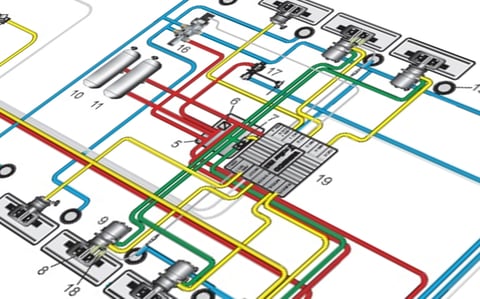
Air Brake System: How It Works on Heavy Commercial Vehicles
When a tractor unit rolls into the workshop, the complaint is not always "the brakes don't hold". More often it is "the brakes hold late". The driver feels a
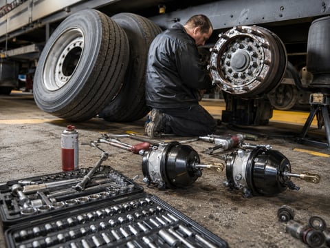
Air Brake Chamber Explained: Types, Sizes, Failure Symptoms & Replacement
Truck and trailer inspection reports rarely say the brake chamber is defective; they report brake force imbalance. Chamber types, sizes, symptoms and replacement.
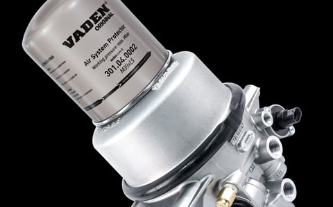
Heavy-Duty Truck Air Dryer: Bendix, WABCO & When to Replace the Cartridge
Almost every question about a truck's air dryer needs one piece of information before it can be answered: which family the dryer on that vehicle belongs to.


