Engine Cylinder Head Group: Faults, Replacement & Maintenance
On a truck diesel a blown gasket, cracked head or coolant mixing into the oil starts here: how the cylinder head group works, diagnosis, replacement and care.
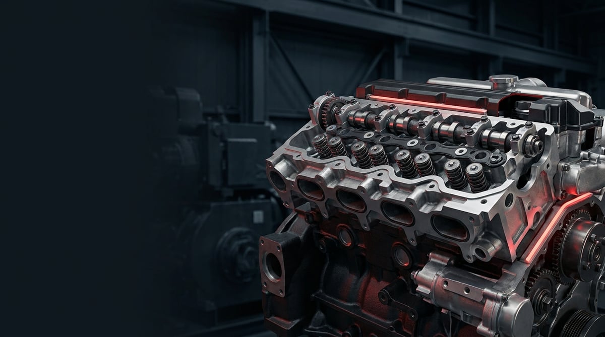
On a heavy commercial vehicle, the cylinder head is the area of the engine that carries the greatest load and is exposed to the highest temperatures and pressures. Most of the problems described in the field as "it's leaking, coolant is mixing in, it blew the gasket" come to a head in this group. A tractor unit stranded on the road or a municipal vehicle out of service often starts here. This guide was prepared to help the field technician recognise the engine cylinder head group, read the symptoms correctly, carry out the replacement by the book and extend its service life.
What Is the Engine Cylinder Head Group? Function and Operating Principle
The engine cylinder head group is the main engine component that closes the top of the cylinder block, sealing the combustion chamber from above, and that carries the valves, valve springs, the rocker/camshaft mechanism and the oil and coolant passages. On heavy commercial vehicles it is manufactured from cast iron or aluminium alloy and forms the most critical region of the engine in terms of pressure, temperature and vibration.
The operating principle, in short, is this: during the piston's compression and combustion strokes the combustion chamber must be fully sealed from the top. The cylinder head closes this chamber from above; the cylinder head gasket keeps the gas, coolant and engine oil passages between the head and the block separate and leak-tight. Through the passages inside the head, coolant circulates to draw off combustion heat while oil galleries lubricate the valve mechanism. The intake and exhaust valves open and close on the seating surfaces (valve seats) on the head, managing charging and exhaust.
Considered as a group, the cylinder head is not a single part but a family of components that work together. The basic components are:
- Cylinder head (body): The main casting that closes the combustion chamber from above; heavy commercial heads of the cylinder-head type may be one piece or separate per cylinder.
- Cylinder head gasket: The multi-layer steel (MLS) or composite gasket that separates gas/coolant/oil between the block and the head.
- Intake and exhaust valves, valve springs, guides and seals: The moving group that manages gas exchange.
- Rocker shaft / rockers and camshaft (in overhead-cam types): The mechanism that transmits the valve opening and closing motion.
- Injector/glow plug bores, heater flange and manifold seating surfaces.
- Valve cover (top cover) and its gasket: The topmost cover that provides oil sealing.
Cast iron or aluminium head?
In heavy commercial diesel engines, cast iron heads have historically been dominant; they offer high resistance to high compression pressure and thermal load, but are heavy. Some new-generation engines use aluminium alloy heads for weight and cooling efficiency. Aluminium heads are more sensitive to thermal expansion and overheating; once they have "run hot", flatness (planarity) can degrade rapidly. Replacement and torque procedures differ between the two materials.
One-piece head or a separate head per cylinder?
Some heavy commercial engines have a one-piece head covering all cylinders, while others have a separate head for each cylinder. The separate-head design allows only the affected head to be removed when a single cylinder fails, providing a great advantage in the field. Part selection and gasket type vary according to this configuration.
OE context and supply
The cylinder head group and the surrounding parts (gasket sets, valve group, thermostat/cooling components) are, on most heavy commercial engines, associated with well-known OE suppliers. Gaskets and sealing elements are generally linked to multi-layer steel technology, the cooling side to Behr/Mahle-equivalent solutions, the fuel/injection side to Bosch-type equipment, and the brake and chassis side to Knorr/Bendix-type systems. VADEN ORIGINAL head group products are positioned to be compatible with this OE context.
| Head / gasket type | Typical use | Key feature |
|---|---|---|
| One-piece cast iron head | Classic heavy commercial diesel (tractor unit, truck) | High thermal resistance, heavy |
| Aluminium alloy head | New-generation, weight-optimised engines | Light, heat-sensitive, precise torque |
| Separate head per cylinder | Modular heavy commercial engines | Individual removal, field convenience |
| MLS (multi-layer steel) gasket | Modern high-pressure diesel | Resistance to repeated clamping |
| Composite / elastomer-coated gasket | Older-generation and mid-segment | Conforms to surface tolerance |
Fault Symptoms and Diagnosis
Cylinder head group faults often begin insidiously: first a slight loss of performance, then coolant loss, and finally a serious leak. The table below sets out the most frequently encountered symptoms in the field, their possible causes and verification methods together.
| Symptom | Possible cause | Check / verification |
|---|---|---|
| Bubbles / gas leak in the expansion tank | Cylinder head gasket breached on the combustion chamber side | Coolant check with an exhaust gas test kit (CO2 test); pressure test |
| Oil in the coolant, water in the oil (brown emulsion) | Gasket leak between oil and coolant passages; crack in the head | Dipstick and filler cap inspection; system pressure test |
| White, sweet-smelling exhaust smoke | Coolant leaking into the combustion chamber | Pressure-drop test; check for wetness in the plug/injector bore |
| Overheating, running hot | Crack in the head or gasket leak; disrupted coolant circulation | Temperature measurement, air-lock check, flatness measurement |
| Uneven running per cylinder, loss of power | Burnt valve, low compression, gasket leak | Per-cylinder compression / leak-down test |
| External oil leak around the head | Valve cover gasket or loss of head clamping torque | Visual leak tracing, torque check, gasket age check |
| Tapping/ticking on cold start, easing when warm | Valve clearance out of adjustment, rocker wear | Valve clearance measurement (feeler gauge), rocker/guide check |
| Continuous coolant loss (no external leak) | Internal gasket leak, head crack | Pressure test + dye/pressure monitoring; eliminating other leak points |
Compression and leak-down test
For per-cylinder power loss, the most reliable method is the compression and leak-down test. The compression test finds the low cylinder; the leak-down test tells you where the leak is going: if air reaches the intake manifold, suspect the intake valve; if it reaches the exhaust, the exhaust valve; if bubbles appear in the expansion tank, a gasket or head crack comes to mind. This distinction is critical for a correct diagnosis before removing the head.
Gasket verification with an exhaust gas (CO2) test
The practical way to determine whether there is combustion gas in the coolant is a colour-changing liquid test kit fitted to the expansion tank. If the liquid changes colour, gas is leaking from the combustion chamber into the cooling system; this almost certainly points to a gasket or head problem. This test, which can be done without dismantling the engine, prevents unnecessary disassembly.
Flatness and crack check
Once the head is removed, the flatness (planarity) of the seating surface is measured with a straight edge and a feeler gauge. If the permitted deviation is exceeded, the head must be resurfaced or replaced. When a crack is suspected, a coloured penetrant (dye) or pressure test is applied; the bridges between the valve seats and injector bores in particular must be examined carefully.
Further reading
For a plain-language technical overview of this subject, see the reference article on Wikipedia. Always confirm specific figures and procedures against the vehicle manufacturer service data.
Replacement / Installation Steps
- Preparation and draining: Cool the engine, disconnect the battery, and drain the coolant and, where necessary, the engine oil into suitable containers. Collect waste fluids in accordance with environmental regulations.
- Removing surrounding components: Remove the intake and exhaust manifolds, turbo connections, injector/fuel lines, glow plug/sensor wiring and coolant hoses, marking as you go. Label every connection.
- Valve cover and mechanism: Remove the valve (rocker) cover. Remove the rocker shaft, push rods and, if present, camshaft connections in sequence, marking them; do not mix up their positions.
- Timing reference: Note the crankshaft and camshaft timing marks. Secure the timing belt/chain or gear as specified by the manufacturer so the timing does not shift during reassembly.
- Loosening the head bolts: Loosen the cylinder head bolts strictly in the sequence specified by the manufacturer (generally outside-to-inside, in stages). Sudden and uneven loosening can warp the head.
- Lifting the head: Lift the head straight up with a lifting device. Do not force it sideways while lifting; the gasket may be stuck, do not pry with a screwdriver (the surface gets damaged).
- Cleaning and measurement: Clean off old gasket residue from the block and head surfaces without scratching the surface. Measure flatness, cracks and valve condition. If necessary, have the head resurfaced or replace it with a new one.
- Seating the new gasket: Fit the new cylinder head gasket of the correct thickness and correct orientation (dry, without applying sealant unless the manufacturer states otherwise). Pay attention to the "TOP/OBEN" mark and the dowel holes.
- Seating the head and NEW bolts: Lower the head, aligning it on the dowels. Stretch-type (torque-to-yield) bolts are single-use; if the manufacturer recommends it, always use new bolts. Lightly lubricate the threads and seating surfaces with the specified oil.
- Staged torque and angle tightening: Tighten the bolts with a torque wrench according to the manufacturer's sequence and stages, first to the pre-torque and then by the angle (degree) method. Never skip the sequence or the stages.
- Assembly, filling and checking: Refit the mechanism, manifolds and lines, adjust the valve clearances, fill the coolant and oil, and bleed the air lock. On first start-up, check for leaks, overheating and noise; some engines require a torque/clearance check after warm-up.
Points to Watch (Common Mistakes)
- Tightening the head bolts by skipping the torque/sequence or with an air wrench; this causes warping and leakage.
- Trying to remove the head on a hot engine; the risk of warping on an aluminium head is high.
- Cleaning off old gasket residue by scratching the surface; every scratch is a new leak path.
- Fitting a new gasket without measuring flatness; a gasket fitted to a warped surface blows within a short time.
- Running the engine without bleeding the air from the cooling system; local overheating and gasket damage.
- Dismantling without noting the timing marks; the risk of valve-to-piston collision.
- Applying sealant needlessly to the gasket surface; it blocks the passages, and a piece of sealant gets into the oil circuit.
Technical Values and Check Points
The values below are typical/general reference ranges for heavy commercial diesel engines; the exact figure varies by engine code and the OE service manual takes precedence. The aim is to give the field technician an order of magnitude and a check point.
| Check point | Typical / general reference range | Note |
|---|---|---|
| Cooling system operating pressure | ~1.0–2.0 bar (~15–29 psi) | Varies with the cap/tank cap pressure |
| Thermostat opening temperature | ~80–90 °C | Differs by engine type |
| Normal operating coolant temperature | ~85–95 °C | Above this range is an overheating warning |
| Cylinder compression pressure (diesel) | Order of ~25–35 bar | The difference between cylinders should not exceed 10% |
| Head flatness tolerance | Order of ~0.03–0.10 mm | If exceeded, resurface/replace; the OE limit is decisive |
| Valve clearance (cold) | Order of intake ~0.2–0.4 mm / exhaust ~0.4–0.6 mm | Only the OE value is used |
Torque values vary greatly according to head type and bolt diameter; the table below is for approximate magnitude only.
| Connection | Typical approximation | Method |
|---|---|---|
| Cylinder head bolt (heavy commercial) | Pre-torque + staged angle (e.g. ~50 Nm pre + 2–3 angle stages) | Sequence + angle method, NEW bolt |
| Rocker shaft / bearing bolt | Order of ~20–45 Nm | In sequence, torque wrench |
| Valve cover bolt | Order of ~8–20 Nm | Over-tightening crushes the gasket |
| Manifold bolts | Order of ~20–40 Nm | Staged from centre outward |
For a quick field check:
- Distinguish internal/external leaks with a cooling system pressure test.
- Verify a gasket leak with a CO2 test in the expansion tank.
- Measure per-cylinder health with a compression/leak-down test.
- Always measure flatness and cracks on the head surface before installation.
- Adjust the valve clearances to the OE value and check them after first start-up.
Maintenance and Service Life
The cylinder head group is not, as a rule, a periodically "replaced" part; on a correctly running engine it is long-lived. However, the real factor that determines its life is the health of the surrounding systems. What finishes off a head early is almost always neglected maintenance.
- Watch the cooling system: Overheating is the number one enemy of head and gasket life. Periodically check the antifreeze/water ratio, the thermostat, the radiator and the water pump.
- Correct antifreeze and clean coolant: Antifreeze of the proper specification prevents corrosion and passage blockage; dirty water blocks passages and creates local overheating.
- Oil and oil change interval: Timely oil changes slow the wear of the valve mechanism and the rockers.
- Valve clearance check: Adjusting the valves at the intervals specified by the manufacturer prevents valve burning and head damage.
- Take early symptoms seriously: A slight coolant loss, the first overheating warning or bubbles in the expansion tank are an opportunity to intervene before it turns into major damage.
- Use quality gaskets and bolts: OE-equivalent gaskets of the correct specification and single-use bolts directly determine how long the repair lasts.
In short, the service life of the cylinder head group depends largely on cooling and lubrication discipline. An operation that keeps heat under control, changes its oil on time and does not ignore the first warning signs will get hundreds of thousands of kilometres out of a head group. A single neglected overheating episode, on the other hand, can crack the head in one go.
The engine cylinder head group is the most critical sealing point at the heart of a heavy commercial vehicle; with correct diagnosis, the right part and installation in accordance with the rules, it runs for a long service life. The VADEN ORIGINAL Engine Cylinder Head Group product family, with its injector sleeves, injector pipes, cylinder head gaskets and plugs, valve bridge and valve adjusting shims, is positioned to meet the OE expectations of heavy commercial vehicles. Make your selection by verifying the part number that matches your vehicle's engine code.
Related categories: Cylinder Head · Injector Sleeve · Injector Pipe · Plug
Related technical guides: Exhaust Manifold: Cracks, Leaks, Replacement & Torque Guide · Exhaust / Engine Brake: Faults, Replacement & Maintenance Guide · Oil Cooler: Failure Symptoms, Replacement & Maintenance Guide · Truck Oil Pan Group: Faults, Replacement & Maintenance Guide · Engine Valve Train & Adjustment Shim: Faults, Replacement, Care
Application and compatibility: Vehicle compatibility catalogue · Engine compatibility catalogue
Main guide: What Is a Crankshaft? Function, Failure Symptoms and Maintenance
Tags
Frequently Asked Questions
- Will the vehicle run when the cylinder head gasket blows?
- It may run for a short time, but running it is risky. Combustion gas can mix into the coolant, and coolant into the combustion chamber or oil; this leads to overheating and permanent engine damage. When the symptom is noticed, the best course is to take the vehicle to a service centre without straining it.
- If the cylinder head cracks, can it be repaired or must it be replaced?
- It depends on the location and size of the crack. Some cracks can be remedied by professional welding/repair; however, for cracks in critical areas such as the combustion chamber and valve bridge, the safe solution is generally to replace the head. The decision should be made after flatness and crack testing.
- Can the cylinder head bolt be reused?
- If the engine uses stretch-type (torque-to-yield) bolts, no; these bolts are single-use and must be renewed. On some older engines a standard bolt can be reused, but this depends entirely on the OE instructions. If you are not sure, fit new bolts.
- Is resurfacing (planing) the head always necessary?
- No. If the head surface is flat within the measured tolerance, resurfacing is not required. Resurfacing is only done when the flatness limit is exceeded and the surface is suitable. Since excessive resurfacing changes the compression ratio, the OE limit must not be exceeded.
- Is the gasket always the cause of oil mixing into the coolant?
- Most of the time it is the gasket or a head crack, but it is not the only cause. A failure of the oil cooler gives similar symptoms too. For a correct diagnosis, a pressure test and leak tracing should clarify whether the source is the gasket, the head or the oil cooler.
- How long does a cylinder head group replacement take?
- It depends on the engine type, the accessibility of the vehicle and additional operations (resurfacing, valve renewal). On a heavy commercial engine this is generally a long and demanding operation; not rushing, and doing the torque and timing by the book, is more important than the job time.
- What does white, sweet-smelling exhaust smoke indicate?
- Continuous white, sweet-smelling smoke from the exhaust is generally a sign that coolant is leaking into the combustion chamber, suggesting a gasket/head problem. It is different from the normal water vapour in cold weather; if it continues after warm-up, it must be checked.
- Is an equivalent (OE-type) cylinder head group safe?
- Quality equivalent parts that match the correct part number and conform to OE specification are widely and safely used in heavy commercial vehicles. What is decisive is material quality, the correct gasket thickness and the correct bolt. VADEN ORIGINAL head group products are manufactured to conform to the OE context.
- What is the difference between a compression test and a leak-down test?
- The compression test finds the low cylinder; the leak-down test tells you where the leak is going. Air reaching the intake manifold points to the intake valve, air at the exhaust to the exhaust valve, and bubbles in the expansion tank to a gasket or a head crack. Making this distinction before removing the head is critical for a correct diagnosis.
- Should sealant be applied to a new cylinder head gasket?
- No, unless the manufacturer states otherwise; the gasket is fitted dry. Needless sealant blocks the coolant and oil passages, and pieces of it end up in the oil circuit. Fit the gasket in the correct thickness and orientation, watching the TOP/OBEN mark and the dowel holes. The OE service manual for the engine takes precedence.
Related Articles

Oil Filter Cap and Housing: Leaks, Cracks and Seal Replacement
Truck engine oil filter cap and housing: why plastic caps crack, O-ring leak causes, bypass valve faults, and correct torque and seal replacement steps.
Piston Rings: Oil Consumption, Compression Loss and Replacement
Ring-related oil consumption and compression loss in truck diesel engines: how rings seal, blow-by and leak-down tests, ring gap and replacement.
Intake Manifold and Intake Pipe: Faults, Diagnosis, Repair
How the intake manifold and charge air pipe work on truck diesel engines, how to spot boost leaks, run a pressure test and fit them leak free.


