Clutch Central Unit (Lower/Upper Servo): Faults & Replacement
Diagnose, replace and maintain the heavy commercial vehicle clutch central unit (clutch booster & master cylinder): symptoms, torque values and field tips.
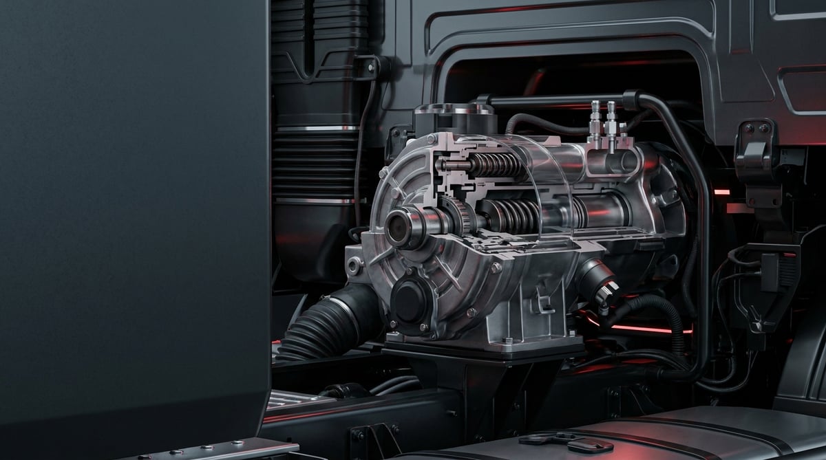
When the clutch on a heavy commercial vehicle turns stiff, the pedal drops away, or gears refuse to engage, the culprit is usually not the clutch itself but the clutch central unit sitting in the middle of the hydraulic-pneumatic chain that operates it. This arrangement, made up of the lower servo (clutch cylinder / clutch booster) and the upper servo (clutch master cylinder), converts the force the driver applies to the pedal into the power needed to disengage the truck's heavy pressure plate. In the field, the majority of "the clutch won't hold", "the pedal stays on the floor", and "it's leaking air" complaints trace back to these two components. This guide brings together the knowledge you need in the field — from identifying the servo type to diagnosing faults, and from removal and installation to service life.
What Is the Clutch Central Unit (Lower/Upper Servo)? Function and Operating Principle
The clutch central unit is the collective name for the arrangement of the upper servo (master cylinder), which converts the force the driver applies to the clutch pedal into hydraulic pressure, and the lower servo (clutch servo / clutch booster), which amplifies this pressure with support drawn from the vehicle's air system and transmits it to the clutch fork.
The operating principle is a force-transmission chain. When the driver presses the pedal, the piston inside the upper servo (master cylinder) pressurizes the hydraulic line (typically DOT-type brake fluid). This hydraulic pressure is carried through the pipe line to the lower servo. The lower servo combines this hydraulic force — which on its own would be insufficient — with compressed air of around 7-9 bar coming from the vehicle's air tank; its large-diameter pneumatic piston multiplies the hydraulic force and pushes the clutch fork (release fork), disengaging the pressure plate from the flywheel. This lets the driver disengage a heavy clutch with a relatively light pedal.
- Upper servo (master cylinder): Converts pedal force into hydraulic pressure; contains the reservoir, piston, and seal set.
- Lower servo (clutch servo / booster): Combines the hydraulic and pneumatic force and delivers it to the fork; houses the hydraulic cylinder, pneumatic cylinder, and control valve.
- Control (relay) valve: Opens/closes the air flow in proportion to the hydraulic signal.
- Push-rod and fork linkage: Carries the force to the clutch release bearing.
- Seal, o-ring, and sleeve kit: Provides sealing on both the hydraulic and pneumatic sides.
The Division of Labor Between the Upper Servo (Master Cylinder) and the Lower Servo
The upper servo can be thought of as a "signal generator": it initiates the force and determines the pedal feel. The lower servo is the "power amplifier"; it does the real heavy lifting with air support. That is why a softening pedal usually points to the upper servo, while incomplete clutch disengagement or an air-leak sound usually points to the lower servo. Because the two parts work interdependently, when replacing one, the condition of the other and of the connecting line must always be checked as well.
Hydraulic-Pneumatic (Combined) System or Fully Hydraulic?
Most heavy commercial vehicles use a combined (hydraulically commanded, air-assisted) lower servo, because the clutch force is too high to be met by hydraulics alone. On some mid-segment and older-generation vehicles, a fully hydraulic or direct mechanical linkage may be seen. The servo type is the first determinant of the correct spare-part choice.
Type and Application Comparison
| Feature / Type | Upper Servo (Master Cylinder) | Lower Servo (Clutch Booster) |
|---|---|---|
| Main function | Convert pedal force into hydraulic pressure | Combine hydraulic + air force and deliver it to the fork |
| Operating medium | Hydraulic (brake fluid) | Hydraulic + pneumatic (7-9 bar air) |
| Typical fault | Internal leak, pedal fade, drop in hydraulic level | Air leak, incomplete disengagement, external hydraulic leak |
| Mounting location | Near the pedal assembly, under the cab | Beside the transmission / clutch housing |
| Aftermarket brand context | Knorr-Bremse type, Wabco type | Knorr-Bremse type, Wabco type, Bendix type |
Fault Symptoms and Diagnosis
Clutch central unit faults usually develop gradually: first the pedal feel changes, then gear shifts become harder. The table below matches field complaints with likely causes and verification methods.
| Symptom | Likely Cause | Check / Verification |
|---|---|---|
| Pedal softened, sinks to the floor and returns slowly | Upper servo internal seal leak, low hydraulic level | Check the hydraulic reservoir level and pedal free play; if pumping the pedal firms it up, there is air/a leak |
| Gears shift hard, the clutch does not fully disengage | Lower servo stroke insufficient, low air support | Observe fork movement and air pressure with the engine running; measure the fork stroke and compare it against the OE value |
| Hissing / air-leak sound when the clutch is pressed | Lower servo control valve or sleeve leak | Check the valve and body connections with soapy foam; if the leak grows when the pedal is pressed, the valve is faulty |
| Hydraulic leak from the servo body | Worn o-ring / seal, cracked body | Wipe dry and press again; dampness around the push-rod indicates a seal leak |
| Clutch stiffens when air pressure drops | Lower servo air support disabled, valve blockage | Check the tank pressure and servo supply line with a gauge; the line may be restricted |
| Pedal stiffened, harder to press | No air support / valve locked, push-rod binding | Check the air supply line and valve freedom; inspect the mechanical friction points |
| Juddering on take-off and clutch shudder | Irregular servo stroke, fork play, air-hydraulic imbalance | Measure the free movement of the fork at idle; compare stroke and play values against the OE range |
Tackle the Simple Things First: Level and Play
Before embarking on a complex diagnosis, check the hydraulic level, the pedal free play, and the air tank pressure. In a significant share of cases the problem stems from a low hydraulic level, misadjusted pedal play, or insufficient air pressure; it can be resolved without replacing the servo.
Internal Leak or External Leak?
An external leak is visible: there is dampness, dripping, or an air sound on the body. An internal leak is insidious; the pedal fades slowly with no visible leak outside, because the hydraulic fluid escapes back through the seal. A pedal that slowly sinks while held down typically points to an internal leak in the upper servo.
Assess the System as a Whole
If the clutch is not working, before blaming the servo directly, also assess the release bearing, the fork, the pressure plate / clutch disc, and the hydraulic line. Even with a healthy servo, a bent fork or a binding bearing can produce the same symptom. Correct diagnosis is only possible by following the chain from end to end.
Further reading
For a plain-language technical overview of this subject, see the reference article on Wikipedia. Always confirm specific figures and procedures against the vehicle manufacturer service data.
Replacement / Installation Steps
- Preparation and diagnosis confirmation: Confirm that the fault really is in the servo using the methods in the diagnosis section; avoid unnecessary disassembly.
- Make the system safe: Switch off the ignition, bleed off the air pressure, consider disconnecting the battery, and clean the work area.
- Drain the hydraulic fluid: Drain the hydraulic fluid from the upper servo reservoir into a suitable container; prevent the fluid from being spilled onto the ground/into drains.
- Disconnect the air line: Mark and disconnect the lower servo's supply air line; protect the fittings and unions against contamination.
- Separate the hydraulic pipe: Disconnect the hydraulic inlet/outlet pipes; contain dripping fluid with a cloth and plug the lines.
- Undo the mechanical linkage: Disconnect the push-rod and fork linkage; note the adjustment dimension (stroke/play).
- Remove the old servo: Progressively loosen the mounting bolts and take the servo out; clean the mounting face and threads.
- Check the new servo: Compare the number, piston diameter, stroke, and connection geometry of the VADEN aftermarket part against the old part.
- Install the new servo: Seat the servo in place, tighten the bolts to the manufacturer's specified torque in a cross pattern; check the fork alignment.
- Connect the lines and bleed: Connect the hydraulic and air lines, fill the reservoir with suitable fluid, and fully bleed the air from the system.
- Adjust and test: Set the pedal free play and fork stroke to the OE value; with the engine running, verify gear shifts and the absence of leaks.
Points to Watch (Common Mistakes)
- Dirty installation: Letting dust/dirt into the hydraulic and pneumatic lines shortens valve and seal life; keep the connections clean.
- Replacing only one part: When replacing a worn lower servo, leaving in an upper servo or line whose health you are not sure of brings the problem back quickly.
- Neglecting torque: Tightening bolts by guesswork leads to a cracked body or a leak; always use a torque wrench.
- Skipping the fork and bearing check: A bent fork or a binding bearing will soon strain the new servo too.
- Not verifying the air supply pressure: A test done with low tank pressure makes even a healthy servo look "weak".
Technical Values and Check Points
The values below are typical/general reference ranges for heavy commercial vehicles; they vary by vehicle, transmission, and servo type. For the exact value, the vehicle's service manual must always be taken as the basis.
| Parameter | Typical / General Reference Range | Note |
|---|---|---|
| Air system supply pressure | ~7-9 bar (≈100-130 psi) | Lower servo air support works in this range; if low, disengagement weakens |
| Hydraulic line working pressure | ~30-60 bar (higher at peak) | Varies with pedal force and piston diameter |
| Fork / push-rod stroke | ~25-45 mm | Must be set to the OE value; if the stroke is insufficient it won't fully disengage |
| Pedal free play | ~5-15 mm | Without play, the bearing is under constant load |
| Operating temperature range | ~ -40 °C to around +80 °C | The seals and fluid must be selected for this range |
| Air leak tolerance | No leak should be visible under pressure by eye/foam | Pressure drop is monitored in a static test |
Typical torque ranges for the mounting bolts are given below. These are general references; bolt diameter, class, and the OE instruction take priority.
| Connection | Typical Torque Range | Note |
|---|---|---|
| Servo body mounting bolts (M10) | ~40-55 Nm | Tighten in a cross pattern, progressively |
| Servo body mounting bolts (M12) | ~70-95 Nm | The OE value is taken as the basis |
| Hydraulic pipe union | ~15-25 Nm | Over-tightening damages the thread/cone |
| Air line fitting | ~20-35 Nm | The sealing gasket is checked |
- Verify the air tank pressure with a gauge; make sure there is no restriction in the supply line.
- Check with soapy foam that the servo does not leak either statically or with the pedal pressed.
- Measure the fork stroke and pedal free play and set them to the OE value.
- After bleeding the air, check and top up the hydraulic level again.
- In the first kilometers, re-inspect the connection torques and any possible leak.
Maintenance and Service Life
The clutch central unit is an assembly that works long and reliably with proper maintenance but fails suddenly when neglected. The main factors determining its life are hydraulic fluid quality, the cleanliness of the air system, and regular adjustment checks. Moisture and oil in the system air rapidly wear the valves and seals; that is why the air dryer and tank draining must not be neglected.
- Hydraulic check: The level and color should be monitored regularly; darkened/contaminated fluid should be renewed at the manufacturer's recommended interval.
- Air system maintenance: The air dryer cartridge and tank draining should be done regularly; the system should be kept dry against moisture.
- Adjustment tracking: Pedal play and fork stroke should be measured periodically and kept at the OE value.
- Leak observation: The area around the servo should be checked regularly for hydraulic and air leaks.
- Connections and torque: Connections that can loosen from vibration should be checked during servicing.
A well-maintained clutch servo serves trouble-free for many years; most early failures stem from dirty air, the wrong fluid, or a skipped adjustment. Regular checks protect both the part and the release bearing and pressure-plate/disc assembly connected to it.
If you have identified a fault in your clutch central unit, choosing the right servo is the first condition of service life and safety. The VADEN ORIGINAL Clutch Central Unit (Lower/Upper Servo) product family is manufactured with the correct piston diameter, stroke, and connection geometry for the hydraulic-pneumatic clutch systems of heavy commercial vehicles; by matching it to your vehicle's OE reference, you can select the right servo and achieve long-lasting, safe clutch performance.
Related categories: Clutch Servo · Master Cylinder · Repair Kit
Related technical guides: Clutch Fork: Fault, Replacement and Maintenance Guide · Clutch Hose Failure, Replacement and Maintenance Guide · Hydraulic Clutch Pedal Unit: Fault Diagnosis, Replacement, Maintenance · Clutch Release Bearing: Fault, Replacement and Care Guide
Application and compatibility: Vehicle compatibility catalogue · Engine compatibility catalogue
Main guide: Clutch Master and Slave Cylinder Failure Symptoms
Tags
Frequently Asked Questions
- How do I tell whether the lower or the upper clutch servo is faulty?
- A pedal that slowly fades and softens along with a dropping hydraulic level usually points to the upper servo (master cylinder). An air-leak sound when the clutch is pressed, incomplete clutch disengagement, and stiffening tied to air pressure point to the lower servo (booster). For a definite distinction, the hydraulic level, fork stroke, and air pressure should be checked together.
- The clutch has stiffened — does the servo have to be replaced?
- Not always. A common cause of stiffening is low air pressure, a blocked supply line, or a locked control valve. First check the air pressure and the line; if the problem is not in these, servo replacement comes onto the agenda.
- The clutch pedal sinks to the floor and doesn't return — what's the reason?
- The most common cause is an internal leak in the upper servo and a drop in the hydraulic level. Air remaining in the system gives a similar symptom too. Check the hydraulic level and bleed the air from the system; if the pedal does not recover, an internal leak in the upper servo is likely.
- I fitted a new servo but the gears still shift hard — why?
- The most frequent cause is that the air was not fully bled; air remaining in the system prevents the clutch from fully disengaging. In addition, the fork stroke/pedal play may be misadjusted, or the release bearing and pressure plate/disc may be worn. Bleed the air fully, make the adjustment, and check the clutch assembly.
- Is an air leak in the clutch servo dangerous?
- An air leak both reduces clutch performance and can strain the vehicle's air system, affecting other pneumatic functions including the brakes. If a leak is detected it must not be neglected; the valve/seal should be checked and the servo renewed if necessary.
- How long does a clutch servo last?
- It would not be right to give an exact mileage; the life depends on operating conditions, air-system cleanliness, and maintenance discipline. With dry, clean air, the right fluid, and regular adjustment, servos last for many years; when neglected, early failure appears.
- Can an aftermarket clutch servo be used in place of the OE part?
- As long as the part number, piston diameter, stroke, and connection geometry match, quality aftermarket servos can be used safely in place of the OE part. What matters is matching with the correct reference; visual similarity alone is not enough.
- Which fluid should I use when replacing the servo?
- The fluid type specified by the vehicle manufacturer should be used (a specific DOT class in most systems). The wrong fluid ruins the seals and causes leaks; avoid mixing types and take the service manual as the basis.
- Why does the lower servo need air assistance — isn't hydraulic pressure enough on its own?
- The force needed to release a truck's heavy pressure plate from the flywheel is too high for hydraulics alone. The upper servo pressurizes the line and the lower servo combines that force with compressed air of around 7-9 bar from the vehicle's air tank; its large-diameter pneumatic piston multiplies the force and pushes the release fork. That is how a driver disengages a heavy clutch with a relatively light pedal. Fully hydraulic or direct mechanical linkages are mainly found on mid-segment and older-generation vehicles.
- How do I verify that the installation is sound after fitting a new servo?
- With the engine at idle, press the clutch a few times and watch the fork: a clear stroke, a fast return and no leak mean the installation is sound. Then check the servo with soapy foam both statically and with the pedal pressed, verify the air tank pressure with a gauge, set the fork stroke and pedal free play to the OE value, and top up the fluid level after bleeding. Re-inspect the connection torques over the first kilometers.
Related Articles

Hydraulic Clutch Pedal Unit: Fault Diagnosis, Replacement, Maintenance
How to diagnose a faulty hydraulic clutch pedal unit on trucks, replace and properly bleed it, and maintain it to prevent a spongy clutch pedal.
Clutch Release Bearing: Fault, Replacement and Care Guide
How a truck clutch release bearing works, how to spot noise and pedal symptoms, measure release travel, replace it correctly and extend its life.
Clutch Hose Failure, Replacement and Maintenance Guide | VADEN
Clutch hose symptoms, swelling test, step-by-step replacement, torque values and maintenance tips for heavy commercial vehicles — VADEN technical guide.


