Compressor Piston-Ring & Connecting Rod: Repair Guide
Diagnose, replace and maintain the heavy truck compressor piston, rings and connecting rod. VADEN technical guide: symptoms, torque, clearances and fixes.
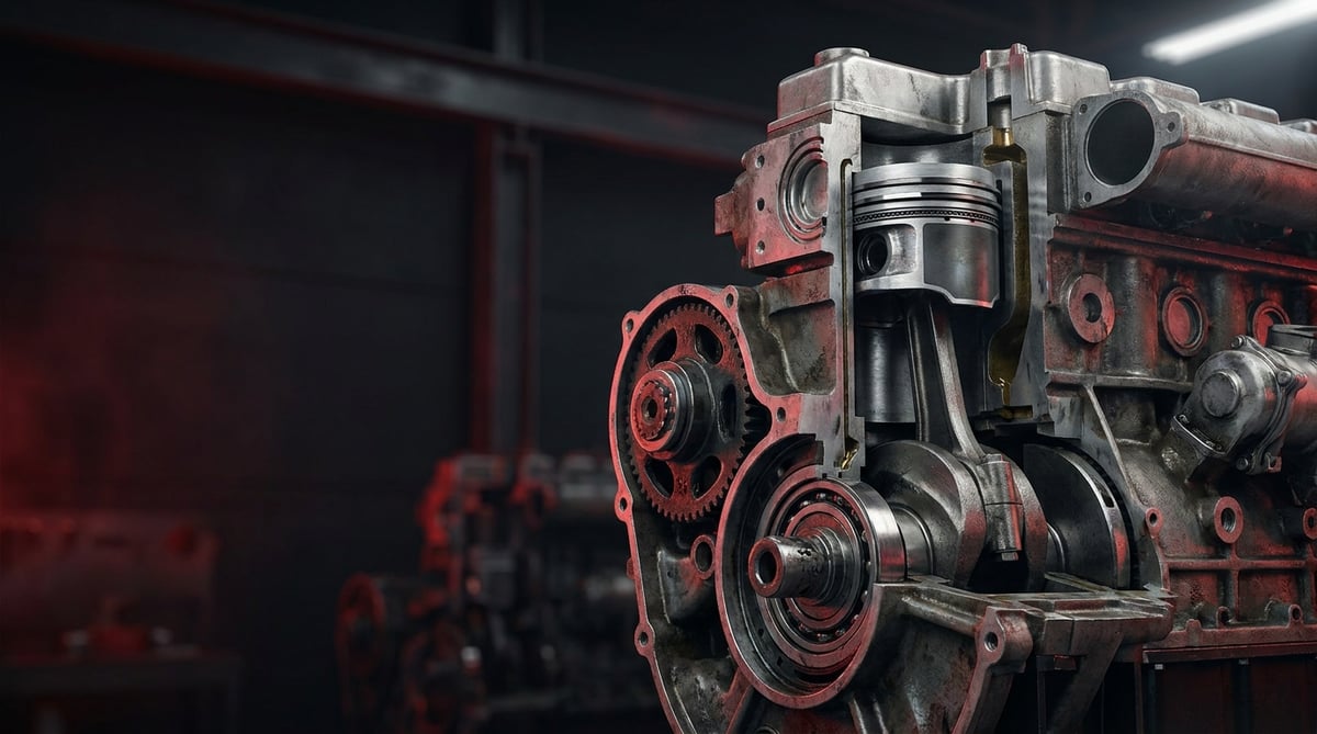
When air pressure drops on a heavy commercial vehicle, oil leaks from the compressor outlet, and oil keeps coming through the air dryer, the root cause usually traces back to the compressor's rotating assembly — the piston, rings, and connecting rod. Much of what technicians describe in the field as "the compressor is throwing oil" is in fact wear, an opened ring end gap, or connecting rod bearing clearance in this group. Combining the field experience of the VADEN technical team with OE service logic, this guide explains what this rotating assembly does, how it fails, and the correct steps for diagnosis, replacement, and maintenance.
What Is the Compressor Piston-Ring & Connecting Rod (rotating assembly)? Function and Operating Principle
The compressor piston-ring & connecting rod rotating assembly is the moving group that brings together the piston which compresses air inside the cylinder, the ring set that keeps the cylinder wall sealed, and the connecting rod that transmits crank motion to the piston — the group directly responsible for the compressor's pressure generation and oil sealing.
The operating principle rests on the same fundamentals as the engine itself: as the crankshaft rotates, the connecting rod moves the piston up and down inside the cylinder. As the piston travels down, air is drawn in through the intake valve; as it travels up, this air is compressed and delivered through the discharge valve to the air system (dryer and reservoirs). The rings perform two critical tasks simultaneously: they prevent the compressed air from escaping to the crankcase side (compression sealing) and they scrape the oil film coming from the crank side to limit oil passage into the compression chamber (oil control). A breakdown of this balance is the root cause of most compressor problems.
- Piston: Usually aluminum alloy or cast iron; carries the ring grooves and the piston pin bore.
- Compression ring: The upper ring(s) that hold pressure; resistant to heat and pressure.
- Oil scraper ring: Scrapes excess oil off the cylinder wall; determines oil consumption and carbon buildup.
- Connecting rod: The small end connects to the piston pin, the big end to the crank journal; converts rotary motion into linear motion.
- Connecting rod bearings / bushings: Big end is a plain (capped) bearing, or a roller bearing depending on the type; small end bushing.
- Piston pin and retaining rings (circlips): Connect the piston to the connecting rod.
Rotating assembly differences between single- and twin-piston compressors
Depending on air demand, heavy commercial vehicles use single-cylinder or twin-cylinder (tandem) compressors. Twin-cylinder types have two separate piston-ring groups and usually two connecting rods; this delivers higher air flow but makes balance, ring orientation, and cap numbering more critical during rotating assembly replacement. When ordering the assembly, the number of cylinders and the bore-stroke combination must always be verified.
Plain bearing or roller-bearing connecting rod?
On some heavy vehicle compressors, the connecting rod big end is a plain (bearing, capped) design and is lubricated with pressurized oil from the engine. Other types use a roller-bearing connecting rod. This distinction changes both the spare part selection and the assembly/torque procedure; choosing the wrong type leads to early failure.
Relationship with lubrication and cooling type
The compressor mostly takes its oil from the engine lubrication circuit (pressure lubrication) and is cooled by a water jacket or by air. The life of the rotating assembly depends directly on the cleanliness and pressure of the incoming oil and the adequacy of cooling. That is why a rotating assembly failure is often not a "part defect" but a consequence of the supply conditions.
| Compressor type / application | Typical rotating assembly structure | Point to watch |
|---|---|---|
| Single-cylinder, medium-tonnage tractor/truck | Single piston + connecting rod, plain big end | Oil feed hole and cap orientation |
| Twin-cylinder (tandem), heavy tractor | Twin piston-ring, two connecting rods | Balance, cap numbering, ring gap orientation |
| Water-cooled heavy vehicle compressor | Cast piston, multi-ring | Cylinder/water jacket gasket integrity |
| Air-cooled light-medium commercial | Aluminum piston, thin ring | Overheating and ring sticking |
Failure Symptoms and Diagnosis
Rotating assembly failures usually develop gradually: first the air build-up time lengthens, then oil consumption and leakage begin, and in advanced stages mechanical noise and total pressure loss appear. The table below presents the symptoms most frequently encountered in the field along with their likely causes and verification methods.
| Symptom | Likely Cause | Check / Verification |
|---|---|---|
| Oil coming from the air dryer/outlet, oily air in the system | Oil scraper ring wear, ring sticking, loss of cylinder glaze | Check dryer inlet and reservoirs for oil; observe oil film on the outlet line |
| Pressure rises slowly, compressor runs continuously | Worn/broken compression ring, cylinder wear, valve leakage | Measure pressure build-up time; valve must be ruled out separately |
| Knocking/rattling noise from the compressor (increasing with speed) | Connecting rod big end bearing clearance, pin clearance, loose circlip | Compare idle vs. under-load noise; measure bearing clearance during teardown |
| Excessive pressure/smoke from crankcase ventilation (blow-by) | Ring leakage, increased cylinder-piston clearance | Observe blow-by from the crankcase plug; measure cylinder bore |
| Excessive oil consumption, rapid drop in engine oil level | Compressor pushing oil that does not return, or ring leakage | Check oil return line and ring condition; color/smell check |
| Compressor overheating, carbon/scorching at the outlet | Insufficient cooling, excess oil + high duty cycle | Check outlet temperature and water/air cooling; observe carbon buildup |
| Air pressure never builds, compressor runs unloaded | Broken ring, seizure, connecting rod/piston damage | Disassemble to check mechanical damage; feel compression by hand |
Oil leak or valve problem? How to tell them apart
A significant portion of the oil and pressure problems on a compressor actually originate from the intake/discharge valves. Before touching the rotating assembly, the valve plate and reed valves must be checked; a judgment on the rings and piston should only be made after the valves have proven sound. Otherwise a healthy rotating assembly is disassembled unnecessarily.
Noise diagnosis: connecting rod or pin?
Connecting rod big end clearance usually produces a deep, rhythmic knock under load, whereas piston pin clearance produces a more metallic, double-strike ("ringing") sound. A definitive distinction is only made by measuring clearance during teardown, but the character of the sound indicates which area to prioritize.
Reading blow-by and crankcase pressure
As ring leakage grows, the compressed air seeps to the crankcase side (blow-by). Strong, continuous pressure and oily vapor felt at the crankcase ventilation opening is a strong sign that the ring/cylinder group has reached the end of its life. This finding should not be evaluated alone but together with the pressure build-up time and oil consumption.
Standards and further reading
This subject is governed by the equipment rules for air-braked commercial vehicles. In the United States the federal air brake standard, FMVSS 121 (49 CFR 571.121) defines the reservoirs, protection and timing a compliant system must provide, and Europe applies the equivalent limits of UNECE Regulation No. 13. For further detail, see the illustrated reference guide at airbrakecompressor.com. Always confirm specific figures against the current regulation and the vehicle manufacturer service data.
Readers outside the United States should work from their own national framework: in the United Kingdom the braking system must be maintained under regulation 18 of the Road Vehicles (Construction and Use) Regulations 1986, and in India the governing rules are published by the Ministry of Road Transport and Highways.
Replacement / Installation Steps
- Secure the system: Discharge the air pressure, disconnect the battery, wait for the compressor to cool, and clean the work area.
- Disconnect the connections after marking them: Separate the air inlet/outlet lines, oil feed and return pipes, and water cooling hoses (if any) with numbering; plug the openings to prevent contamination.
- Remove the compressor (if necessary): For full access to the rotating assembly, remove the compressor from the vehicle and place it on a clean bench; be careful on the coupling/gear side.
- Remove the cylinder head and valve plate: Loosen the bolts in a crosswise sequence; set aside the gasket and valve plate for assessment.
- Open the crankcase cover and gain crank access: Reach the connecting rod caps; always note the cap and body marks (the caps must not be mixed up).
- Remove the connecting rod: Loosen the cap bolts, take off the big end bearing/cap, and push the rod-piston group up out of the cylinder; do not scratch the wall with ring debris.
- Separate the piston and rings: Remove the circlips, take out the pin; remove the old rings with ring pliers. Inspect the cylinder and piston surfaces.
- Measure and decide: Measure the cylinder bore, ovality, piston diameter-clearance, and connecting rod bearing clearance; if out of limits, replace the rotating assembly completely, and if the cylinder is worn, evaluate the body/cylinder.
- Fit the new rings: Check the ring end gap, install the rings by staggering the gaps at the angle specified by the manufacturer (without overlapping them); pay attention to the oil scraper orientation.
- Install the piston and slide it into the cylinder: Fit the piston pin and seat new circlips, compress the rings with a piston ring compressor, and lower the piston into the cylinder without damage; follow the assembly orientation mark.
- Connect, torque, and check the connecting rod: Fit the cap in the correct orientation and tighten the bolts progressively with the torque and sequence in the service manual; turn the crank by hand to check for seizure/free movement. Then install the valve plate, gasket, and covers with new gaskets and torque them.
Things to Watch (Common Mistakes)
- Do not reuse old valves, gaskets, and circlips; the sealing elements must be renewed when the rotating assembly is replaced.
- Replacing only the rings while the cylinder is worn or oval is not a permanent solution; the leak returns in a short time.
- Do not neglect lubrication during assembly; installing the rings and cylinder dry causes scoring and seizure on first start.
- Do not install without cleaning the oil feed and return line; a dirty supply will destroy even a new rotating assembly quickly.
- Replacing the ring because the compressor was throwing oil while skipping the real cause (blocked oil return, excessive crankcase pressure, valve leakage) is a common mistake.
- Do not ignore the piston orientation mark (arrow/notch) and the ring "TOP" mark.
Technical Values and Check Points
The values below are typical / general reference ranges for heavy commercial vehicle compressors; the exact operating pressure, clearance, and torque values vary by compressor type and vehicle manufacturer. The OE service manual must always be the basis for the final value.
| Parameter | Typical reference range | Note |
|---|---|---|
| System cut-out pressure (governor) | ~10–13 bar (≈145–190 psi) | Varies with the vehicle air system |
| Compressor outlet (discharge) temperature | Usually < 200–220 °C momentary peak | Continuous overheating causes carbon buildup |
| Ring end gap | ~0.20–0.50 mm (typical) | Taken from the manual per cylinder bore |
| Piston-cylinder clearance | Order of ~0.03–0.10 mm | Blow-by increases as it wears |
| Connecting rod big end bearing clearance | Order of tenths-hundredths mm (per manual) | Main source of the knocking noise |
| Oil feed pressure (from engine) | Consistent with engine oil pressure | Low pressure causes early wear |
Torque values also vary by type; the table below is only a reference showing the order of magnitude — the actual value must be taken from the manual.
| Connection | Typical torque range (reference) | Application note |
|---|---|---|
| Connecting rod cap bolt | ~20–45 Nm + angle (by type) | Sequence and stage per manual; new bolt if required |
| Cylinder head bolts | Order of ~20–40 Nm | Crosswise and staged tightening |
| Valve plate / head bolts | Staged per manual | Sequence matters for gasket seating |
- Check for loss of glaze (honing marks) and oval wear on the cylinder wall.
- Check the ring grooves for carbon/sticking and check the free movement of the rings.
- Verify that the oil return hole is open and clean.
- Turn the crank by hand to confirm equal resistance (no seizure) throughout each revolution.
- On first start, observe oil leakage, noise, and pressure build-up time.
Maintenance and Service Life
The service life of the compressor rotating assembly depends largely on operating conditions rather than the part itself. With clean oil at the correct pressure, adequate cooling, and a reasonable duty cycle, the rotating assembly runs trouble-free for a long time; with dirty oil, a blocked return line, and constant full load, it wears out quickly.
- Change the engine oil and filter on time: Since the compressor takes its oil from the engine, oil quality directly determines rotating assembly life.
- Replace the air dryer cartridge periodically: A saturated dryer causes moisture and oil to accumulate in the system and creates back pressure.
- Check the oil return and feed lines: A blockage causes oil to accumulate in the crankcase and strains the rings.
- Fix leaks early: Continuous leakage raises the compressor's duty cycle; a continuously running compressor both heats up and wears out quickly.
- Monitor outlet temperature and carbon buildup: Overheating is a precursor to ring sticking and oil scorching.
- Periodically drain water/oil from the reservoirs: Accumulated condensate is an early indicator of system health.
After the rotating assembly is renewed, the pressure build-up time, oil consumption, and dryer outlet should be monitored closely in the first miles; when early warning signs (oily air, lengthening build-up time) are caught, major failure and being stranded on the road can be prevented. The trio of the right part, correct assembly, and regular maintenance is the cheapest way to protect the rotating assembly, the most expensive group of the compressor.
A quality rotating assembly produced with the correct bore-stroke, pin dimension, and bearing structure suited to your vehicle's compressor type provides a safe and long-lasting solution in the most critical group of the compressor. The VADEN ORIGINAL Compressor Piston-Ring & Connecting Rod (rotating assembly) product family is offered with a dimension and material approach in line with OE logic for heavy commercial vehicle compressors; you can review our product family to verify the reference suited to your vehicle and choose the correct rotating assembly.
Related categories: Piston & Ring · Piston · Ring · Cylinder Liner Set · Cylinder Liner · Connecting Rod & Piston
Related technical guides: Truck Air Compressor Overhaul Kit: Head, Valve Plate, Gasket · Compressor Crankshaft & Drive Assembly: Failure & Replacement Guide · Compressor Valve & Unloader: Fault, Replacement & Care Guide · Compressor Cooling Plate & Water Cooling: Faults, Repair & Care
Application and compatibility: Vehicle compatibility catalogue · Engine compatibility catalogue
Main guide: Air Brake Compressor: Faults, Replacement & Maintenance Guide
Tags
Frequently Asked Questions
- The compressor keeps throwing oil — is replacing only the rings enough?
- Often it is not. Oil throwing is caused, besides ring wear, by a blocked oil return line, a worn cylinder, or valve leakage. If the cylinder is oval or the return line is blocked, even new rings start throwing oil in a short time. The root cause must be confirmed first, and if necessary the rotating assembly should be replaced completely.
- Should I buy the complete rotating assembly or piece by piece?
- On heavy commercial vehicles it is generally recommended to renew the piston, rings, pin, and connecting rod bearings together (as a rotating assembly/repair set); replacing one part and leaving the others old causes uneven wear and early failure. If the cylinder is also out of limits, the body/cylinder must be evaluated separately.
- Why is the piston ring end gap important?
- The ring expands when it heats up; if the end gap is too small, the ring seizes and breaks in the cylinder, and if it is too large, it leaks pressure. That is why, during assembly, the end gap must be checked against the manual value and the gaps must be distributed without overlapping.
- There is a knocking noise from the compressor — is the connecting rod faulty?
- A rhythmic knock that increases with speed and becomes prominent under load usually points to connecting rod big end clearance; a more metallic double-strike may be piston pin clearance. A definitive distinction is made by disassembling and measuring clearance. If there is noise, the compressor should be taken to service before it is strained.
- I fitted a new rotating assembly — what should I watch for on first start?
- Watch oil leakage, abnormal noise, and pressure build-up time; confirm during assembly that the crank turns freely by hand. In the first miles, check whether there is oil at the dryer outlet and check the engine oil level. An early sign lets you catch an assembly error before it turns into a major failure.
- Does an aftermarket rotating assembly last as long as OE?
- A quality aftermarket rotating assembly produced to the correct dimensions, material, and tolerances gives long life with assembly and maintenance in line with OE logic. The determining factor is that the part fits the compressor type exactly (diameter, pin, ring section, bearing type) and that assembly is done per the manual. Incorrect dimensions or poor material cause early failure regardless of the brand.
- Why does the compressor overheat and how does it affect the rotating assembly?
- A high duty cycle (continuous operation), insufficient cooling, or excess oil raises the outlet temperature. Excessive heat scorches the oil, builds carbon in the ring grooves, and sticks the rings; the result is again oil throwing and pressure loss. Fixing leaks and ensuring cooling protects the rotating assembly.
- How often is a check/renewal needed?
- Instead of a fixed mileage, look at the symptoms: oily air, lengthening build-up time, increasing oil consumption, and blow-by. When these signs appear, it is time for a check. On vehicles with regular oil/filter and dryer maintenance, the rotating assembly gives much longer life.
- Why does replacing the rotating assembly need more care on a twin-cylinder (tandem) compressor?
- Twin-cylinder types have two separate piston-ring groups and usually two connecting rods. Air flow is higher, but balance, ring orientation and cap numbering become more critical; each cap must go back on its own body in the marked orientation. When ordering, always verify the number of cylinders and the bore-stroke combination, because assemblies that look alike outside are not interchangeable.
- What does strong pressure and oily vapor at the crankcase breather tell me?
- That is blow-by: as ring leakage grows, compressed air seeps to the crankcase side. Continuous pressure and oily vapor felt at the ventilation opening is a strong sign that the ring/cylinder group has reached the end of its life. Do not judge on that finding alone; read it together with pressure build-up time and oil consumption, and check the valve plate first.
Related Articles
Compressor Connection Hardware: Faults, Replacement, Care
How truck air compressor adapters, bolts, plugs and hoses fail, how to diagnose leaks and blockages, replace them correctly and extend service life.
Compressor Repair and Gasket Kit: Faults, Replacement, Care
Diagnosing air compressor gasket failure on trucks: choosing the right repair kit scope, preparing surfaces, torquing correctly and extending seal life.
Compressor Cooling Plate & Water Cooling: Faults, Repair & Care
Diagnose, replace and maintain the heavy-truck air compressor cooling plate and water cooling: symptoms, internal-leak testing, torque values and FAQ.


