Foot Brake Valve: Faults, Replacement & Maintenance Guide
Pedal free play or unbalanced braking on a heavy truck often traces to the dual-circuit foot brake valve: fault diagnosis, gauge testing and replacement.
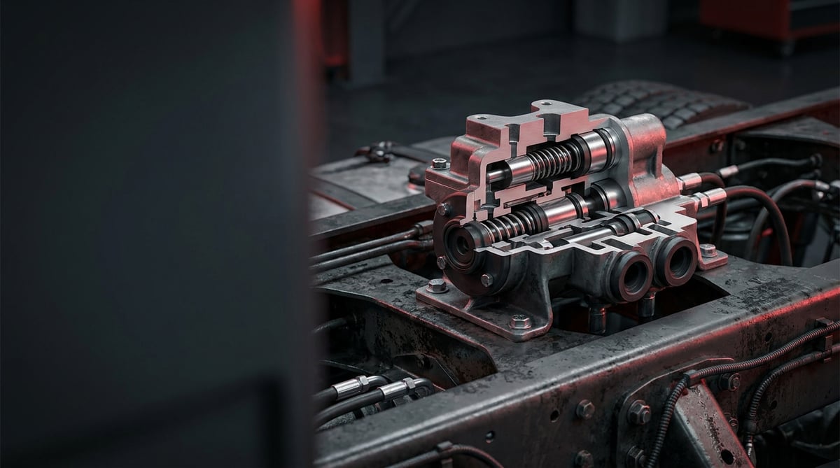
On a heavy commercial vehicle, the component that determines what happens the instant the brake is applied is the brake pedal valve, right under the driver's foot. In the field it goes by "foot brake valve", "dual-circuit brake valve", or simply "pedal valve". In truck, tractor unit and bus fleets, complaints such as pedal free play, delayed brake response, or a single axle locking harshly frequently trace back to this valve. Drawing on the field experience of the VADEN technical team, this guide brings the valve's function, failure symptoms, correct diagnostic method, replacement steps and service life together in one place.
What Is a Brake Pedal Valve (Foot Brake Valve)? Function and Operating Principle
The brake pedal valve is a dual-circuit pneumatic control valve that converts the force the driver applies to the pedal into a proportional air pressure, feeding the front and rear brake circuits independently but simultaneously on a heavy commercial vehicle.
In modern trucks and buses, the brake system is split into two separate air circuits for safety: typically one for the front axle(s), and the other for the rear axle(s) and the trailer/semi-trailer control. The foot brake valve manages both circuits in a single body. When the driver presses the pedal, the valve directs the supply pressure coming from the air tanks to the brake chambers (diaphragm type at the front, usually spring brake actuators at the rear) in proportion to the pedal force. When the pedal is released, the valve rapidly exhausts the chamber air to atmosphere, releasing the brakes.
At the heart of the valve is a "graduable control" logic: the harder the pedal is pressed, the higher the output pressure, approaching the supply pressure at full application. This lets the driver modulate braking intensity progressively. If one of the two circuits fails and loses pressure, the valve is designed to keep feeding the other circuit mechanically; this is the system's dual-safety (fail-safe) feature.
- Upper and lower piston/relay group: Provides the proportional control of both circuits.
- Balance (equalizing) springs: Proportion the pedal force to the output pressure, defining the "feel".
- Inlet and exhaust valves: Open and close the supply and exhaust passages.
- Body and O-ring/seal set: Separates the two circuits without leakage.
- Pedal/plunger (pusher) and dust boot: Force transfer and protection against contamination.
- Silenced exhaust port: Vents the air when the brakes are released.
Floor-Mounted vs. Console-Type Difference
Foot brake valves fall into two main groups according to their in-cab mounting arrangement: the "floor-mounted type" where the pedal sits directly on the valve, and the "suspended/console type" where the pedal is separate and triggers the valve through a plunger/pusher. In spare part selection, the pedal linkage geometry must match just as much as the valve type itself.
Number of Circuits and Port Configuration
Most vehicles use a dual-circuit valve; however, the number of ports and their threads vary depending on the trailer control, EBS integration and additional supply outlets. On EBS-equipped vehicles, the foot valve mostly serves as an electro-pneumatic backup together with a "demand sensor".
On disc-braked axles, the pressure the valve meters out is turned into clamping force by the caliper; our detailed analysis of air disc brake caliper systems examines that end of the circuit.
OE Context and the Concept of an Equivalent
On the OE side of heavy commercial brake pneumatics, Knorr-Bremse, Wabco (ZF) and Bendix type valves are common. VADEN products are positioned as equivalents/types suited to these systems; a "Knorr type" description means the form-function counterpart of the relevant OE valve, not the original brand product.
| Application / Segment | Typical Circuit Structure | Common System Context |
|---|---|---|
| Heavy tractor unit (4x2 / 6x4) | Dual circuit + trailer control outlet | Knorr / Wabco type, EBS compatible |
| Truck (rigid, distribution) | Dual circuit, floor or console type | Standard pneumatics + ABS |
| Bus | Dual circuit, low pedal force setting | EBS / electronic braking common |
| Construction / off-road | Dual circuit, reinforced dust protection | Harsh environment, silencer protected |
Failure Symptoms and Diagnosis
Foot brake valve failures fall mostly into two groups: internal leakage/pressure loss and mechanical sticking (pedal not returning, disproportionate control). The table below is for quick reference in field diagnosis; always verify each symptom with a pressure gauge.
| Symptom | Possible Cause | Check / Verification |
|---|---|---|
| Continuous air leak from the exhaust port while the pedal is pressed | Internal leakage of the inlet/exhaust valve, worn O-ring | Soap suds test at the exhaust port; hold the pedal pressed and watch for pressure drop |
| Brakes engage late, excessive pedal free play | Plunger/pusher wear, spring fatigue, pedal geometry | Measure pedal free travel; watch the rise of output pressure with pedal force on a gauge |
| One axle brakes weakly / unbalanced braking | Low output pressure on one circuit, internal channel leakage | Connect a separate gauge to each circuit outlet and compare the pressures |
| Brakes release late when the pedal is released | Exhaust valve sticking, silencer blockage, internal contamination | Observe the release time; remove the silencer and check for open flow at the port |
| System air drops quickly, compressor cycles frequently | Internal/external valve leakage | With the engine off and the pedal free, time the tank pressure drop; scan all connections with suds |
| Harsh/abrupt braking, disproportionate control | Broken balance spring, piston sticking, internal contamination | Watch the output pressure at low pedal application; if there is no gradual rise, the valve is suspect |
| Pedal freezing/sticking feel in cold weather | Moist air, internal icing, dryer failure | Check the air dryer and tank drainage; confirm the moisture source |
Two-Circuit Comparison with a Pressure Gauge
The most reliable diagnosis is to connect a separate gauge to each circuit outlet and compare the pressure curves by applying the pedal progressively. On a healthy valve, the two circuits rise close to each other and in proportion to the pedal force. A marked difference or delay between the circuits points to internal leakage or piston sticking.
Leak (Leakage) Test
With the engine off and the system charged, the pedal is tested separately in both the free and the fully pressed positions. A suds test is performed at the exhaust port and at the body joints. Leakage in the free position points to the exhaust valve, and leakage in the pressed position to the inlet valve.
Root-Cause Distinction: Valve or System?
Pressure loss does not always originate from the valve. The dryer, tank drain valve, chamber diaphragms and pipe fittings can produce the same symptom. Before replacing the valve, verify that the supply pressure is full at the valve inlet and that the fault genuinely occurs at the valve outlet.
Standards and further reading
This subject is governed by the equipment rules for air-braked commercial vehicles. In the United States the federal air brake standard, FMVSS 121 (49 CFR 571.121) defines the reservoirs, protection and timing a compliant system must provide, and Europe applies the equivalent limits of UNECE Regulation No. 13. For further detail, see the illustrated reference guide at airbrakecompressor.com. Always confirm specific figures against the current regulation and the vehicle manufacturer service data.
Outside the United States the equivalent duties sit in national law. In the United Kingdom, regulation 18 of the Road Vehicles (Construction and Use) Regulations 1986 requires every part of the braking system to be maintained in good working order. In Canada, air brake systems fall under the Motor Vehicle Safety Regulations, which contain CMVSS 121.
Replacement / Installation Steps
- Secure the vehicle: Park on level ground, chock the wheels, set the parking brake to the appropriate position and fully release the system air from the tank drains.
- Verify the pressure: Confirm with a gauge that the circuit pressures have reset to zero; make sure no residual pressure remains.
- Mark the connections: Before removal, label or photograph each air line by its port number; incorrect connection is the most common mistake.
- Disconnect the air lines: Loosen the fittings in sequence, release the remaining air, keep the lines clean and prevent dust ingress.
- Detach the pedal/pusher connection: On a floor-type valve, remove the pedal mechanism; on a console type, disconnect the plunger linkage.
- Remove the old valve: Undo the mounting bolts, take out the valve; clean the seating surface and the mounting seat.
- Compare the new valve: Compare the new VADEN valve with the old part one-to-one in terms of port layout, thread size, pedal geometry and circuit structure.
- Install the new valve: Seat the valve in its housing, tighten the bolts to the manufacturer's torque progressively; be careful not to strain the body.
- Connect the air lines: Connect each line to the correct port per the labels, with clean threads and appropriate sealing; overtightening damages the thread.
- Charge the system and run a leak test: Start the engine, charge the system to working pressure, scan all connections with suds; confirm there is no leakage with the pedal free and pressed.
- Function test and road test: Check the pedal feel, that both circuits hold in balance, and the release time; perform a controlled brake test at low speed.
Points to Watch (Common Mistakes)
- Fitting a valve just because it "looks similar" by external appearance; installing it without verifying the OE number and characteristic match.
- Applying excessive sealing paste/tape to the threads and letting the residue get into the valve.
- Tightening the bolts without torque or in a single pass, causing distortion/leakage in the body.
- Leaving the silencer/exhaust port exposed to clogging by mud, snow or dirt.
- Putting the vehicle back into service without a leak test and road test after replacement.
- Blaming the valve without verifying the root cause of the fault (dryer, chamber, tank) and making an unnecessary replacement.
Technical Values and Check Points
The values below are typical/general references for heavy commercial vehicles. For your vehicle's actual working pressure, torque and tolerances, the OE service manual prevails.
| Parameter | Typical / General Reference Range | Note |
|---|---|---|
| System working pressure | approx. 8–12 bar (≈116–174 psi) | Cut-out pressure depends on vehicle/dryer setting |
| Circuit output pressure at full application | Close to supply pressure (typically ≈ 8–10 bar) | The two circuits should be close to each other |
| Acceptable difference between the two circuits | Generally low (a few percent) reference | A marked difference is a sign of internal leakage |
| Operating temperature range | approx. -40 °C to +80 °C | Moisture/icing depends on the dryer |
| Pedal free travel (play) | Limited within manufacturer tolerance | Excessive play is a sign of wear/geometry |
| Static leakage (engine off) | Negligible; pressure drop minimal | A marked drop indicates leakage |
Mounting torques also vary by valve type and bolt size; the values below are general references only.
| Connection | Typical Torque Range (general reference) |
|---|---|
| Mounting bolts (M8 class) | approx. 20–30 Nm |
| Mounting bolts (M10 class) | approx. 40–55 Nm |
| Air line fittings | Manufacturer value; avoid overtightening |
- Compare both circuit output pressures with a gauge (balance check).
- Run an exhaust port leak test with the pedal free and fully pressed.
- Check the pedal free travel and its return.
- Confirm the silencer/exhaust port is clean and open.
- Inspect the dust boot and body joints for cracks/wear.
- Check the air dryer and tank moisture drainage (icing prevention).
Maintenance and Service Life
The foot brake valve is a long-lived component when correctly installed and the system air is kept clean and dry. The biggest factor determining its life is the quality of the air reaching the valve: moisture, oil and dirt rapidly wear the internal valves and seals. For this reason, maintenance focuses largely on the surrounding system (dryer, tank drainage, filter).
- Replace the air dryer cartridge at the manufacturer's interval; cut moisture at the source.
- Drain the moisture from the tanks regularly; watch for the risk of icing in winter.
- At periodic service, check the exhaust port and dust boot for dirt/cracks.
- If a change in pedal feel, delayed engagement or imbalance is noticed, carry out early diagnosis.
- Make the leak test a routine part of periodic brake maintenance.
- Clean or replace the silencer when it is clogged/contaminated.
Once internal leakage begins, the valve is mostly replaced as a complete unit; renewing the internal valves and seals may not be practical for every type under field conditions. As it is a critical safety component, replacement with a correct equivalent is the safest approach for a suspect valve, rather than "getting by".
A correctly diagnosed foot brake valve fault is resolved with a safe and compatible equivalent. The VADEN ORIGINAL Brake Pedal Valve (Foot Brake Valve) product family is offered in stock with OE-type configurations suited to the dual-circuit pneumatic brake systems of heavy commercial vehicles, to meet fleet maintenance and service needs. Select the part that fits your vehicle by verifying it with an OE number or chassis cross-reference.
Related categories: Foot Brake Valve · Foot Brake Valve · Repair Kit
Related technical guides: ABS Wheel Speed Sensor & ECU: Faults, Replacement & Care · Brake Caliper Overhaul Kit: Guide Pins, Boots & Adjuster · Air Processing Unit (APU/EAC): Faults, Replacement & Care · Pressure Limiting Valve: Faults, Replacement & Maintenance · Four-Circuit Protection Valve: Faults, Diagnosis & Replacement
Application and compatibility: Vehicle compatibility catalogue · Engine compatibility catalogue
Main guide: Truck Air Brake Valves Explained: Types, Functions and Failure Symptoms
Tags
Frequently Asked Questions
- How do I tell if the foot brake valve is faulty?
- The most typical signs are excessive pedal free play, delayed or unbalanced braking, continuous air leakage from the exhaust port, and a rapid drop in system pressure with the engine off. For a definitive diagnosis, connect a gauge to each circuit outlet and compare the pressures.
- The brake pedal has gone hard / won't press — is the valve the cause?
- It may be, but on its own this is not sufficient evidence. A hard or sticking pedal can stem from internal contamination, freezing, plunger sticking or the pedal geometry. Before replacing the valve, verify the supply pressure and the mechanical free travel.
- Are the foot brake valve and the relay valve the same thing?
- No. The foot brake valve is the control valve that converts the driver's pedal force into pressure; the relay valve is an auxiliary valve that takes this control signal and feeds the chambers faster and in a larger volume. The two work together in the system but have different roles.
- Can I replace the valve myself?
- The operation is not mechanically difficult; however, braking is a safety system. Fully releasing the pressure, connecting the ports correctly, and running a leak/function test after replacement are critical. If you lack the equipment and experience, having it done at an authorized heavy vehicle service is recommended.
- How do I find which valve fits my vehicle?
- The most reliable way is a catalogue cross-reference using the OE part number of the removed valve or the vehicle's chassis details. The number/thread of ports, pedal linkage type and circuit structure must match one-to-one; visual similarity alone is not enough.
- Is the VADEN valve a Knorr / Wabco equivalent?
- VADEN products are manufactured as equivalents/types suited to the relevant OE systems. A "Knorr type" or "Wabco type" description means the form and function counterpart of that OE valve; it means a compatible equivalent, not the original brand product.
- Can a leaking valve be used for a while longer?
- Not recommended. Internal leakage creates both continuous air loss and circuit imbalance; it directly affects braking performance and safety. A suspect valve should be tested as soon as possible and replaced if necessary.
- What shortens the valve's life?
- The biggest factor is moist and dirty air. A faulty air dryer, neglected tank drainage and a dirty system rapidly wear the internal valves and seals. Dry, clean air significantly extends the valve's life.
- If one of the two circuits fails, is the vehicle left with no brakes at all?
- No. The foot brake valve is designed to keep feeding the other circuit mechanically when one circuit loses pressure; this is the system's dual-safety (fail-safe) feature. On a single circuit, braking capacity drops and the balance between axles suffers. Treat it as a limited safety margin: find and fix the fault before returning the vehicle to service.
- Air is escaping from the exhaust port, how do I tell which internal valve is at fault?
- With the engine off and the system charged, test the pedal separately in the free and the fully pressed position, applying suds to the exhaust port and the body joints. Leakage with the pedal free points to the exhaust valve; leakage with the pedal pressed points to the inlet valve. This narrows the fault down without dismantling the unit.
Related Articles
Four-Circuit Protection Valve: Faults, Diagnosis & Replacement
A truck losing air with no leak in sight often has a four-circuit protection valve isolating a burst line: how it prioritises brakes, diagnosis, replacement.

ABS Brake System: How It Works, Warning Light and Faults
Learn how the ABS brake system works on heavy trucks, why the warning light comes on, how to diagnose sensor faults, and the correct replacement steps.
Brake Chamber, Diaphragm & Hose: Faults, Replacement, Care
Learn how to spot a leaking brake chamber, measure push rod stroke, cage the power spring safely and replace the unit and hose without risk on heavy trucks.


