Emergency / Park-Release Valve: Faults, Replacement, Care
How the trailer park-release valve locks and releases spring brakes, why it sticks or leaks air, plus diagnosis, replacement steps and torque values.
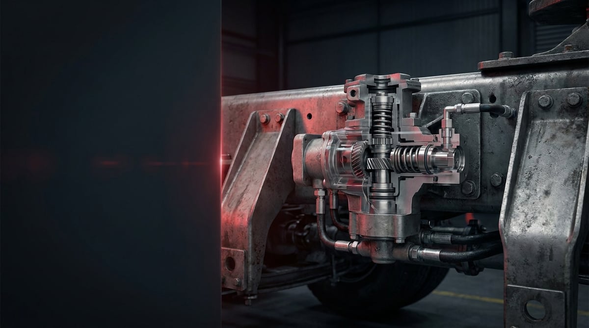
Every driver who uncouples a trailer and leaves it standing in the yard talks to this valve without realising it: he presses the red button, the air supply is cut, the spring brake actuators take over and the trailer settles onto its own park brake. Later, when the line has to be exhausted for a shunting move, the brake is released through that same valve. In the workshop it goes by names such as "the trailer button", "the park button" or "the release valve"; its technical name is the emergency / park-release valve. It looks small and usually sits somewhere along the chassis rail buried in dust and mud, but when it fails the trailer is either locked solid in the yard or — far more dangerous — fails to hold when it is supposed to be parked. This guide explains, in workshop language, what this valve does on heavy commercial vehicles and trailers, its typical failure patterns, how to diagnose it, how to replace it and how to maintain it.
This document has been prepared by the VADEN technical team, based on field experience with heavy commercial vehicle air brake systems and on OE component behaviour. The values given here are typical reference ranges; for exact torque, pressure and adjustment figures, always refer to the OE service manual of the vehicle, the trailer and the brake system. Last updated: July 2026.
What Is an Emergency / Park-Release Valve? Function and Operating Principle
The emergency / park-release valve is a pneumatic control valve that, via manually operated buttons, shuts off and exhausts the air in the supply line of a trailer or vehicle to apply the spring-brake park brake, and that — when required — uses the pressure remaining in the reservoir to release the brake temporarily so the unit can be manoeuvred.
Its operating principle rests on the basic safety logic of an air brake system: spring brake (spring-loaded diaphragm) actuators are released when pressure is present and applied when pressure is lost. In other words, loss of air is not a fault — it is a brake command. The valve puts exactly this behaviour into the driver's hand. When the control button is pulled out, the valve exhausts the trailer supply line and the spring brake line to atmosphere; the springs extend and the vehicle settles onto its park brake. When the button is pushed in, reservoir pressure is fed back to the actuators, the springs are compressed and the brake is released.
The second function of the valve is the emergency/shunt side. On a trailer that has been uncoupled or whose supply line has been broken, there is no line pressure and the trailer is braked. If some pressure still remains in the trailer reservoir, the "release" (park release / shunt) button routes this reservoir pressure to the actuators, releasing the brake temporarily and allowing the trailer to be pulled or manoeuvred out of position. As reservoir pressure drops, the brake reapplies on its own; this is deliberate safety behaviour of the system, not a fault.
On modern EBS-equipped trailers the picture is somewhat different. On the latest generation of semi-trailers and trailers, the park-release function often does not exist as a stand-alone valve; it is integrated into the trailer air control valve (TrCM / EBS park module). In these modules the park and shunt buttons, the supply check valve, the pressure protection stage and, on some types, the raise-lower control are combined in a single body. The practical consequence is this: although fault-finding remains valve-specific, the repair is usually solved not by replacing a single park valve but by replacing the complete module. So before you start diagnosing, always confirm from the body label and the port layout whether the trailer uses a stand-alone park valve or an integrated module; otherwise the correct part on the shelf becomes the wrong part.
This product group is known in the market by several names: park-release valve, trailer park valve, red-and-yellow button valve, shunt/release valve, Knorr-Bremse (Bendix) or WABCO type park valve. Although their functions are similar, the number of ports, the button combination and the internal control logic differ from one to another.
- Valve body and ports: Supply (reservoir) inlet, trailer/supply line connection, spring brake outlet and exhaust (vent) port. The ports are cast or laser-marked on the body with numbers according to ISO 6786: 1 = supply (reservoir) inlet, 2 = outlet (spring brake / trailer line), 3 = exhaust / vent. On multi-circuit types the supply and outlet pairs are numbered 11/12 and 21/22; that is, a change in the second digit indicates the second circuit of the same function.
- Control buttons: Push-pull buttons, generally red (trailer supply / trailer park) and yellow (vehicle park brake / release; black on some types). In European (ECE) practice the park brake button is yellow and the trailer supply button is red; the black button is specific to the US market and to older applications.
- Internal piston and spring assembly: The moving core that opens, closes or vents the air path depending on button position.
- Sealing elements: O-rings, valve seat faces and the button stem seal.
- Automatic pop-out mechanism: The safety stage that pushes the button out by itself when pressure falls below a defined threshold, thereby applying the brake.
- Check valve / pressure protection stage: An internal element on some types that prevents reservoir pressure from bleeding back.
Why is the "brake applies when the air is gone" logic used?
On a heavy commercial vehicle, the park and emergency brake work differently from hydraulic passenger car logic. The braking force is produced by springs; the air only compresses those springs and holds the brake released. In situations such as a burst hose, a broken coupling or loss of supply, the system automatically falls to the safe side, that is, to the applied position. The park-release valve is the manual control interface of this behaviour.
Difference between the tractor-side valve and the trailer-side valve
The hand brake valve (park brake valve) on the tractor side is generally inside the cab and is used constantly by the driver. The park-release valve on the trailer, on the other hand, is positioned along the chassis rail so it can be reached from outside; it provides park and manoeuvring control for an uncoupled trailer. Both work on the same logic but have different port layouts and durability requirements.
On the pair of lines that connects these two, the most useful piece of information in the field is the colour code of the coupling heads. Under EN 15807, the pneumatic coupling heads between tractor and trailer are distinguished by colour: red = supply (emergency) line, yellow = service (control) line. The red line charges the trailer reservoir and, when interrupted, applies the park/emergency brake; the yellow line carries the driver's brake pedal command. Reading the valve ports together with this colour logic is the most practical safeguard against the port mix-up described in the warning below — remember that the line coming from the red coupling must go to the supply port (1) of the valve, and the yellow line to the service/control side.
The pop-out (automatic release) function
When system pressure falls below the safety threshold, the button is expected to pop out by itself, so that the vehicle cannot be moved while pressure is insufficient. If the button does not behave this way, the valve has lost its most critical safety function, and that alone is grounds for replacement.
| Type / Application | Control | Typical use | Note |
|---|---|---|---|
| Trailer park-release valve (twin button) | Red + yellow (black on some types) button | Semi-trailer, drawbar trailer, tanker trailer | Knorr-Bremse, WABCO and Bendix equivalent types |
| Single-button park valve | Single push-pull button | Light trailer, agricultural trailer, special equipment | Park function only |
| In-cab hand brake valve | Lever / button operated | Tractor unit and truck cab | Driver operated, in constant use |
| Chassis-mounted release (shunt) valve | Push button | Manoeuvring an uncoupled trailer | Temporary release using reservoir pressure |
| Combined valve with pressure protection | Button + internal protection stage | Multi-circuit trailer systems | Maintains circuit priority |
| EBS park module (integrated) | Button group on the module | Modern EBS-equipped semi-trailer | No separate valve; complete module replacement |
Part number verification: Park-release valves look almost identical from the outside; the difference lies in the number of ports, the distribution of button functions and the internal control logic. A valve of the wrong type can cause the trailer not to settle onto its park brake when uncoupled, or not to release at all. Before fitting, always verify the OE number of the old valve, the port layout (the 1/2/3 or 11-12/21-22 numbers on the body) and the button colour/function assignment.
Failure Symptoms and Diagnosis
Faults on this valve fall into two main groups: it does not control (the button fails to perform its function) and it does not hold / it leaks (loss of internal sealing). The second group is the more insidious, because it can slowly release the brake of a parked vehicle. The table below is the starting point for field diagnosis.
| Symptom | Possible Cause | Check / Verification |
|---|---|---|
| Button will not stay pushed in, keeps popping out | Low supply pressure, internal leak, faulty pop-out stage | Measure reservoir pressure with a gauge; repeat the behaviour while above the threshold |
| Park brake does not apply although the button is pulled out | Internal piston sticking, exhaust port (3) blocked, spring brake line not exhausting | Verify that spring brake line pressure drops to zero while the button is pulled out |
| Park brake will not release, trailer stays locked | Supply line blocked/frozen, internal valve blockage, insufficient reservoir pressure | Measure reservoir and supply line pressure separately; check for the possibility of a frozen line |
| Continuous air blowing from the exhaust port of the valve | Hardened O-rings, wear on the internal piston seat face, fatigued button stem seal | Apply a soapy water test in both button positions |
| Brake releases by itself over time while parked | Pressure bleeding into the spring brake actuators due to an internal leak | Chock the vehicle for safety; observe spring brake line pressure over a long period |
| The release (shunt) button does not free the brake for manoeuvring | No pressure left in the trailer reservoir, check valve failure, jammed button mechanism | Read reservoir pressure; if pressure is present the valve is at fault, if not it is a charging problem |
| Button mechanically stiff / does not return | Dirt, corrosion, ice, broken internal spring | Clean the body and check button movement by hand |
| Does not work in the cold, recovers once warm | Moisture in the system - internal freezing; inefficient dryer | Check reservoir water draining and the condition of the dryer cartridge |
Pressure verification with a gauge
The most reliable diagnosis is to connect a gauge to the reservoir outlet and to the spring brake line and then operate the buttons in turn. When the button is pushed in, the spring brake line must rise rapidly to reservoir level; when it is pulled out, it must fall rapidly to zero. Slow filling points to a supply restriction, slow exhausting to an exhaust/piston problem, and failure to fall to zero at all to an internal blockage.
Leak (sealing) test
With the system fully charged, the engine off and the vehicle chocked, soapy water is applied to the valve body, the port connections and the exhaust outlet. The test must be carried out separately in both button positions; many valves leak in one position only, and a single-position test will miss that fault.
Pop-out threshold and function check
By bleeding the system down in a controlled manner, you observe whether the button pops out by itself at the safety threshold. This test must always be carried out with the vehicle chocked, on level ground and with the surrounding area made safe. If the button does not pop out, the valve is allowing the vehicle to move even when pressure is insufficient; this is an unacceptable safety defect.
Standards and further reading
This subject is governed by the equipment rules for air-braked commercial vehicles. In the United States the federal air brake standard, FMVSS 121 (49 CFR 571.121) defines the reservoirs, protection and timing a compliant system must provide, and Europe applies the equivalent limits of UNECE Regulation No. 13. For further detail, see the illustrated reference guide at airbrakecompressor.com. Always confirm specific figures against the current regulation and the vehicle manufacturer service data.
Outside the United States the equivalent duties sit in national law. In the United Kingdom, regulation 18 of the Road Vehicles (Construction and Use) Regulations 1986 requires every part of the braking system to be maintained in good working order. In Canada, air brake systems fall under the Motor Vehicle Safety Regulations, which contain CMVSS 121.
Replacement / Installation Steps
Personal protective equipment (PPE) and safety: Wear work gloves and safety glasses. Before starting work, move the vehicle onto level ground, always chock the wheels and exhaust all pressure from the brake system. Because this valve controls the park brake, the vehicle may be left without braking during removal — the mechanical chocks must be your only safeguard. A port or line loosened under pressure can cause serious injury from a flying component. The engine and the ignition must be switched off.
- Make the vehicle safe: Park on level ground, chock the wheels, secure the combination if a tractor unit is coupled, and mark off the working area.
- Exhaust the pressure completely: Drain all circuits through the reservoir drain valves; verify with a gauge that the system is at zero pressure.
- Mark the lines and ports: Label or photograph every line before removal. Write the labels not by guesswork but by reading the ISO 6786 port numbers on the body: 1 = supply (reservoir) inlet, 2 = outlet (spring brake / trailer line), 3 = exhaust / vent; on multi-circuit types 11/12 are the supply pair and 21/22 the outlet pair. If the cast numbers are hidden under mud or paint, clean the body until they are legible. Also note the coupling colour code (red = supply, yellow = service). Mixing up the ports is the most common mistake in this job.
- Disconnect the air lines: Carefully separate the fittings or quick connectors and cap or protect the line ends against contamination.
- Remove the old valve: Undo the bracket/panel bolts and separate the valve from its mounting face; on in-cab types, take care not to damage the console panel.
- Verify the new valve by comparison: Check the OE number, the port count and layout and their number markings, the thread sizes and the button colour/function assignment of the new VADEN valve side by side against the old part.
- Clean the surface and the lines: Clean the mounting face, the fitting ends and the insides of the lines; no swarf, rust or old gasket residue must enter the system.
- Fit the new valve: Tighten the bracket bolts progressively and to the OE torque without distorting the body; access to the valve buttons must remain free.
- Connect the lines to the correct ports: Fit the supply, spring brake and trailer lines according to your labels and the port numbers; tighten the fittings to the OE torque and do not overtighten.
- Charge the system and carry out a leak test: Start the engine and bring the system up to full pressure; check for leaks with soapy water at all ports and at the exhaust outlet, in both button positions.
- Perform the function and pop-out test: Operate the buttons in turn to confirm that the brake applies and releases and that the button pops out by itself when pressure drops; then complete the job with a controlled low-speed brake test.
Points to Watch (Common Mistakes)
The most critical mistake — working without chocks: This valve controls the park brake. Even if the spring brake line has been exhausted during removal, the brake may release unexpectedly during fitting or testing. Wheel chocks are not optional; they are the first and the last step of the job.
Mixing up ports and button functions: Swapping the line connections of the red and yellow (black on some types) buttons can cause the trailer not to settle onto its park brake when uncoupled — that is, the most dangerous type of failure. Mark the port numbers and the coupling colours together before removal, and test each function separately after fitting.
- Treating a leak as "normal": Continuous blowing from the exhaust port is not normal; it is the first sign of a loss of internal sealing.
- Skipping the pop-out test: The valve may apply and release correctly while the pop-out stage is faulty; it must be tested separately.
- Forcing a frozen valve: Forcing a button that has seized in winter with a screwdriver breaks the mechanism permanently; the ice must first be allowed to thaw and the source of moisture eliminated.
- Dirty line ends: Swarf and rust entering the system permanently damage the valve seat face and will finish off the new part in a short time.
- Wrong torque: Overtightening damages the body and the threads, undertightening creates leaks; follow the OE values.
- Mistaking an integrated module for a single valve: If the park function on an EBS trailer is inside the trailer air control valve (TrCM), looking for a stand-alone park valve is a waste of time; start the parts search from the body label.
- Ignoring the root cause: If the valve has failed because of moisture, a replacement carried out without addressing the dryer and reservoir draining is only a temporary fix.
Technical Values and Check Points
The values below are typical/general reference ranges for heavy commercial vehicle air brake systems. Exact values vary with the vehicle, the trailer, the valve type and the axle configuration; the OE service manual is always definitive.
| Parameter | Typical / General Reference | Note |
|---|---|---|
| System operating pressure | ~8–10 bar (approx. 116–145 psi) | Reservoir/circuit pressure; varies according to OE |
| Trailer supply line pressure | ~6.5–8.5 bar | Red coupling (supply), permanent line |
| Full release pressure of the spring brake | General reference above ~5.5–6.5 bar | Below this the brake remains partially applied |
| Pop-out (automatic release) threshold | General reference range ~3–5 bar | Specific to the valve type; the OE value is definitive |
| Operating temperature range | Approximately -40 °C to +80 °C | Ambient and component temperature |
| Permissible leakage | Very low / negligible according to the OE limit | Assessed by the rate of reservoir pressure drop |
| Exhaust behaviour of the spring brake line | Time for line pressure to fall to zero after the button is pulled out | An extended time indicates a restriction at the exhaust port (3) or an undersized line bore; measure comparatively against a sound valve on the same chassis |
General torque references for the fasteners are given below. These are starting values; the OE manual must be used for the final torque.
| Connection | Typical Torque Range | Note |
|---|---|---|
| Bracket / mounting bolts (M6) | ~8–12 Nm | Tighten carefully on panel-type installations |
| Bracket / mounting bolts (M8) | ~20–25 Nm | Tighten progressively and evenly |
| Bracket / mounting bolts (M10) | ~40–50 Nm | Varies according to OE |
| Air line fittings | According to manufacturer specification | Overtightening damages threads and ports |
Take pressure measurements with a calibrated gauge and with the system fully charged. When testing the pop-out threshold, reduce the pressure in a controlled, gradual manner; a sudden exhaust both distorts the measurement and causes the vehicle to go onto the brake unexpectedly. Make sure the chocks stay in place throughout the test.
- Verify the supply and spring brake line pressures separately.
- Observe that the spring brake line drops rapidly to zero when the button is pulled out.
- Repeat the soapy water test in both button positions.
- Confirm that the button pops out by itself at the pop-out threshold.
- Look for cracks, broken tabs and excessive free play on the button surfaces.
- Clean and inspect the body area for corrosion and mud build-up.
- Confirm that the port numbers and the button function labels remain legible.
Maintenance and Service Life
The emergency / park-release valve is not a scheduled replacement item; its life depends largely on the quality of the air fed into the system and on the external conditions it is exposed to. Because it sits under the chassis, road salt, mud and moisture reach the body directly. The threat from inside is moisture and oil: in a system with a worn-out dryer the valve's O-rings harden, the seat faces wear and internal leakage begins.
- Air quality: Replace the dryer cartridge on time; moisture is the number one enemy of the sealing elements inside the valve.
- Reservoir draining: Drain the water drain valves regularly; accumulated water freezes inside the valve in winter and locks the button.
- Periodic function check: At every brake service, test the park and release functions separately, together with the pop-out behaviour.
- External cleaning: Clean mud and salt deposits from around the body; corrosion seizes the button stem.
- Mounting and vibration check: Inspect the bracket bolts for looseness and the lines for chafing or wear.
- Leak monitoring: Monitor the rate of pressure drop on a vehicle left parked for a long period; an accelerating drop is an early warning.
A quality park-release valve will work trouble-free for years in a system supplied with clean, dry air. In a damp, dirty and neglected system, on the other hand, even the best valve will fail early. For this reason, regular maintenance of the air preparation chain (compressor, dryer, reservoir draining) determines valve life just as much as the valve replacement itself. You can review the VADEN product families at the two ends of this chain: the air brake compressors and dryer purge valve (air dryer) groups cover the components that directly determine the pressure and moisture quality of the air reaching the valve.
A correctly selected emergency / park-release valve, supplied with clean air and fitted properly, is the basic condition for a trailer to be left safely in the yard and manoeuvred without trouble when required. The VADEN ORIGINAL park and release valve product family is manufactured with port layouts suited to heavy commercial vehicle and trailer systems, OE-equivalent control logic and a body construction that withstands field conditions; used together with correct part number matching and the OE service manual, it provides reliable, long-lasting park brake control.
Related categories: Park Release Emergency Valve · Park Release Emergency Valve
Related technical guides: ABS Wheel Speed Sensor & ECU: Faults, Replacement & Care · Brake Caliper Overhaul Kit: Guide Pins, Boots & Adjuster · Air Processing Unit (APU/EAC): Faults, Replacement & Care · Pressure Limiting Valve: Faults, Replacement & Maintenance · Four-Circuit Protection Valve: Faults, Diagnosis & Replacement
Application and compatibility: Vehicle compatibility catalogue · Engine compatibility catalogue
Main guide: Truck Air Brake Valves Explained: Types, Functions and Failure Symptoms
Tags
Frequently Asked Questions
- How do I recognise a faulty park-release valve?
- The most common signs are: the button will not stay pushed in, the park brake does not apply although the button is pulled out, air blows continuously from the exhaust port, and the brake releases by itself over time while parked. A definitive diagnosis is made by connecting a gauge to the spring brake line and observing the pressure behaviour in each button position.
- What do the red and yellow buttons do?
- In European (ECE) practice the yellow button controls the park brake and, when pulled out, sets the vehicle/trailer onto its park brake; the red button controls the trailer supply line and, when pulled out, applies the trailer park brake. On some types and in US-derived applications, a black button takes the place of the yellow one. Because the button colour-to-function assignment can vary with the valve type, the OE documentation, the port numbers on the body and a comparison with the old part must always be taken as the reference during fitting.
- How do I find the OE number of my valve?
- Do not rely on a single marking; use four pieces of information together. First, the cast or laser number on the body — it is usually on the side face of the valve body or near the mounting flange, and if it is buried under mud and paint, clean it until it is legible. Second, the port layout: how many ports there are and which ISO 6786 numbers appear on the body (1 / 2 / 3, or 11-12 / 21-22). Third, the number of buttons and their colour-to-function assignment. Fourth, the port thread sizes and the mounting hole spacing. Visual similarity alone is not enough: two valves that look identical from the outside may differ in internal control logic and port function assignment, and an incorrect match can result in the park brake not applying at all. Note these four items and compare them with the cross-reference list in the VADEN catalogue; if in doubt, request technical support with photographs of the old part.
- Why does the trailer brake by itself when it is uncoupled?
- Because in a heavy commercial brake system the park brake force is produced by springs, and the air only compresses those springs and holds the brake released. When the supply line is interrupted, the pressure is lost and the springs extend to apply the brake. This is not a fault but deliberate safety behaviour of the system.
- I pressed the release (shunt) button but the brake did not release — why?
- This function uses the pressure remaining in the trailer reservoir. If the reservoir is empty, the brake will not release even if the button works; air must first be fed into the system. If there is sufficient pressure in the reservoir and the brake still does not release, an internal valve blockage, a blocked line or freezing should be considered.
- If the button keeps popping out, is the valve at fault?
- Not always. Measure reservoir pressure first: if the pressure is below the pop-out threshold, the valve is behaving correctly and the real problem is on the supply/charging side. If the button still pops out while pressure is at a normal level, an internal valve leak or a faulty pop-out stage comes to the fore.
- What should I do if the valve freezes in winter?
- The source of the freezing is moisture in the system. In the short term you must let it thaw without forcing the valve; the permanent solution is to replace the dryer cartridge and to drain the reservoir water regularly. Forcing a frozen button mechanically will break the mechanism.
- Can I replace the valve myself?
- The job requires the vehicle to be secured with chocks, the pressure to be fully exhausted, the ports to be connected correctly, and leak, function and pop-out tests to be carried out after fitting. Because the park brake is a direct safety function, it is recommended that the work be carried out by an authorised heavy commercial vehicle workshop unless you have the proper equipment and experience.
- What happens if I fit the wrong valve?
- A valve with a different port layout or button function can cause the trailer not to settle onto its park brake when uncoupled, the brake not to release at all, or the pop-out safety feature to be disabled. Always match against the OE number of the old part, the port numbers and the system type.
- I cannot find a separate park-release valve on my trailer, which part do I need?
- On the latest generation of EBS-equipped semi-trailers this function is often not a stand-alone valve; it is integrated into the trailer air control valve (TrCM / EBS park module), where the park and shunt buttons, the supply check valve and the pressure protection stage sit in a single body. The repair is then solved by replacing the complete module rather than one valve. Confirm the layout from the body label and the port arrangement before ordering.
Related Articles

ABS Brake System: How It Works, Warning Light and Faults
Learn how the ABS brake system works on heavy trucks, why the warning light comes on, how to diagnose sensor faults, and the correct replacement steps.
Brake Chamber, Diaphragm & Hose: Faults, Replacement, Care
Learn how to spot a leaking brake chamber, measure push rod stroke, cage the power spring safely and replace the unit and hose without risk on heavy trucks.
Air Dryer Purge Valve: Faults, Replacement and Maintenance
How a truck air dryer purge valve works, spotting leak and freezing symptoms, safe step-by-step replacement and keeping the air brake system dry.


