Lift Axle Valve: Faults, Replacement and Maintenance Guide
Lift axle valve guide for trucks and trailers: how it works, fault symptoms, pressure diagnosis, step-by-step replacement and maintenance checkpoints.
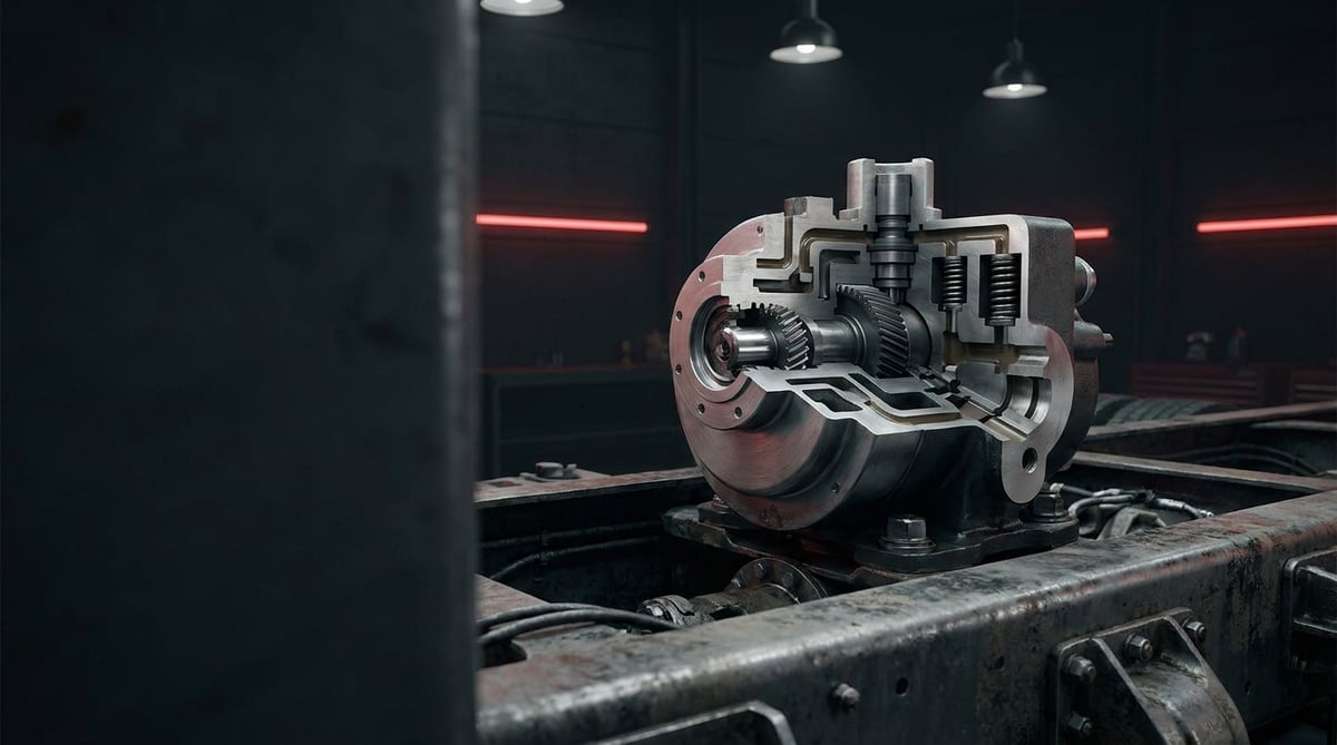
When a complaint comes in on a three-axle tractor unit or a multi-axle trailer — "the lift axle won't raise", "it drops by itself on the road" or "the axle stays down even when empty" — one of the first components questioned in the field is the lift axle valve. This valve exhausts the load-carrying suspension bellows of the auxiliary axle and pressurises the lift bellows to raise the axle clear of the road; when load is applied or a command is given, it lowers the axle back onto the ground. In the workshop it is commonly called the "lift axle valve", the "axle lift valve" or simply the lift valve. A malfunctioning lift valve is not only a tyre and fuel cost issue; it creates a direct risk in terms of axle load distribution, traction and regulatory compliance. This guide covers the valve's operating logic, its faults, diagnosis, and replacement/maintenance practice in plain workshop language.
Editor's note (E-E-A-T): This technical guide has been prepared by the VADEN technical team based on field experience with heavy commercial vehicle air suspension and pneumatic control systems, together with OE manufacturer documentation practice. The values in the text are typical reference ranges; for vehicle-specific exact pressure, torque and raise/lower threshold values, the current OE service manual of the relevant vehicle must always be taken as the basis. When using a liftable axle, the maximum axle loads stated on the vehicle registration document and the lift axle usage conditions defined by the manufacturer are binding. Last updated: July 2026.
Heavy commercial vehicle air brake systems are designed within the framework of ECE R13 (UN/EU braking regulation) and ISO 611.What Is a Lift Axle Valve? Function and Operating Principle
The lift axle valve is a pneumatic control valve that, on air-suspended heavy commercial vehicles, exhausts the air from the load-carrying bellows and sends pressure to the lift bellows to raise the auxiliary (lift) axle clear of the road, and lowers the axle again in response to load or a control signal.
Its operating principle is based on feeding two bellows groups in opposite directions. With the axle down, the load-carrying bellows are pressurised and carry the load while the lift bellows are empty. When a command is given, the valve reverses this state: it rapidly exhausts the load-carrying bellows through the exhaust port and at the same time routes supply air to the lift bellows; the bellows inflate, pull the axle carrier upwards and the tyres lift clear of the ground. On lowering, the flow reverses, the load-carrying bellows refill and the axle settles back onto the ground in a controlled manner.
The critical point is that these two movements occur simultaneously and in the correct sequence. For this reason most lift axle valves incorporate a quick release function in the body: the air from the load-carrying bellows is discharged to atmosphere through the valve's own exhaust port instead of travelling back along a long line. Many types also include a stage that limits the pressure fed to the lift bellows.
The valve does not work alone; it is the final link in a control chain. In OE architecture this chain typically follows the sequence: levelling valve - ECAS/EBS control unit - solenoid (magnet) valve block - lift axle valve - bellows. The levelling valve determines chassis height and therefore load-carrying bellows pressure; the ECAS/EBS unit evaluates this information together with speed, axle load and driver demand; the solenoid valve block converts the electrical decision into pneumatic switching; and the lift valve actually feeds and exhausts the bellows lines. In systems derived from Knorr-Bremse, Wabco/ZF, Bendix and Haldex the naming of these layers varies, but the logic is the same. On trailers in particular, keep in mind that the lift logic is often defined not in the valve itself but in the parameters of the trailer EBS/ECAS unit — behaviour that looks like a "valve fault" sometimes originates from a configuration in the unit.
- Body: Usually cast aluminium alloy; houses the supply, load-carrying bellows, lift bellows and exhaust ports.
- Port markings: According to the common body marking convention used on pneumatic components, 1 = supply, 2 = delivery / bellows line, 3 = exhaust, 4 = control (pilot); on dual-circuit types the two circuits of the same function are shown as 11-12 and 21-22. These numbers are not an OE specification value but a marking convention read on the body; they must be verified on every vehicle.
- Control piston / diaphragm: Transmits the pilot signal or lever movement to the internal valve assembly.
- Double-acting valve assembly: Opposing poppets that feed one line while opening the other to exhaust.
- Quick release stage: Provides fast raising by venting the load-carrying bellows air by the shortest route.
- Pressure limiting stage: Limits the pressure fed to the lift bellows (fixed or adjustable depending on type).
- Load sensing (pilot) port: Reads load-carrying bellows pressure and determines the automatic lowering threshold.
- Solenoid coil (on electro-pneumatic types): Controls the valve via a cab switch or an ECU signal.
- O-rings and sealing elements: Elastomer seals that prevent internal leakage between ports.
Manual, Automatic and Electro-Pneumatic Types
On the manual type the driver raises and lowers the axle using a control valve or lever in the cab; the system is entirely pneumatic. On the automatic (load-sensing) type the valve continuously reads load-carrying bellows pressure: when the load rises above a certain threshold the axle lowers by itself, and when the load is removed it can be raised again. On electro-pneumatic types the command arrives via a solenoid; if the vehicle is ECAS/EBS equipped, the raise-lower logic is defined in the electronic unit and the valve only performs the final-stage pneumatic switching. These three architectures are not interchangeable; port count, pilot input and control logic differ.
Difference Between a Pusher Axle and a Tag Axle
On 6x2 tractor units the position of the auxiliary axle directly affects the valve's control logic. An auxiliary axle located ahead of the drive axle is called a pusher axle, while one located behind it is called a tag axle; in most applications the tag axle is of a self-steering design. On a pusher axle, because load is transferred ahead of the drive axle, the automatic lowering threshold is generally defined to engage earlier, and the load change on the drive axle during traction help is more pronounced.
On a tag axle the lowering threshold is set according to the total load distribution of the rear axle group; on self-steering types the axle must be able to centre mechanically during raising and lowering, otherwise tyre scrub is seen during manoeuvring. On multi-axle combinations the lift sequence is also fixed: which axle rises first and which lowers first as load increases is defined by the vehicle manufacturer and must not be changed arbitrarily. For this reason, saying simply "lift axle valve" is not enough when selecting a replacement; whether the axle is a pusher or a tag, and the lift sequence on that vehicle, are also part of the match.
Traction Help Function
On many vehicles the lift valve is used together with a traction help function. When pulling away on a slippery surface or a gradient, the auxiliary axle is briefly raised or the load-carrying bellows pressure is reduced; part of the load is thus transferred to the drive axle and wheel spin is reduced. By design this function is temporary: above a certain low speed and after a certain time, the system returns to normal by itself. Speed, duration and axle load limits vary by vehicle and market; in practice the maximum axle loads stated on the vehicle registration document and the lift axle usage conditions defined by the manufacturer are binding. Likewise, the lift axle is designed to be used only when empty or partially loaded; when the permissible load of the remaining axles is exceeded, the axle must be on the ground. The automatic lowering threshold is therefore not a comfort feature but a safety and compliance function.
Typical Applications and Matching
| Application / Segment | Example Use | Key Feature |
|---|---|---|
| 3-axle tractor unit (6x2, pusher axle) | Raising the auxiliary axle ahead of the drive axle | Early-engaging automatic lowering threshold + traction help |
| 3-axle tractor unit (6x2, tag axle) | Axle behind the drive axle, mostly self-steering | Threshold based on rear axle group load distribution, centring requirement |
| 4-axle truck / concrete mixer | Front or rear lift axle management | High load threshold, robust body |
| Multi-axle trailer / low-bed | Axle lifting on the empty return run | Simple pneumatic control, quick release; logic mostly in the trailer EBS/ECAS |
| Bus / midibus (auxiliary axle) | Axle management according to passenger load | Precise threshold, quiet and progressive switching |
| ECAS/EBS equipped vehicle | Electronically controlled lifting | Solenoid control, integrated operation with the ECU |
Part number verification: Although lift axle valves look very similar externally, the port count and layout, pilot input arrangement, lift bellows pressure limit, automatic lowering threshold, control type (manual / pneumatic pilot / solenoid) and coil voltage vary by type. The wrong valve type can result in the axle not rising at all, dropping by itself on the road, or rising while loaded. Before installation, verify the match using the OE part number, the port numbers on the body (1/2/3/4 or 11-12 / 21-22), the control type and, where applicable, ECAS/EBS compatibility; do not rely on visual similarity.
Standards and further reading
This subject is governed by the equipment rules for air-braked commercial vehicles. In the United States the federal air brake standard, FMVSS 121 (49 CFR 571.121) defines the reservoirs, protection and timing a compliant system must provide, and Europe applies the equivalent limits of UNECE Regulation No. 13. For further detail, see the on-road braking performance requirement in 49 CFR 393.52. Always confirm specific figures against the current regulation and the vehicle manufacturer service data.
Outside the United States the equivalent duties sit in national law. In the United Kingdom, regulation 18 of the Road Vehicles (Construction and Use) Regulations 1986 requires every part of the braking system to be maintained in good working order. In Canada, air brake systems fall under the Motor Vehicle Safety Regulations, which contain CMVSS 121.
Fault Symptoms and Diagnosis
Faults are usually reported as "the axle won't raise", "the axle won't lower" or "it lowers by itself"; however, the same symptoms can also stem from a leaking bellows, a blocked line or an electrical control fault. The table below summarises the symptoms most frequently encountered in the field together with their likely causes and verification methods.
| Symptom | Possible Cause | Check / Verification |
|---|---|---|
| Axle does not rise at all despite the command | Low supply pressure, internal valve poppet stuck, no air reaching the lift bellows | Measure the pressure at the supply port (1); connect a gauge to the lift bellows line and check whether pressure builds on command |
| Axle rises but slowly / only partly | Load-carrying bellows not fully exhausting, quick release stage restricted, exhaust blocked | Listen to the discharge rate at the exhaust port (3); measure whether residual pressure remains in the load-carrying bellows line |
| Raised axle lowers by itself on the road | Lift bellows or its line leaking, internal leakage in the valve, pilot signal dropping out | Soap-bubble test on the bellows and fittings with the axle raised; monitor pressure drop against time |
| Axle does not lower despite load being applied | Automatic lowering (load-sensing) stage faulty, pilot line blocked, threshold incorrectly set | Measure pilot/load-carrying bellows pressure under load and compare with the threshold value |
| Axle stays down when the vehicle is empty and cannot be raised | No supply to the control switch/solenoid, valve seized, lines cross-connected | Measure voltage at the solenoid terminals; compare port connections with the body numbers and the schematic |
| Continuous air consumption, compressor runs excessively | Constant leakage from the valve exhaust port, internal poppet not closing fully | Carry out a soap test at the exhaust port with the system at nominal pressure |
| Axle lands hard when lowering, knocking noise | Load-carrying bellows filling too fast, restrictor/damping stage faulty, bellows damaged | Observe the rate of pressure rise in the load-carrying bellows during lowering; check the condition of the bellows and bump stop |
| Erratic raising-lowering in cold weather | Moisture in the system, icing inside the valve, inefficient air dryer | Check the air dryer and reservoir draining; trace the source of moisture |
Distinguishing Faults by Pressure Measurement
The most reliable diagnosis is simultaneous pressure measurement at the valve's inlet and outlet ports. If system pressure is present at the supply port but no pressure builds in the lift bellows line on command, the problem is inside the valve. If pressure does build but the axle still does not rise, the culprit is usually the bellows, a mechanical linkage or a seized axle carrier. If residual pressure remains in the load-carrying bellows line during lifting, the exhaust/quick release side is restricted.
Leak Testing and Identifying Internal Leakage
With the axle in the raised position, the system is left at nominal pressure; the lift bellows line, the fittings and the valve body are scanned with soap solution. If no external leak is visible but the axle gradually lowers, internal leakage (a poppet not closing fully) is likely. Replacing the valve without making this distinction is a common mistake; the lift bellows itself can also crack over the years and produce the same symptom.
Signal Checks on Electrical Controls
On electro-pneumatic types, fault finding must start with the electrics: is there voltage at the cab switch or ECU output, is the coil resistance plausible, is the connector corroded or water-ingressed. If voltage reaches the coil but the valve does not switch, the fault is in the valve; if no voltage arrives, the problem is in the wiring, the switch or the control unit. On EBS/ECAS equipped vehicles, reading the fault memory significantly reduces the measurement workload; on trailers it should additionally be checked that the lift parameters are correctly defined in the trailer unit.
Replacement / Installation Steps
Personal protective equipment (PPE) and safety: A raised axle can drop suddenly the moment the air in the lift bellows is released; compressed air and a moving axle can cause serious injury. Before starting work, secure the vehicle on level ground, chock the wheels, stop the engine, switch off the ignition and release the pressure in the suspension circuit in a controlled manner. Support the lift mechanism mechanically or work with the axle in the lowered position; never go under the axle without support. Wear safety glasses and gloves.
- Secure the vehicle: Park on level ground, chock the wheels, switch off the engine and turn the ignition off.
- Bring the axle to a safe position: Lower the lift axle to the ground or support it mechanically with suitable equipment.
- Release the pressure: Vent the suspension and lift circuits in a controlled manner; confirm on the gauge that pressure has dropped.
- Isolate the electrics (if fitted): On electro-pneumatic types switch off the battery master switch, disconnect the solenoid connector and inspect the pins for corrosion or water traces.
- Mark the lines: Label or photograph the supply, load-carrying bellows, lift bellows, pilot and exhaust lines before disconnecting. Also note the port numbers on the body: in the common marking convention 1 = supply, 2 = delivery / bellows line, 3 = exhaust, 4 = control (pilot); on dual-circuit types the circuits are shown as 11-12 and 21-22. Since the numbers can be arranged differently depending on the valve type, compare the layout you read with the vehicle schematic. Mixing up ports is the most common mistake made on this valve.
- Disconnect the air lines: Loosen the fittings with the correct spanner and separate the pipes without forcing them; temporarily plug the open port openings to prevent dirt ingress.
- Remove the old valve: Undo the bracket and mounting bolts and take the valve off; check the bracket for cracks, distortion and corrosion.
- Prepare the mounting surface: Clean off dirt, rust and old gasket residue; renew any damaged brackets, bolts and hoses.
- Position the new valve: Fit the correct valve type to its bracket with the exhaust port facing downwards and the port orientation matching the vehicle layout; tighten the bolts progressively to the torque specified by the manufacturer.
- Reconnect the lines: Following the labels and port numbers, connect the supply, load-carrying bellows, lift bellows and pilot lines to the correct ports; tighten the fittings so they seal but without overtightening. Seat the solenoid connector fully and fit its lock if present.
- Carry out function and threshold testing: Charge the system to nominal pressure and leak-test all connections; raise and lower the axle several times to confirm that the movement is fast and progressive. Then load and unload the vehicle to check that the automatic lowering threshold works, that the axle stays down when loaded, and that traction help (if fitted) returns to normal by itself. On EBS/ECAS equipped vehicles, clear and re-read the fault memory.
Points to Watch (Common Mistakes)
The most critical mistake — mixing up ports: Swapping the load-carrying bellows and lift bellows lines can cause the axle to operate in reverse, overstress the bellows with excessive pressure and allow the axle to rise on a loaded vehicle. This is a serious risk both for the vehicle and for road safety. Always label the lines before removal, compare the port numbers on the body (1/2/3/4, or 11-12 / 21-22 on dual circuits) with the vehicle schematic, and carry out the first test after installation with the vehicle empty.
Disabling the automatic lowering function: Bypassing the load-sensing lowering stage, blanking off the pilot line with a plug or arbitrarily changing the threshold leads to axle overload, brake imbalance and legal non-compliance. A faulty stage is not bypassed — it is repaired or the valve is replaced.
- Relying on visual similarity and fitting a valve with a different control type (solenoid-operated instead of manual, or a different coil voltage).
- Fitting a valve specified for a pusher axle to a vehicle with a tag axle (or vice versa), causing the lowering threshold not to match the vehicle layout.
- Ignoring the pressure limiting stage and feeding full system pressure to the lift bellows — bellows life is shortened.
- The exhaust port facing upwards or being blocked — water/dirt accumulation, freezing in winter and slow lifting.
- Working without releasing the pressure or supporting the axle — risk of the axle dropping suddenly and causing serious injury.
- Replacing the valve directly without first ruling out a leaking bellows or a cracked hose.
- Reusing hardened O-rings and seals; fitting a new valve without cleaning a corroded connector.
- Failing to verify the port layout and control type when selecting a replacement valve — with VADEN ORIGINAL lift axle valve references too, the first check to make before installation is to confirm that the port layout and control type on the body match the removed OE valve exactly.
- Handing the vehicle back without verifying the loaded/empty function test after installation.
Technical Values and Check Points
The values below are typical / general reference ranges for heavy commercial vehicle axle lift systems; they vary by vehicle and valve type, and the OE service manual is authoritative for exact values.
| Parameter | Typical Reference Range | Note |
|---|---|---|
| System supply pressure | ~8–12.5 bar (≈116–181 psi) | Varies by vehicle and circuit |
| Lift bellows working pressure | Typically ~6–8 bar (≈87–116 psi), limited according to type | Determined by the pressure limiting stage |
| Load-carrying bellows pressure | Variable with load, typically ~0.5–8 bar | Depending on empty/laden condition |
| Automatic lowering threshold | Specific to the vehicle and axle load; derived from load-carrying bellows pressure | The OE specification is authoritative and must not be changed arbitrarily |
| Raise/lower time | Use a comparative acceptance criterion rather than a numeric target: compare against a reference measurement taken on the same vehicle (or on a healthy vehicle of the same type) | A marked increase against the reference indicates a restricted exhaust, a blocked line or a leak |
| Permissible internal leakage | In practice "zero" is the target; measurable leakage = fault | There should be no continuous bubbling in the soap test |
| Operating temperature range | Approx. −40 °C to +80 °C | Elastomer and freezing limit |
| Solenoid supply voltage (electrical type) | Generally 12 V or 24 V DC | According to the vehicle system; must not be mixed up |
Connection torques vary by type and bolt size; the values below are for general reference only.
| Connection | Typical Torque Range | Note |
|---|---|---|
| Body/bracket mounting bolt (M8) | ~20–30 Nm | Tighten progressively and crosswise |
| Body/bracket mounting bolt (M10) | ~40–55 Nm | The OE value is authoritative |
| Air line fitting | According to manufacturer specification | Do not overtighten; do not strip the thread |
| Solenoid coil retaining nut | According to manufacturer specification (typically low torque) | Do not crush the coil body |
Field tip: With an "axle won't raise" complaint, connect a pressure gauge to the lift bellows line and give the command before removing the valve. If pressure rises, the valve is doing its job; the problem is in the bellows, the mechanical linkage or a seized carrier arm. This single measurement prevents a significant share of unnecessary valve replacements.
- Is the system pressure at the supply port (1) within the OE range?
- Does pressure build in the lift bellows line on command, and does the load-carrying bellows line exhaust fully?
- Has the raise and lower time increased noticeably compared with a healthy reference measurement?
- Does the axle hold its pressure for several minutes in the raised position (no internal/external leakage)?
- Does the automatic lowering threshold engage and the axle settle on the ground when load is applied?
- Does traction help (if fitted) operate for a limited time/speed and return to normal by itself?
- Is the exhaust port (3) free and facing downwards, is the connector dry and is the coil voltage correct for the vehicle?
Maintenance and Service Life
The lift axle valve is a long-lasting component when supplied with clean, dry air; its real enemies are moisture, dirt, vibration and corrosion caused by road salt. The valve is usually located under the chassis in an area exposed to mud and water spray, and because the raise-lower cycle is repeated dozens of times a day, the internal poppets and seals fatigue over time. For this reason, maintenance should assess the valve not in isolation but as part of the air preparation circuit and the lift mechanism as a whole.
- Change the air dryer cartridge at the manufacturer's interval and drain the air reservoirs, especially before winter; stop moisture at source.
- Regularly inspect the lift and load-carrying bellows for cracks, wear and chafing marks.
- Keep the valve body, the exhaust port and the connector free of mud/salt build-up; the exhaust port must remain open.
- Check hoses, pipes and fittings for vibration wear; secure any chafing lines with clips.
- At periodic service, test the raise-lower function and the automatic lowering threshold in both laden and empty conditions; compare the timing with the reference measurement from the previous service.
- Check the bushes and joints of the axle carrier arm for play; mechanical play can look like a valve fault.
A healthy lift axle valve operates trouble-free throughout a long service life; however, in damp systems and on vehicles with neglected maintenance, service life is markedly shortened. Timely intervention prevents both unnecessary tyre and fuel costs and the safety and compliance risks arising from axle overload.
The lift axle valve is a critical pneumatic component with a wide sphere of influence, from tyre and fuel economy to axle load compliance, and from traction performance to brake balance. Correct diagnosis, correct type selection, meticulous port connections and keeping the automatic lowering function operational all contribute to safe and efficient operation. The VADEN ORIGINAL Lift Axle Valve product family is developed for heavy commercial vehicle applications with an OE-compatible port arrangement, durable sealing elements and consistent switching characteristics; by verifying the correct reference and control type for your vehicle, you can achieve long-lasting lift axle performance.
Related categories: Axle Lift Valve
Related technical guides: ABS Wheel Speed Sensor & ECU: Faults, Replacement & Care · Brake Caliper Overhaul Kit: Guide Pins, Boots & Adjuster · Air Processing Unit (APU/EAC): Faults, Replacement & Care · Pressure Limiting Valve: Faults, Replacement & Maintenance · Four-Circuit Protection Valve: Faults, Diagnosis & Replacement
Application and compatibility: Vehicle compatibility catalogue · Engine compatibility catalogue
Main guide: Truck Air Brake Valves Explained: Types, Functions and Failure Symptoms
Tags
Frequently Asked Questions
- What does a lift axle valve do?
- On air-suspended heavy commercial vehicles it serves to raise the auxiliary (lift) axle clear of the road and to lower it again. It raises the axle by exhausting the load-carrying bellows and pressurising the lift bellows, and lowers it in a controlled manner on command or at the load threshold.
- Why won't the lift axle raise?
- The most common causes are: low supply pressure, a leaking lift bellows or line, a stuck internal valve poppet, no voltage reaching the solenoid, and the load-carrying bellows not exhausting fully. Measuring pressure in the lift bellows line quickly determines whether the problem is in the valve or in the bellows.
- What is the difference between a pusher axle and a tag axle?
- The pusher axle is located ahead of the drive axle and the tag axle behind it; in most applications the tag axle is self-steering. The difference is not only position: the automatic lowering threshold, the lift sequence and the load transfer during traction help are defined differently in the two layouts. For this reason, which type the axle is must also be taken into account when matching a valve.
- The raised axle lowers by itself on the road — what could cause this?
- Usually a leak in the lift bellows or its line, internal leakage inside the valve, or loss of the control/pilot signal. On some vehicles, however, this behaviour is not a fault: when the load threshold is exceeded, the automatic lowering stage lowers the axle deliberately.
- Can I raise the lift axle on a loaded vehicle?
- If the permissible axle load of the remaining axles would be exceeded, no — in that case the auxiliary axle must be on the ground. Under partial load, the axle may be raised as long as the load limit of the remaining axles is not exceeded and the vehicle's own automatic lowering logic permits it. Raising the axle beyond that limit overloads the other axles, upsets brake balance and creates non-compliance; the maximum axle loads stated on the vehicle registration document and the lift axle usage conditions defined by the manufacturer are binding. The automatic lowering stage exists precisely to safeguard this and must not be disabled.
- Are traction help and axle lifting the same thing?
- They use the same hardware but serve different purposes. Axle lifting is for tyre and fuel savings when empty or partially loaded. Traction help transfers load briefly to the drive axle on slippery surfaces; by design it operates at low speed for a limited time and returns to normal by itself.
- Does a lift axle valve fault affect the brake system?
- Indirectly, yes. When axle load distribution changes, brake force distribution changes with it; an axle that stays raised while the vehicle is loaded overstresses the brakes of the other axles and can adversely affect braking distance.
- Can a lift axle valve be repaired, or must it be replaced?
- On some types an overhaul with a gasket and O-ring kit is possible; where there is body wear, corrosion or a solenoid fault, complete replacement is safer and more economical. Since axle load and brake balance are critical, a vehicle should not remain in service with a suspect valve.
- Which systems is a lift axle valve compatible with?
- VADEN lift axle valve products are developed to provide functional compatibility with the OE types of common heavy commercial vehicle air suspension systems (e.g. Knorr-Bremse, Wabco/ZF, Bendix, Haldex type/equivalent). For correct matching, the port arrangement, control type, coil voltage and OE reference number must always be checked.
- What happens if I swap the load-carrying and lift bellows lines when replacing the valve?
- The axle can operate in reverse, the bellows can be overstressed by excessive pressure and the axle can rise while the vehicle is loaded, which is a serious risk for both the vehicle and road safety. Label or photograph the lines before disconnecting, compare the port numbers on the body (1 supply, 2 delivery / bellows line, 3 exhaust, 4 control; 11-12 and 21-22 on dual-circuit types) with the vehicle schematic, and carry out the first function test with the vehicle empty.
Related Articles

ABS Brake System: How It Works, Warning Light and Faults
Learn how the ABS brake system works on heavy trucks, why the warning light comes on, how to diagnose sensor faults, and the correct replacement steps.
Brake Chamber, Diaphragm & Hose: Faults, Replacement, Care
Learn how to spot a leaking brake chamber, measure push rod stroke, cage the power spring safely and replace the unit and hose without risk on heavy trucks.

Air Dryer Purge Valve: Faults, Replacement and Maintenance
How a truck air dryer purge valve works, spotting leak and freezing symptoms, safe step-by-step replacement and keeping the air brake system dry.


