Oil Separator: Faults, Replacement & Maintenance Guide
On truck diesels, oil at the turbo inlet or air filter often means a clogged crankcase oil separator, not the turbo: symptoms, diagnosis, replacement.
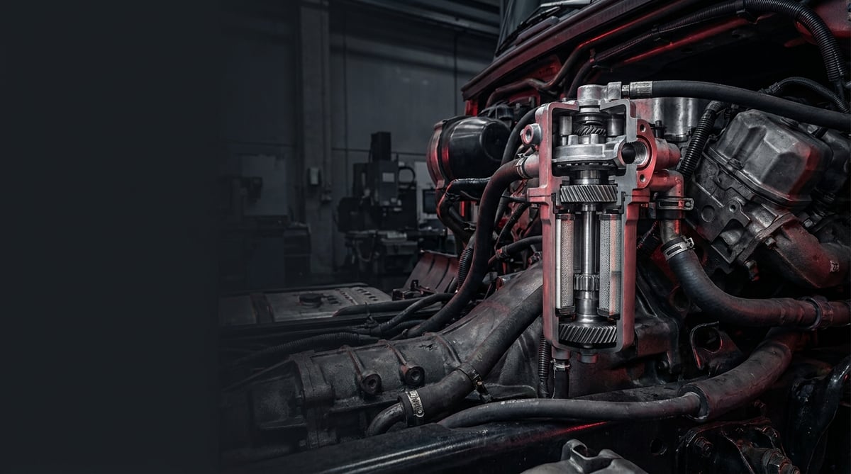
The oil separator works so quietly on heavy commercial engines that nobody notices it — until oil shows up at the turbo inlet, the air filter housing gets oily, or the crankcase ventilation keeps spraying oil. In the field, most technicians who see these symptoms first question the turbo, then the piston rings; yet the real culprit is very often a clogged or torn crankcase ventilation oil separator. On modern EURO 5/6 engines, crankcase gases are no longer released to the atmosphere — they are routed back to the intake through a closed circuit (CCV), and the part that separates the oil vapor from these gases is the oil separator. When the separator fails to do its job, oil enters through the intake line, coats the intercooler, contaminates the EGR and turbo, and increases oil consumption. This guide looks at the engine crankcase ventilation oil separator (static coalescing and centrifugal types) through a field service lens: how it works, what each symptom actually means, how it is replaced, and which inspection point must never be skipped.
E-E-A-T note: This document was prepared by the VADEN ORIGINAL technical team, drawing on heavy commercial vehicle field service experience and OE manufacturer documentation. The figures given here are typical ranges; for exact values such as pressure, temperature and torque, always refer to the vehicle's own current OE service manual. Last updated: September 2026.
Component sizing is based on the relevant international standard family (ISO/EN/DIN/SAE) and the manufacturer OE specification.What Is an Oil Separator? Function and Working Principle
An oil separator is a separation element (crankcase ventilation / CCV oil separator) that removes the oil vapor and oil droplets from the blow-by gases accumulating in the engine crankcase, returns the oil to the crankcase, and sends the cleaned gas to the intake line.
At the root of the working principle lies the blow-by phenomenon. During combustion, some of the pressurized gases in the cylinder slip past the piston rings and escape into the crankcase cavity. This gas is hot, carries combustion products and — most importantly — a fine oil mist. If this gas accumulating in the crankcase is not evacuated, internal pressure rises and the seals and gasket surfaces start to leak oil. This is exactly where the oil separator steps in: it lets the gas pass through, captures the oil inside it and drains it back to the crankcase through a return channel, and directs the remaining clean gas to the intake manifold (closed circuit) or, in some older/open systems, to the atmosphere.
Oil is separated from the gas by two basic methods. Static separators pass the gas through labyrinth channels and a coalescing (merging) fiber/mesh layer, causing the oil particles to collide, merge, grow heavier and drip off; they have no moving parts. Centrifugal separators, on the other hand, use a rotor driven by oil pressure; centrifugal force flings the heavy oil particles onto the rotor wall, where the merged oil returns to the crankcase. Both types are common in heavy commercial applications; the centrifugal type (Alfdex type / equivalent) offers higher efficiency with very fine oil mist.
- Separator body / housing: The part that holds the gas inlet-outlet and the separation element, usually mounted on the valve cover or on the side of the block.
- Coalescing element / filter cartridge (static type): The fiber/mesh layer that merges the oil particles; replaced when it becomes dirty or clogged.
- Centrifugal rotor (centrifugal type): The moving core driven by oil pressure or gear drive that flings the oil out by centrifugal force.
- Pressure regulation (PCV) diaphragm / valve: The spring-loaded diaphragm that balances crankcase pressure and the flow rate of gas returning to the intake, and limits excessive vacuum.
- Oil return (drain) channel and check valve: The line that returns the separated oil to the crankcase and prevents backflow.
- Gasket / O-ring set and heater (in some applications): The sealing element and the heating resistor that prevents freezing/icing in cold climates.
The Difference Between Static (Coalescing) and Centrifugal Separators
Both serve the same purpose, but their characters differ. The static coalescing separator is simple and inexpensive, and since it has no moving parts it rarely suffers mechanical failures; however, its element clogs over time and requires periodic replacement. The centrifugal separator can separate even very fine oil mist, and since it has no element (it is self-cleaning) its maintenance interval is long; on the other hand, it has mechanical components such as a rotor bearing, drive and oil feed, and when they fail it stops spinning. Another difference: when the static type clogs, crankcase pressure rises; when the centrifugal type stops, separation efficiency drops but gas flow continues, which is why its failure is more insidious.
Closed Circuit (CCV) vs. Open Circuit Ventilation
On older engines, crankcase gas was released outside through a hose, onto the road (open circuit); this meant both environmental pollution and oil loss. With EURO 5/6 and modern emission regulations, the system was closed off: the cleaned gas returns to the intake (closed circuit). In a closed circuit, the efficiency of the oil separator directly affects the health of the turbo, intercooler and EGR; a poorly separating separator coats the entire intake line with an oil film. That is why, in CCV systems, the oil separator is no longer "an optional accessory" but a critical part for emissions and engine life.
Its Relationship with the Intake Line and Turbo
The cleaned gas is mostly delivered before the turbo inlet, to the low-pressure intake region. The balance here is delicate: if the separator does not separate well, oil reaches the turbo blades and coats the intake side over time; if the PCV valve creates excessive vacuum, it pulls the seals inward and oil consumption rises; if the line clogs, crankcase pressure rises and forces the seals outward. In other words, oil separator failure rarely appears on its own; it often emerges as the true source of a turbo oiling, oil consumption or seal leak complaint.
| Application / System | Typical Separator Type | Prominent Characteristic | Critical Risk |
|---|---|---|---|
| Heavy commercial diesel (12-13 L, EURO 5/6, closed circuit) | Centrifugal rotor (Alfdex type / equivalent) or coalescing cartridge | High blow-by flow rate, fine oil mist | Oil escape to the intake, turbo/EGR contamination |
| Mid-segment truck / bus (EURO 5/6) | Coalescing element integrated into the valve cover | Medium flow rate, periodic element replacement | Element clogging - rise in crankcase pressure |
| Older / open circuit engines | Labyrinth-type static separator + drain hose | Simple, drained to the atmosphere | Hose clogging, oil dripping |
| Cold climate applications | Heated (resistor) separator / PCV module | Heating against the risk of icing | Heater failure - freezing at the drain, pressure lock |
| High-mileage / worn engine | High flow-rate version of the current type | Increased blow-by, excessive oil mist | Early saturation of the separator, rapid clogging |
Part number verification is essential. Even within the same engine family, the emission level (EURO 5 / EURO 6), separator type (static/centrifugal), PCV valve calibration, heater option and production date change the part. Even though the external appearance is almost identical, the diaphragm spring, drain check valve and flange hole may differ — a PCV with the wrong calibration mismanages crankcase pressure and leads to seal leakage. Before ordering, match by chassis number (VIN) and OE part number; do not decide based solely on the "same engine" information.
Failure Symptoms and Diagnosis
Oil separator failures fall into two groups: clogging / pressure problem (element full, line blocked, PCV stuck) and loss of separation efficiency (torn element, stopped centrifugal rotor, damaged diaphragm). The first raises crankcase pressure and stresses the seals; the second lets oil escape to the intake and increases oil consumption and turbo contamination. Both often look like "another fault" — which is why correct diagnosis is critical.
| Symptom | Possible Cause | Check / Verification |
|---|---|---|
| Oil leaking from the dipstick tube/seals, dipstick popping out of its seat | Crankcase pressure has risen: separator element clogged or ventilation line blocked | Measure crankcase pressure with a manometer/manometric test gauge (at idle and under load). If pressure is felt when loosening the oil filler cap, the ventilation is blocked. |
| Oil accumulation in the air filter housing, intake hose or intercooler | Low separation efficiency: coalescing element torn, centrifugal rotor not spinning | Remove the intake hose and look for an oil film/deposit on the inner wall. On the centrifugal type, check by listening/by hand whether the rotor is spinning (a spinning sound that decreases as soon as the engine stops is normal). |
| Oil consumption has increased but there is no visible external leak and no blue/grey exhaust smoke | Oil is being burned through the intake: separator efficiency is low or the PCV creates excessive vacuum | Record the oil level drop against mileage. Inspect the intake side for oil; to distinguish it from the piston rings/valve stem seals, perform a cylinder leak-down test. |
| Dense vapor/smoke gushing from the oil filler cap, the cap "breathing in and out" | Excessive blow-by + clogged separator; or internal engine wear saturating the separator | Observe the amount of smoke with the cap open. If excessive, first measure crankcase pressure; if high, investigate separator/line clogging, if normal, investigate internal engine wear. |
| Whistling/suction noise from the PCV/separator area, roughness at idle | Diaphragm torn or gasket leaking: false air is being drawn in | Listen to the area; if there is a whistling sound, it is a false air leak. Find the leak point with a smoke/spray test (using a safe, non-flammable method). |
| Ventilation freezes in cold weather, pressure problem on short drives | Heater faulty or drain line iced up: oil/water vapor freezes and blocks the line | On heated models, measure the resistor's resistance and its supply. Detach the drain line and look for ice/sludge clogging. |
| Abnormal vibration, metallic noise in the centrifugal separator | Rotor bearing worn or rotor imbalance (deposit/damage) | Isolate the noise while the engine is running. Remove the rotor and check its free rotation, its play, and the balance of the deposit inside it. |
| The same symptoms returning a short time after replacement | Root cause unsolved: excessive blow-by (piston ring/liner wear) is rapidly saturating the separator | Measure crankcase pressure and blow-by flow rate; if abnormally high, the problem is not in the separator but inside the engine. Perform a leak-down / compression test. |
Quick Differentiation with Crankcase Pressure Measurement
The single most decisive measurement in oil separator diagnosis is crankcase pressure. With a suitable manometer/blow-by test gauge, measure crankcase pressure at idle and under load. If pressure is higher than normal (ventilation blocked), the problem is in the separator element, the line, or a stuck PCV. If pressure is normal but there is oil in the intake, look for the problem in separation efficiency (torn element, stopped rotor). If pressure is excessively high and the blow-by flow rate is also high, the real root cause is internal engine wear; in this case, replacing only the separator brings the fault back in a short time.
Distinguishing Intake Oiling from the Piston Ring/Valve Stem Seal
This is the diagnosis most often confused in the field. When oil is seen in the intake line, the turbo or piston rings are immediately blamed; yet a torn coalescing element or a stopped centrifugal rotor creates exactly the same oiling. The clean way to distinguish: inspect the clean gas line at the separator outlet — if there is oil here, the culprit is the separator. In addition, if the cylinder leak-down test shows abnormal blow-by together with blue smoke, it is internal engine wear; if blow-by is normal but there is oil in the intake, the separator is responsible.
Verifying That the Centrifugal Rotor Is Spinning
On a centrifugal separator, the most critical question is whether the rotor is spinning. The moment you stop the engine, a spinning rotor continues to spin freely for a while and slows to a stop; you can confirm the rotation by listening to this sound. If there is no sound at all, or the rotor stops instantly, there may be a bearing/drive failure or an oil feed problem. When you remove the rotor, it should spin freely by hand and without play; if it binds, catches or has excessive play, it must be replaced.
Further reading
For a plain-language technical overview of this subject, see the reference article on Wikipedia. Always confirm specific figures and procedures against the vehicle manufacturer service data.
Replacement / Installation Steps
Personal protective equipment and safety: Do not work on a hot engine; the separator and ventilation lines can be hot and pressurized with combustion products. Wait until the engine cools to a hand-touchable temperature. Oil-resistant gloves, safety glasses and work clothing are mandatory; crankcase gas and oil vapor are harmful, so work in a well-ventilated environment. The vehicle must be on level ground, with the parking brake applied and chocked. Disconnect the battery negative terminal (especially on heated/sensored PCV modules). Collect the removed oily elements and dirty oil according to waste regulations — do not pour them on the ground or into a drain.
- Verify and record the fault: Before replacement, prove that the problem really is in the separator by measuring crankcase pressure and blow-by. Note the fault codes, the oil consumption record and the intake line observation; these records will help you during the warranty and part return process.
- Match the correct part by VIN: Before removal, have the new separator/cartridge and the gasket and O-ring set ready. Physically compare the separator type (static/centrifugal), PCV calibration, heater option and flange arrangement against the old part. If single-use bolts are specified, use new ones.
- Open the access path: Depending on the separator's location, remove obstacles such as the engine top cover, intake hoses, wiring harness duct or fuel lines. Label every hose and connector you remove; on heavy commercial vehicles, the similar-looking ventilation and intake lines are frequently confused.
- Detach the ventilation and drain lines: Remove the clean gas outlet hose and the oil return (drain) line. Drain the oil accumulated inside them into a clean container; if there is sludge/sediment in the drain line, record it — it is a root cause clue. Cap the open ports with a clean plug/cloth.
- Remove and inspect the old separator: Loosen the bolts crosswise and in stages. Inspect the removed element before discarding it: if there is excessive oil saturation, a torn element, a clogged mesh or deposit/wear on the centrifugal rotor, the root cause of the problem may be internal to the engine (excessive blow-by). Simply replacing the part is not a solution in this case.
- Clean the mating surfaces and channels: Clean the gasket surface with a plastic/soft scraper; do not use a metal scraper or grinding disc — any scratch you leave becomes a leak path on the first heating cycle. Clean and check the drain channel and check valve for clogging; a blocked drain will quickly saturate the new element too.
- Install the new gasket, O-ring and element: Never reuse gaskets. If the manual permits, moisten the O-rings with a thin film of clean oil; do not use grease/sealant unless specified. Position the coalescing element paying attention to its orientation and full seating.
- Seat the separator and torque it: Position the part without forcing; if it binds, it is the wrong part or the wrong angle. Start the bolts by hand first, then tighten them crosswise and in stages with a torque wrench. On plastic-bodied separators, overtightening cracks the body — be sure to observe the specified low torque value.
- Connect the lines and verify the PCV/check valve direction: Connect the clean gas and drain lines to the correct ends as specified. Check the flow direction of the drain check valve — a check valve installed backwards prevents oil from returning to the crankcase and fills the separator.
- Make the heater and sensor connections (if any): On heated/sensored modules, seat the connectors fully and secure the wiring harness against chafing. Reconnect the battery terminal and clear the fault codes.
- Test and verify: Start the engine and check for ventilation leaks and whistling noise at idle. Measure crankcase pressure again — confirm that it has returned to the normal range. On the centrifugal type, verify the rotor rotation by listening. After a short road test, once more check that there is no oiling in the intake line and the oil filler cap area.
Points to Watch (Common Mistakes)
Bypassing the separator or venting the hose to the atmosphere is both prohibited and harmful to the engine. Blanking the oil separator or releasing the ventilation onto the road in a closed circuit system violates emission regulations and disrupts the crankcase pressure balance. Even though in the short term it may look like "the leak stopped," unbalanced crankcase pressure stresses the seals and gaskets and leaves oil consumption uncontrolled. The correct solution is not to bypass the separator but to renew it with the correct part and to investigate the root cause (blow-by).
Skipping the root cause and replacing only the element is an expensive cycle. If the separator element saturates or clogs with oil in a very short time, the real reason is often excessive internal blow-by (worn piston rings/cylinder liner). Renewing only the separator postpones the symptom by a few thousand kilometers but does not solve the problem. If crankcase pressure comes out high, evaluate the engine internals with a leak-down/compression test before replacement.
- Installing the drain check valve backwards: It prevents oil from returning to the crankcase; the separator fills in a short time and lets oil escape to the intake. Always verify the flow direction during installation.
- Overtightening the plastic body: It creates cracks and micro-leaks; observe the specified low torque value and staged tightening.
- Wrong PCV calibration / wrong part: A diaphragm with a different spring pressure changes the crankcase vacuum; excessive vacuum pulls the seals inward, low vacuum raises the pressure.
- Not cleaning the drain line: A blocked return channel will quickly saturate the new element too; always check the line during replacement.
- Cleaning the gasket surface with a metal scraper: Every scratch left behind is a direct oil leak path.
- Neglecting the heater/sensor connector: In cold climates, a drain left without a heater freezes and a pressure lock forms; if the sensor is not connected, a fault code and warning lamp appear.
- Reinstalling the centrifugal rotor unbalanced/dirty: Deposit imbalance creates vibration and bearing wear; clean the rotor's inner surface and verify its free rotation.
- Neglecting the oil change and blaming the separator: Oxidized, water-contaminated oil produces more vapor and clogs the separator early; fluid maintenance directly affects separator life.
Technical Values and Inspection Points
The values below are the typical/general reference ranges encountered in heavy commercial applications, and are intended to guide the "is it normal or not?" question during diagnosis. The engine family, emission level, separator type and PCV calibration can shift these values significantly. For exact values, the vehicle's current OE service manual is authoritative.
| Parameter | Typical Reference Range | Note / Comment |
|---|---|---|
| Crankcase pressure (healthy engine, idle) | approx. 0-10 mbar (slight vacuum ~ 0) | Generally near zero or slight vacuum. Significant positive pressure indicates ventilation clogging. |
| Crankcase pressure (warning threshold, under load) | approx. above 20-40 mbar is suspect | Persistent high value: clogged separator/line or excessive blow-by. Use the threshold in the manual as the basis. |
| PCV intake vacuum (regulated, typical) | limited to approx. 5-25 mbar range | Excessive vacuum pulls the seals inward; the diaphragm/spring limits this. |
| Engine oil normal operating temperature | approx. 90-110 °C | At low temperature, condensation increases and more water/vapor reaches the separator. |
| Acceptable oil consumption (general) | varies by application (manual is authoritative) | A sudden increase signals separator efficiency loss or internal engine wear; refer to the manual for the exact limit. |
| Blow-by flow rate (wear indicator) | depends on the manufacturer/measurement method | High blow-by saturates the separator; the root cause is inside the engine. Use the OE value for reference. |
| Separator element replacement interval (static type) | typically with oil maintenance or at manual mileage | The interval shortens under heavy duty/high mileage. There is no element in the centrifugal type. |
| Heater resistor resistance (heated module) | application-specific (order of a few ohms) | If the measured value deviates from the manual, the heater is faulty; the exact value is vehicle-specific. |
Torque values are as critical as the part itself in separator installation — especially on plastic-bodied parts. The table below shows typical orders of magnitude; the value to be applied must always be taken from the vehicle-specific manual.
| Connection | Typical Torque Order | Application Note |
|---|---|---|
| Separator/PCV module body bolts (M6) | approx. 8-12 Nm | Overtightening on a plastic body cracks it; tighten crosswise and in stages. |
| Separator body bolts (M8) | approx. 18-28 Nm | On a metal body/flange, 2-3 stages in crosswise order are recommended. |
| Centrifugal rotor cover nut | approx. 15-30 Nm (depending on application) | Manual is authoritative for the exact value; do not disturb the rotor play. |
| Ventilation / drain hose clamps | the clamp torque specified by the manufacturer | Full sealing to prevent false air leaks; do not overtighten and crush the hose. |
| Valve cover fastening bolts (integrated separator) | approx. 8-15 Nm | On separators integrated into the cover, the cover torque and sequence are critical. |
Field tip: After installing a new separator, measure crankcase pressure once more within the first 500-1000 km and review the intake line. If the pressure stays in the normal range and the clean gas line stays dry, the job is clean. If the pressure climbs again, the culprit is not the new part but an unsolved root cause (excessive blow-by, clogged drain). During the same period, check the area around the oil filler cap once more.
- Is crankcase pressure in the normal range? (Measure at idle and under load; if significant pressure is felt when loosening the oil filler cap, the ventilation is blocked.)
- Are the intake hose, air filter housing and the inner wall of the intercooler clean of oil?
- Is there oil accumulation in the clean gas (separator outlet) line?
- Are the drain (oil return) line and check valve open and in the correct direction?
- On the centrifugal type, does the rotor spin freely and slow to a stop when the engine stops?
- On a heated module, are the resistor resistance and connector sound?
- Is there a sudden increase in oil consumption or gushing from the dipstick tube?
- At the first check after replacement, does the pressure climb again? (If it climbs, the root cause must be investigated.)
Maintenance and Service Life
The service life of the oil separator varies by type. Static coalescing elements are consumables; the fiber/mesh inside them fills with oil and soot over time and is replaced periodically — in most applications this is planned together with a certain mileage or an oil service. Centrifugal separators do not require element replacement because they are self-cleaning; their life is determined by the bearing, drive and regular internal cleaning. In both types, the real determining factor is how much blow-by the engine produces: on a healthy engine the separator works trouble-free for a long time, while on a worn engine even the highest-quality separator saturates early.
- Do not delay static element replacement: Follow the mileage/maintenance interval given by the manual. A clogged element raises crankcase pressure and stresses the seals; "it still works" is not a criterion.
- Stay faithful to the oil change and OE specification: Oxidized, water-contaminated oil produces more vapor and saturates the separator early. Fluid discipline is directly separator life.
- Check the drain line periodically: A blocked return channel will fill even a sound separator; verify its clearance at every service.
- Clean the centrifugal rotor at the recommended interval: Although it is self-cleaning, heavy deposit on the inner surface creates imbalance and bearing wear; carry out the inspection/cleaning prescribed by the manual.
- Monitor the effect of short drives and cold climate: On vehicles where the engine does not warm up enough, condensation and emulsion quickly foul the separator; on heated modules, check the heater's health.
- Track crankcase pressure: On fleet vehicles, periodic pressure measurement catches both separator clogging and increasing engine wear early.
- Do not overlook the intake line: Oiling at the intercooler and turbo inlet is the earliest visible sign of separator efficiency loss.
- Do not skip the first check after replacement: A pressure and leak check after the first 500-1000 km catches problems arising from installation or root cause while they are still cheap.
In short: oil separator maintenance is actually about keeping the entire crankcase ventilation healthy. A fleet that changes the correct oil on time, keeps the drain line open and periodically monitors crankcase pressure mostly closes out oil separator failures with a small element or gasket change. When neglected, the same part turns into a much more expensive bill in the form of turbo oiling, seal leakage and increased oil consumption. The difference is the difference between one maintenance item and a series of consecutive failures.
The VADEN ORIGINAL oil separator product family is offered from stock for heavy commercial vehicle crankcase ventilation (CCV) applications, with a body true to OE dimensions, correct PCV calibration, a coalescing element or centrifugal rotor structure and a complete gasket set. To verify the oil separator suitable for your vehicle by chassis number and OE part number, to see the scope of our product family, or to get technical confirmation before installation, you can review the oil separator group in the VADEN ORIGINAL catalog or contact our technical team.
Related categories: Oil Separator Filter
Related technical guides: Exhaust Manifold: Cracks, Leaks, Replacement & Torque Guide · Engine Cylinder Head Group: Faults, Replacement & Maintenance · Exhaust / Engine Brake: Faults, Replacement & Maintenance Guide · Oil Cooler: Failure Symptoms, Replacement & Maintenance Guide · Truck Oil Pan Group: Faults, Replacement & Maintenance Guide
Application and compatibility: Vehicle compatibility catalogue · Engine compatibility catalogue
Main guide: Low Engine Oil Pressure: Symptoms, Causes, and the Role of the Oil Pump
Tags
Frequently Asked Questions
- How do you tell if the oil separator has failed?
- The clearest signs: oil leaking from the dipstick tube/seals and dense vapor from the oil filler cap (rising crankcase pressure), oil accumulation in the air filter housing/intake hose/intercooler (falling separation efficiency), and an increase in oil consumption without any external leak. If one of these symptoms is present, verify by measuring crankcase pressure before replacing the part.
- What does the oil separator do?
- It separates the oil vapor within the blow-by gases accumulating in the engine crankcase from the gas; it returns the captured oil to the crankcase and sends the cleaned gas to the intake line. This both balances crankcase pressure and prevents oil escape to the intake line, the turbo and the EGR. On closed circuit (CCV) engines, it is a critical part for emissions and engine life.
- There is oil in the intake line/intercooler — is it definitely the turbo?
- No — and this is the most costly assumption in the field. A torn coalescing element or a stopped centrifugal rotor creates exactly the same oiling. To distinguish, inspect the clean gas line at the separator outlet: if there is oil here, the culprit is the separator. Before blaming the turbo seal, always check the separator and crankcase pressure.
- Can the oil separator be bypassed?
- Technically the vehicle will run, but it is both inadvisable and, on closed circuit systems, against regulations. Blanking the separator disrupts the crankcase pressure balance, stresses the seals and leaves oil consumption uncontrolled. The correct solution is not bypassing but renewing with the correct part and, if necessary, investigating the root cause (excessive blow-by).
- When should the oil separator be replaced?
- On the static coalescing type, the element is a consumable and is usually replaced together with the mileage or oil service given by the manual; the interval shortens under heavy duty and high mileage. On the centrifugal type there is no element, and maintenance is limited to rotor inspection and internal cleaning. If there is a symptom (high crankcase pressure, intake oiling), an evaluation is made without waiting for the interval.
- What is the difference between a static and a centrifugal oil separator?
- The static (coalescing) type captures oil with a labyrinth and fiber layer; it has no moving parts and is simple, but its element is replaced periodically and crankcase pressure rises when it clogs. The centrifugal type uses centrifugal force with a spinning rotor; it separates even very fine oil mist and is self-cleaning, but it has mechanical components such as a bearing/drive, and when it stops, separation efficiency drops insidiously.
- I installed a new separator but crankcase pressure is still high — why?
- The first suspect is a clogged drain (oil return) line or a check valve installed backwards; the separator cannot return the oil to the crankcase and fills up. The second is that the root cause was never solved: a worn engine producing excessive blow-by saturates even the best separator. Evaluating the engine internals with a leak-down/compression test before installing a new part prevents this situation from the outset.
- How do I choose the correct oil separator?
- Match by chassis number (VIN) and OE part number. Even within the same engine family, the emission level, separator type (static/centrifugal), PCV calibration, heater option and production date change the part; two parts may look almost identical from the outside while the diaphragm spring and drain check valve differ. Confirming the part number with the technical team before ordering is much cheaper than bringing the vehicle down a second time because of the wrong part.
- How can I check whether the centrifugal rotor is still spinning?
- Listen the moment you shut the engine down: a sound rotor keeps spinning freely for a while and slows to a stop, and that sound confirms rotation. No sound at all, or an instant stop, points to a bearing or drive failure or an oil feed problem. With the rotor removed, it should turn freely by hand without play; if it binds, catches or has excessive play, replace it.
- How do short trips and cold weather affect the oil separator?
- On vehicles where the engine never warms up properly, condensation and emulsion foul the separator quickly and the element saturates early. On heated modules, a failed heater lets the drain line freeze and a pressure lock forms; an unconnected sensor sets a fault code and warning lamp. Check heater health and drain line clearance at every service, and keep to the oil change interval.
Related Articles

Brake Caliper Mechanism: Camshaft, Bearings, and Return Spring
Inside the truck air disc brake caliper: how the camshaft, thrust bearings, return spring and automatic adjuster turn push-rod force into pad pressure.
Tachograph Explained: Driver Cards, Symbols, Rest Times
How tachographs work in trucks and buses: analogue, digital and smart types, driver and company cards, symbols, download rules and roadside checks.
ADR Guide: Vehicle & Driver Rules for Dangerous Goods Transport
Learn what ADR means for heavy trucks: hazard classes, required vehicle equipment, driver certification, orange plate labeling, and inspection documents.


