Brake Caliper Mechanism: Camshaft, Bearings, and Return Spring
Inside the truck air disc brake caliper: how the camshaft, thrust bearings, return spring and automatic adjuster turn push-rod force into pad pressure.

In the workshop, a tractor unit's rear axle is raised and the wheel is turned by hand. A light drag on the disc is normal, but this one is different: the wheel gives a faint "tick" at the same point on every rotation. On another vehicle the symptom is the opposite — the brake pedal is released, yet the pad will not release from the disc, and within a few kilometres the rim is too hot to touch. Neither symptom originates in the caliper housing itself; both trace back to a hidden mechanism inside it: the camshaft, its bearings, the return spring, and the adjuster gear assembly. Together these four components turn the straight-line push from the brake chamber into the force that clamps the pad against the disc. This guide covers that internal mechanism of the air disc brake caliper from end to end — how it works, how it fails, and how it is replaced.
What is the caliper mechanism? Function and operating principle
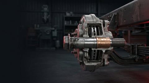
The caliper mechanism is the internal assembly of an air disc brake that converts the linear push force from the brake chamber into the force that clamps the pad against the disc. It consists of the camshaft (eccentric shaft), the bearings that support it, the return spring that pulls the assembly back to its starting position when the brake is released, and the adjuster gear assembly that automatically keeps the running clearance constant as the pad wears. Together, these four components let the caliper generate braking force consistently and predictably.
The force chain works as follows: when the brake pedal is pressed, air pressure is applied to the chamber, and the chamber's pushrod is connected to a lever that projects outside the caliper. This lever transmits a rotating motion to the camshaft inside the caliper housing. As the eccentric profile on the camshaft rotates, it displaces the bridge plate seated on it linearly toward the disc. The bridge pushes the tappets connected to the adjuster gear assembly; the inner pad contacts the disc first, and the resulting reaction force slides the caliper housing along its guide pins so that the outer pad is also pressed against the disc. The result is that a single chamber stroke clamps both pads against the disc with equal force.
The mechanism's second function is leverage: the geometry of the crank arm amplifies the comparatively modest force from the chamber before it reaches the pad. Its third function is repeatability — the caliper mechanism has to maintain the same clearance and the same force-travel relationship over thousands of brake applications; otherwise pedal feel changes, brake response time lengthens, or the pad wears prematurely.
How does the camshaft (eccentric shaft) work?
The camshaft is a steel shaft positioned on a horizontal axis inside the caliper housing, with one end receiving the rotating motion from the chamber lever. It carries an eccentric or cam profile offset from its centre line; as the shaft rotates, this profile pushes the bridge plate, converting rotary motion into linear motion. The camshaft's rotation angle is limited — not a full revolution, but a few degrees are enough to bring the pad into contact with the disc. This small angle allows both fast response and precise force control.
Why are the bearings (thrust bearings) needed?
Bearings or slide bushings sit at both ends of the camshaft and on the surfaces where the bridge plate slides inside the housing; needle bearings are the common solution in heavy-duty calipers. The bearings' job is to minimise friction — the lower the friction, the greater the share of the chamber's force that reaches the pad, and the smaller the share converted into heat. The bearings also keep the camshaft centred on its axis; once they wear, radial play develops in the shaft, which makes the bridge tilt and causes uneven pad wear.
What does the return spring do?
When the brake pedal is released, air pressure in the chamber drops, but a separate force is still needed to return the camshaft and bridge plate to their starting position — this is the return spring's job. The spring guarantees that a narrow but measurable running clearance forms between the pad and the disc. Without this clearance, the pad would stay in constant contact with the disc; a dragging pad heats up, increases fuel consumption, and wears out prematurely.
How does the adjuster gear assembly (automatic adjuster mechanism) work?
The pad wears a tiny amount with every brake application; if this wear is not compensated, the running clearance gradually grows, pedal travel lengthens, and brake response is delayed. The adjuster gear assembly is a clutch-gear or worm gear mechanism integrated into the camshaft; whenever the running clearance exceeds the defined limit during a brake application, the mechanism advances one increment, turning the adjusting screw and keeping the pad-to-disc clearance constant. This automatic adjustment means the driver feels the same pedal travel and the same brake response throughout the pad's service life, eliminating the need for manual adjustment.
| Component | Function | Symptom when worn |
|---|---|---|
| Camshaft (eccentric shaft) | Transmits rotating motion from the chamber to the bridge as a linear push | Wear on the eccentric profile, uneven pad pressure |
| Thrust bearings | Support the camshaft and bridge with low friction | Radial play, ticking/knocking noise, increased heat |
| Bridge plate | Transfers motion received from the camshaft to the adjuster gear assembly | Tilted seating, one-sided pad wear |
| Return spring | Returns the assembly to its starting position when the brake is released | Pad dragging, constant light contact |
| Adjuster gear assembly | Automatically keeps running clearance constant as the pad wears | Longer pedal travel, delayed brake response |
| Dust boots / seals | Protect the camshaft and bridge from dirt, moisture, and salt | Internal corrosion, mechanism sticking |
What is the difference between the caliper mechanism and the drum brake slack adjuster?
In drum brakes, automatic adjustment is performed by a separate external arm mechanism (the slack adjuster); the chamber's pushrod moves this arm from outside, and the arm can be observed visually. In disc brakes, by contrast, the adjuster mechanism is a sealed gear-clutch system inside the caliper housing, integrated into the camshaft — it is not visible from outside and cannot be observed directly without removing the caliper. This difference also changes the diagnostic method: on a drum brake the arm's movement angle is checked visually or by measurement, while on a disc brake diagnosis is done indirectly, through brake pedal travel, the play felt when the wheel is turned by hand, and pad thickness measurement.
Standards and further reading
This subject is governed by the equipment rules for air-braked commercial vehicles. In the United States the federal air brake standard, FMVSS 121 (49 CFR 571.121) defines the reservoirs, protection and timing a compliant system must provide, and Europe applies the equivalent limits of UNECE Regulation No. 13. For further detail, see the illustrated reference guide at airbrakecompressor.com. Always confirm specific figures against the current regulation and the vehicle manufacturer service data.
Outside the United States the equivalent duties sit in national law. In the United Kingdom, regulation 18 of the Road Vehicles (Construction and Use) Regulations 1986 requires every part of the braking system to be maintained in good working order. In Canada, air brake systems fall under the Motor Vehicle Safety Regulations, which contain CMVSS 121.
How is a caliper mechanism fault recognised?
A caliper mechanism fault is often mistaken for a simple pad problem, because the first symptom usually shows up on the pad — uneven wear, dragging, or squealing. But if the same symptom returns after the pad has been renewed, the problem lies in the mechanism itself. The main symptoms encountered in the field and how to check for them are as follows:
| Symptom | Probable cause | Check / verification |
|---|---|---|
| Disc/rim gets excessively hot after braking, pad is dragging | Return spring broken or weakened, or the adjuster gear assembly has over-advanced | Turn the wheel by hand and feel for constant drag, visually inspect the spring |
| Rhythmic ticking/knocking noise during braking or wheel rotation | Wear and radial play in the camshaft bearings | Without removing the caliper, grip the bridge by hand and check for radial play |
| Brake pedal becomes stiffer over time or travel lengthens | Adjuster gear assembly is not tracking pad wear, mechanism is sticking | Measure the pad-to-disc running clearance, test the freedom of movement of the adjuster mechanism |
| Vehicle pulls to one side under braking | One of the two calipers on an axle produces less force than the other | Compare the pad contact pattern and colour uniformity of both calipers on the same axle |
| Visible play in the bridge plate, guide bolts loose | Play has grown in the bridge axis due to bearing wear | Push the bridge by hand and check the amount of free play |
| Pad wears unevenly, one edge noticeably thinner than the other | Camshaft or bridge is moving at an angle, bearing wear is asymmetric | Compare pad thickness at both ends with a micrometre or caliper gauge |
| No advancing sound/feel from the adjuster mechanism | Adjuster gear assembly has rusted or become fouled and is seized | Turn the adjuster mechanism by hand with a suitable tool and check for resistance and a clicking feel |
How is play (clearance) in the caliper mechanism checked?
The check begins with the wheel on the ground: the park brake is released, the wheel is turned by hand, and an even, light drag is expected throughout the full rotation. A noticeably increased resistance at one point, or a periodic "tick" felt, points to a fault in the camshaft bearings or the bridge seating surface. The second step is a manual check of the bridge plate; light sideways force is applied to the bridge, either through the dust boot or with the caliper open, and any perceptible play indicates that bearing clearance has grown.
The third step is measuring the pad-to-disc running clearance; this measurement shows whether the adjuster gear assembly is doing its job. If the clearance is above the vehicle's defined range, the adjuster mechanism is not advancing — usually because of corrosion, fouling, or gear wear. If there is no clearance, or the pad is in constant light contact, the return spring or an over-advanced adjuster mechanism should be investigated. In both cases, the final diagnosis is confirmed only by removing the caliper and visually inspecting the mechanism.
The drag felt at the wheel does not always come from the mechanism; to check separately whether the caliper still slides freely on its carrier, see the caliper guide pin, bushing and bolt guide.
How is the caliper mechanism replaced? Step by step
- Park the vehicle on level, solid ground, apply the park brake, place wheel chocks, and switch off the engine.
- Release the air pressure on the relevant axle according to the system instructions; the chamber or air line connection must never be loosened before pressure has been vented.
- Remove the wheel, take out the pads, and detach the caliper from the carrier; support the caliper so that hoses and cables are not left under tension.
- Disconnect the brake chamber from the caliper and move the caliper housing to the workbench.
- Remove the dust boots and seals; carefully take the bridge plate and the adjuster gear assembly out of the housing.
- Remove the camshaft together with its bearings from the housing; take care that the bearing needles or rollers are not lost during removal.
- Clean the inner surfaces of the housing, the camshaft bearing seat, and the bridge sliding surfaces; remove old grease and wear debris, and visually inspect the eccentric profile and bearing surfaces for signs of wear.
- Lubricate the repair kit — containing the new camshaft, bearings, return spring, and adjuster gear assembly — with the high-temperature assembly grease specified by the manufacturer.
- Fit the components in the reverse order of removal: camshaft, bearings, bridge plate, adjuster gear assembly, return spring, then the dust boots and seals.
- Seat the caliper on the carrier, grease the guide pins, and tighten the bolts in a crosswise, staged sequence; torque values must be taken from the vehicle's current OE service manual.
- Connect the chamber, fit the pads, mount the wheel, restore air pressure, and press the brake pedal a few times to confirm that the adjuster gear assembly automatically sets the running clearance and that the wheel turns freely.
Points of caution: common mistakes
- Trying to replace bearings one at a time: The caliper mechanism is designed as a set; replacing a single part leads to dimensional and tolerance mismatches.
- Fitting new pads without resetting the adjuster mechanism: The running clearance is left uncalculated, and on first use the pedal feels either too stiff or too soft.
- Using the wrong type of grease: Grease not rated for high temperature melts or runs out quickly; the bearing is left dry and wears rapidly.
- Reusing the dust boot or seal: A torn or hardened boot lets in moisture and dirt, accelerating corrosion inside the mechanism.
- Tightening the guide bolts to full torque in one go: Without a crosswise, staged tightening sequence, the bridge seats at an angle and the pad wears unevenly.
- Forcing the camshaft into place with a hammer: Impact permanently damages the eccentric profile and the bearing seat; the shaft must always be seated by hand or with a suitable tool.
- Choosing a part by brand: The correct repair kit is selected using the OE reference number stamped on the caliper and the vehicle's engine/chassis code, not by brand name.
- Starting disassembly before pressure is vented: Uncontrolled release of an air- or spring-loaded component can cause serious injury.
Technical values and check points
The table below summarises the main points checked in the field on the caliper mechanism and their general reference ranges. Values vary by vehicle manufacturer, caliper model, and system; the exact value must always be taken from the vehicle's current OE service manual.
| Check point | General reference | What deviation indicates |
|---|---|---|
| Pad-to-disc running clearance | A narrow gap with no perceptible drag when the brake is released (OE value is authoritative) | Too large lengthens pedal travel; too small or absent causes dragging |
| Camshaft radial play | Too small to be felt by hand (OE tolerance is authoritative) | Perceptible play indicates worn bearings |
| Adjuster gear assembly advancing behaviour | Small, incremental advance whenever needed on each brake application | No advance indicates the mechanism is sticking or seized |
| Return spring tension | Force sufficient to return the bridge and camshaft fully to their starting position | If weak, the pad continues to contact the disc |
| Guide pin / bridge bolt torque | Value defined in the vehicle's OE service manual, crosswise staged tightening | Too low causes loosening and vibration; too high causes housing deformation |
| Assembly grease type | Manufacturer-approved special grease resistant to high temperature and water | Wrong grease causes premature drying out or running |
| Dust boot / seal integrity | No tears, fully seated in place | If torn, dirt and moisture enter and internal corrosion begins |
| Pad wear symmetry | Similar thickness between the two pads and between both ends of each pad | A large difference indicates the mechanism is running tilted or unbalanced |
Caliper mechanism maintenance and service life
The single strongest factor determining the caliper mechanism's service life is the integrity of the dust boots and seals. During periodic maintenance, dust boots should be visually checked for tears, hardening, or poor seating, and fouled boots should be replaced; moisture and salt that get inside the mechanism corrode the camshaft and bearings within a short time. Every time the pads are changed, the freedom of movement of the adjuster gear assembly and the tension of the return spring should also be checked — these two components are not replaced as often as the pads, but they should be checked just as often.
High-pressure washing is a particular risk for the caliper mechanism. When a water jet is aimed directly at the dust boot or the bridge area, water can enter past the boot's edge; this is not apparent at the time, and shows up days later as corrosion and stiffness. For fleets operating in salty, wet winter road conditions, periodically checking the caliper mechanism visually and by hand without removal — bridge play, adjuster mechanism resistance, spring tension — is the cheapest way to catch a fault before it causes a breakdown on the road.
Fleet operators are advised to add a caliper mechanism check alongside pad thickness measurement in their periodic maintenance plan. Sticking in the adjuster gear assembly or early bearing wear can begin even while the pad is still above its limit value; catching these early signs significantly reduces the risk of sudden pad dragging or one-sided brake loss out on the road.
VADEN ORIGINAL caliper mechanism components
VADEN ORIGINAL manufactures camshafts, bearing sets, return springs, adjuster gear assemblies, and the complete repair kits that combine them, to OE dimensions and tolerances, for heavy commercial vehicle air disc brake calipers. The product range covers the caliper housing types and mounting geometries commonly used in truck, tractor unit, bus, and trailer applications.
To find the correct repair kit, using the OE reference number on the caliper housing and the vehicle's engine/chassis code, rather than the vehicle's make and model, removes the risk of a wrong match. The caliper mechanism is the final link — and the one that actually generates braking force — in a chain that starts with the compressor drying the air in the brake system; if an earlier link in that chain (air dryer, relay valve, brake chamber) has a problem, brake performance is affected even if the caliper mechanism itself is sound. The VADEN technical guide library includes separate fault, replacement, and maintenance guides for the air compressor, air dryer, relay valve, brake chamber, ABS sensor, and brake pad.
Related categories: Bearing · Crankshaft · Spring · Bolt · Cover
If you also want to weigh the sourcing side of part selection, such as catalogue accuracy and production consistency, the article on choosing aftermarket truck brake components complements this view.
Main guide: Air Disc Brake Caliper: Faults, Replacement & Maintenance Guide
Tags
Frequently Asked Questions
- What is the caliper mechanism, and what parts does it consist of?
- The caliper mechanism is the assembly inside the housing of an air disc brake caliper that transfers force from the chamber to the pad. It consists of the camshaft (eccentric shaft), the bearings that support it, the bridge plate, the return spring, and the adjuster gear assembly that automatically compensates for pad wear.
- Can the vehicle still be used if the caliper mechanism fails?
- The vehicle can usually still be stopped, since the brakes on the other axles keep working, but braking force on the affected axle is reduced, or the pad drags continuously. Because this can lead to pulling to one side under braking, a risk of instability, and overheating, the vehicle should be inspected promptly, and speed and following distance should be treated with caution until the fault is fixed.
- What can cause the pad to drag (rub continuously)?
- The most common causes are a broken or weakened return spring, an adjuster gear assembly that has advanced further than it should, or a bridge plate sticking due to rust on its guide surfaces. When dragging is noticed, the wheel should be turned by hand to confirm the drag, and the caliper should be checked promptly.
- How is the adjuster gear assembly (automatic adjuster) tested?
- The definitive test requires removing the caliper and visually inspecting the mechanism; an indirect indicator in the field, however, is measuring the pad-to-disc running clearance. If the clearance is above the defined range, the adjuster mechanism is not tracking pad wear; this is usually caused by the mechanism becoming fouled or rusted.
- How often are camshaft bearings replaced?
- There is no fixed mileage or time interval defined for the bearings; the caliper repair kit is generally renewed as a whole together with the pads. The main factors that shorten its life are moisture and dirt entering through a torn dust boot, the use of the wrong grease, and high-pressure washing aimed directly at the boot area.
- Are replacing the caliper mechanism and replacing the pads the same job?
- No, they are not. Replacing the pads means opening the caliper and renewing the worn friction material; replacing the caliper mechanism requires removing and renewing the camshaft, bearings, spring, and adjuster gear assembly inside the housing, and is a much more extensive job. Whenever the pads are replaced, the freedom of the mechanism and the return spring's tension must always be checked.
- Does a ticking noise always indicate a bearing fault?
- No. A periodic ticking noise mostly points to radial play in the camshaft bearings, but loose guide pins, worn dust boot retainers, or a tilted seating of the bridge plate can produce similar noises. The exact source is determined only by removing the caliper and checking each component individually.
- Should a repair kit be bought, or a single part?
- Manufacturers generally supply the camshaft, bearing set, return spring, and adjuster gear assembly as a single repair kit; the components are dimensioned relative to each other. Replacing a single part alone (for example, just the bearing) can cause a tolerance mismatch with the other components, so the complete kit should be preferred.
- What happens if the return spring breaks?
- When the spring breaks, the bridge plate and camshaft cannot fully return to their starting position after braking, and the pad remains in light contact with the disc. This shows up as dragging, overheating, increased fuel consumption, and premature pad wear; once noticed, the caliper mechanism should be checked.
- What should I pay attention to when choosing a caliper mechanism?
- The only reliable basis for selection is the OE reference number on the caliper housing. Beyond that, the vehicle's engine and chassis code, the caliper housing type, and the mounting geometry are decisive. Choosing by reference number rather than brand name prevents faults caused by geometric or tolerance mismatches.
Related Articles
Caliper Guide Pin, Bushing & Bolt: Faults, Repair, Care
Learn how caliper guide pins and bushings seize, how to diagnose uneven pad wear, and the correct removal, greasing and torque steps for replacement.

Tachograph Explained: Driver Cards, Symbols, Rest Times
How tachographs work in trucks and buses: analogue, digital and smart types, driver and company cards, symbols, download rules and roadside checks.
ADR Guide: Vehicle & Driver Rules for Dangerous Goods Transport
Learn what ADR means for heavy trucks: hazard classes, required vehicle equipment, driver certification, orange plate labeling, and inspection documents.


