Oil Spray Jet: Faults, Replacement and Maintenance Guide
Engine oil spray jet guide for trucks: how piston cooling nozzles work, clogging and low oil pressure symptoms, diagnosis, replacement steps and torque values.
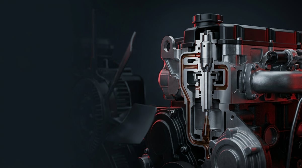
It is one of the first things a technician looks at once an engine is opened up: small brass or steel nozzles inside the block, aimed upward from the main bearing area. Most drivers have never even heard the name of this part — not until a piston crown burns through, the engine starts consuming oil, or oil pressure drops unexpectedly at idle. The oil spray jet (piston cooling nozzle, oil spray nozzle) is a quiet, inexpensive, yet critical component in heavy commercial vehicle engines. If it clogs, the piston burns; if it is bent, the jet misses its target and the piston burns anyway; if its check valve sticks open, oil pressure across the whole engine falls. This guide covers the oil spray jet in workshop language: what it does, how it fails, how to diagnose it, how to fit it correctly and how to protect its service life.
E-E-A-T note: This document was prepared by the VADEN technical team, based on field and product experience with heavy commercial vehicle engine lubrication systems. The values given here are typical reference ranges; they vary with the engine family, jet type and year of production. For exact torque, pressure, opening values and alignment tolerances, always refer to the current service manual of the vehicle/engine manufacturer. Last updated: July 2026.
Component sizing is based on the relevant international standard family (ISO/EN/DIN/SAE) and the manufacturer OE specification.What Is an Engine Oil Spray Jet? Function and Operating Principle
An engine oil spray jet is a small nozzle unit that takes pressurised engine oil from the main oil gallery and sprays it onto the underside of the piston skirt or into the cooling gallery inside the piston, cooling the piston while also lubricating the liner wall and the piston pin.
The operating principle looks ordinary at first glance, but it is decisive in terms of engine thermodynamics. Gases in the combustion chamber drive the piston crown to very high temperatures; an aluminium piston cannot shed that heat through the rings and the liner alone. The jet sprays oil coming from the main gallery upward in a fine stream. The oil strikes the lower face of the piston or enters the ring-shaped cooling gallery cast inside the piston; as the piston moves up and down, the oil in that gallery is shaken about, absorbs heat and returns to the sump. Piston crown temperature is thereby pulled down appreciably, and coke formation and oil carbonisation in the ring groove are delayed.
Jets are usually fitted one per cylinder on the block, in line with the main bearing saddle, or screwed directly into the gallery. On most heavy commercial vehicle engines the jet body contains a check valve: the valve stays closed until oil pressure exceeds a certain threshold, then opens and spraying begins. The logic behind this is to preserve main gallery pressure during cold starting and at low engine speeds. Some engine families instead use valveless, continuous-flow fixed-orifice types, leaving pressure management entirely to the oil pump and the relief valve.
- Nozzle (jet) tip: The precision hole that makes the oil emerge as a fine, focused stream; its diameter and angle define the spray target.
- Tube / carrier arm: The mostly formed-steel arm that carries the nozzle tip to the correct point; extremely sensitive to bending.
- Body and check valve assembly: A spring-ball or spring-piston mechanism; it cuts off flow below a defined opening pressure.
- Mounting flange or banjo connection: May be bolted to the block or screwed directly into the gallery.
- Sealing element: Copper washer, O-ring or a metal sealing face.
- Locating pin / tab: The lock that prevents the jet from rotating during assembly; the most frequently overlooked detail.
Jets with a check valve (pressure-controlled)
This is the most common type on heavy commercial vehicle diesel engines. A spring-loaded ball blocks the passage until oil pressure exceeds the opening threshold. If the spring fatigues or the ball wears a pit in its seat, the valve opens early; main gallery pressure then drops at idle and the driver arrives at the workshop with a warning on the instrument cluster. Conversely, if gum and coke deposits lock the valve closed, piston cooling is cut off completely and the fault progresses silently.
Continuous-flow (valveless, fixed-orifice) jets
These have a simpler design; they spray as long as gallery pressure is present. The engine's oil pump and pressure regulation are sized with this flow rate in mind. The biggest risk with this type is clogging: dirty oil, a fragment of old gasket or swarf dropped during assembly closes the nozzle tip, and thermal damage begins in a single cylinder.
Gallery-cooled and under-skirt spray applications
High specific output heavy commercial vehicle engines have a ring-shaped cooling gallery inside the piston, and the jet stream must hit the inlet hole of that gallery precisely. Alignment tolerance is below a millimetre. In lower-loaded applications the jet delivers a general spray under the piston skirt; alignment accuracy is relatively less critical with this type, but a bent arm is still unacceptable.
| Application / engine architecture | Common jet type | Connection style | Prominent failure tendency |
|---|---|---|---|
| Common rail heavy commercial vehicle diesel (e.g. DAF MX-13, Iveco Cursor 11/13, MAN D26) | Check-valve, gallery-cooled jet | M6/M8 bolted flange on the block | Valve fatigue, jet alignment disturbed during assembly |
| Unit pump / unit injector (EUP-PDE) tractor unit engines (e.g. Mercedes-Benz OM 457, Scania DC13 PDE generation) | Check-valve, long-arm jet | Bolted in line with the main bearing saddle | Arm bending, piston contact marks |
| Bus and horizontal-cylinder applications (e.g. Mercedes-Benz OM 936, MAN D2066 LOH) | Continuous-flow fixed orifice | Body screwed into the gallery | Clogging from debris and coke |
| Off-highway type heavy diesel (e.g. Cummins ISB/ISL, Deutz TCD family) | Check-valve, short-arm jet | Banjo bolt with copper washer | Dirty oil, extended service intervals |
| High specific output new-generation engines (e.g. Mercedes-Benz OM 471, Volvo D13TC) | High opening pressure, narrow-angle jet | Pinned, locked flange | Missing the piston gallery, low oil quality |
The engine families in the table are given to illustrate the applications of each architecture most frequently encountered in the field; the jet type and connection style may change between production years within the same engine family. Selection is always made on the basis of the OE reference of the removed part.
Part number verification is essential. Even within the same engine family, jet angle, arm length, opening pressure and flange hole position may vary with the production year and piston type. A similar body never implies equivalence: a jet with the wrong angle may appear to work correctly once fitted, only to reveal its damage hundreds of hours later on the piston crown. Before ordering, verify the OE number of the removed part, the engine number and the piston type together.
Failure Symptoms and Diagnosis
The hardest aspect of oil spray jet faults is that the symptoms overlap exactly with other failures. Oil consumption gets blamed on the turbo, knocking on the big-end bearing, low pressure on the oil pump. The correct sequence is to verify the lubrication system as a whole first, then look for a pattern that separates out on a per-cylinder basis. Findings concentrated in a single cylinder almost always point to that cylinder's jet.
| Symptom | Possible cause | Check / verification |
|---|---|---|
| Noticeable drop in oil pressure at idle, warning lamp when hot | The check valve of one or more jets opens early or has stuck open | Measure hot idle and rated speed pressure with a mechanical gauge; if the pump and relief valve have been ruled out, the jet valves are tested once the sump is opened |
| Increased oil consumption in one cylinder, soot/deposits in that cylinder | Jet clogged, the stream misses the piston gallery; the piston overheats and the ring groove deteriorates | Carry out per-cylinder compression and leak-down testing; inspect the piston crown and liner surface with an endoscope |
| Metallic knocking, pronounced when cold and easing as the engine warms up (piston slap) | Insufficient skirt lubrication, increased piston-to-liner clearance | Locate the cylinder position of the noise with a stethoscope; check whether the same cylinder shows compression loss |
| Continuously rising exhaust gas temperature and oil temperature | General weakening of piston cooling (clogged jets, low flow) | Monitor oil temperature and EGT records under load; rule out the oil filter and cooler side |
| Melting, holing of the piston crown or ring breakage | A piston cooling jet that has been out of action for a long time | Remove the jet of the affected cylinder once the engine is opened; check the nozzle tip, arm alignment and valve movement |
| Rising aluminium and iron values in oil analysis | Friction-related wear on the piston skirt and liner surface | Read periodic oil analyses comparatively; plan a mechanical inspection if there is a sudden jump |
| Piston damage recurring shortly after an overhaul | Arm bent during assembly, jet fitted reversed/rotated, or the locating pin not seated | Review the pre-assembly inspection record; verify the jet target with an alignment tool or measuring rod |
| Marked soot/lacquer build-up in one cylinder when the sump is opened | Local overheating, oil carbonising in that area | Assess the lower piston face and the jet tip side by side; deposit colour and thickness are informative |
Reading oil pressure: a gauge, not the dash display
The instrument cluster reading and electronic sensor data give a first impression, but the decision is made with a mechanical gauge. Take the measurement after oil temperature has reached the normal operating band, both at idle and at rated speed. If pressure is low only at idle and returns to normal with engine speed, the jet check valves, bearing clearances and relief valve are assessed together. If pressure is low at every speed, the pump, suction strainer and filter side are ruled out first. Always compare measured values with the range in that engine's service manual.
Separation by cylinder: the strongest clue
A lubrication system fault affects the whole engine; a jet fault usually separates out in a single cylinder. That is why compression, leak-down and endoscope findings should be tabulated cylinder by cylinder. If one cylinder shows a piston crown of markedly different colour, a coked ring groove or polishing marks in the upper liner area, suspicion shifts directly to that cylinder's jet.
Inspecting the jet after removal
With the jet in hand, check the following: is the nozzle tip open, is there bending or notching on the arm, are there piston contact marks on the body, does the check valve move freely. A controlled test with low-pressure clean oil or compressed air can be used for the valve; however, verifying the opening pressure numerically requires a calibrated test bench. Reusing a suspect part means putting an engine with new pistons back at the same risk.
Further reading
For a plain-language technical overview of this subject, see the reference article on Wikipedia. Always confirm specific figures and procedures against the vehicle manufacturer service data.
Replacement / Installation Steps
Personal protective equipment and safety: Before working on the engine, switch off the ignition, isolate the battery master switch and wait for the engine to cool completely. Hot engine oil carries a serious burn risk. Nitrile gloves, safety glasses and workwear are mandatory. For work on the sump or under the block, the vehicle must be secured on suitable stands, and if the cab is to be tilted, the tilt lock must be verified. Drained oil and contaminated rags must be disposed of according to the waste procedure. On most engines, oil spray jet replacement requires removal of the sump and, in some applications, a complete engine strip-down; have the work carried out by an authorised workshop with engine experience.
- Record the diagnosis: Before disassembly, record the oil pressure measurements, per-cylinder compression values and endoscope images. This is the only way to make a comparison after reassembly.
- Secure the vehicle and engine: Level ground, parking brake, chocks, battery master switch off. Drain the engine oil completely into a suitable container and add the oil filter to the list of items to be removed.
- Gain access: Remove the sump pan, the oil suction strainer if required, and the lower reinforcement plate if fitted. Group the bolts separately according to their positions; length differences are critical on reassembly.
- Document the position before removal: Photograph the orientation of each jet, the stream direction and the arm angle. Bring the crankshaft to a suitable position so that you can work without any risk of contact between the jet and the piston/connecting rod.
- Remove the jets: Loosen the flange bolts or banjo connections progressively. Never apply leverage to the arm; the part is taken out by holding its body. Label every removed jet with its cylinder number.
- Clean the seat and gallery port: Remove old washer residue and coke deposits from the seating face. No swarf, gasket fragment or lint from a cleaning rag must get into the gallery port; this will clog the new part on first running.
- Compare the new part one to one: Arm length, jet angle, flange hole position, locating pin and check valve type must be identical to the old part. If there is the slightest difference, do not fit it — verify the reference again.
- Fit the new jet: Use a new copper washer or O-ring. Seat the part in its bore, engage the locating pin/tab, and start the bolt by hand. Then tighten progressively to the torque given in the service manual. Do not lean on the arm while tightening.
- Verify jet alignment: Turn the crankshaft by hand and check that the piston does not contact the jet in any position. On gallery-cooled applications, always use the manufacturer's alignment tool if one exists; otherwise confirm visually and by measurement that the jet axis points at the piston gallery inlet.
- Carry out a flow check: If possible, pressurise the gallery with an external pre-lubrication (priming) unit and visually confirm that all jets are spraying. This step is the single most valuable check for preventing one clogged jet from forcing the engine open again.
- Close up and manage the first start: Close the sump with a new gasket, fit a new filter and fill with oil of the correct viscosity/specification. On first start, stay at idle, confirm that oil pressure settles in the expected band and check for leaks; after a short road test, check pressure and level again.
Renewing the jets as a set while the engine is already open eliminates the risk of repeating the same job shortly afterwards. When making this decision, matching is done via the OE reference of the removed part and the engine type; the oil spray jet references in the VADEN ORIGINAL engine spare parts programme are likewise listed using the same OE matching logic.
Points to Watch (Common Mistakes)
The most expensive mistake: straightening a bent arm and refitting it. The jet arm is a formed and precisely positioned element; an arm straightened by hand never returns to its original target. A deviation of a few degrees causes the stream to miss the gallery entirely on gallery-cooled pistons, and the piston crown suffers thermal damage within a short time. A jet that is bent, notched or shows contact marks is renewed, not straightened.
Cleanliness is everything on this part. The jet hole of an oil spray jet is very small. A chip that finds its way into the gallery during assembly, a fibre from a linting rag or a piece of old gasket will disable the new part on first running, and the outcome is again piston damage. Bores must be plugged, lint-free material must be used, and every removed bolt and washer must be counted and tracked.
- Reusing the copper washer/O-ring: A crushed sealing element causes internal leakage; jet flow drops and gallery pressure weakens.
- Applying excessive torque: Thread stripping and body distortion on small-diameter bolts most often stem from this; use a torque wrench.
- Replacing only the one faulty jet and leaving the others: The other jets, of the same age and having run under the same conditions, will queue up shortly afterwards; renewing them as a set while the engine is open is the right approach.
- Using a part with a different opening pressure: This directly upsets idle oil pressure and cold-start behaviour; the opening pressure must match the OE reference.
- Tightening without seating the locating pin/tab: The jet rotates during assembly, the stream points the wrong way and the fault begins invisibly.
- Turning the crankshaft without checking: If the connecting rod touches the jet arm, the part bends; you will not notice the damage during assembly.
- Using oil of the wrong viscosity and specification: Excessive thickness when cold reduces jet flow and spray quality.
- Extended oil change intervals: Coke and lacquer build-up first makes the check valve sluggish, then narrows the nozzle tip.
Technical Values and Check Points
The values below are typical / general reference ranges for heavy commercial vehicle diesel engines. They vary with the engine family, jet type and manufacturer; for exact values the service manual prevails.
| Parameter | Typical reference range | Note |
|---|---|---|
| Jet check valve opening pressure | approx. 1.0 – 3.0 bar (≈ 15 – 44 psi) | Varies by engine family; parts with a different opening pressure must not be used |
| Oil pressure, hot idle | approx. 1.0 – 2.5 bar (≈ 15 – 36 psi) | If below the limit, jet valves, bearing clearances and the pump are assessed together |
| Oil pressure, rated speed / load | approx. 3.0 – 5.5 bar (≈ 44 – 80 psi) | The relief valve caps this band |
| Engine oil temperature, normal operation | approx. 90 – 120 °C | Continuous operation at the top of the band calls piston cooling into question |
| Piston crown area operating temperature | typically in the order of 250 – 350 °C | When cooling is lost this value rises rapidly and approaches the strength limit of aluminium |
| Nozzle tip (orifice) diameter | manufacturer value; determined by engine family and piston type | Diameter and spray angle together define the target; the tip must not be enlarged and the hole must not be machined. Verification is done on a calibrated bench, together with flow measurement |
| Safety clearance between jet and piston | manufacturer value (in the order of millimetres in most applications) | Freedom from contact in every position is verified by turning the crankshaft by hand |
| Oil flow rate per jet | defined by the manufacturer; measurement is a bench task | In the field a visual spray check is made; numerical flow is not measured |
| Connection point | Typical torque range | Warning |
|---|---|---|
| Jet flange bolt (M6) | approx. 8 – 14 Nm | Small diameter; a torque wrench is essential, do not tighten "by feel" |
| Jet flange bolt (M8) | approx. 20 – 30 Nm | Tighten progressively, do not lean on the arm |
| Banjo type jet bolt | approx. 25 – 40 Nm | A new copper washer is used at every installation |
| Gallery-screwed body type | manufacturer value | Use of thread sealant is determined by the manual |
| Sump pan bolts | approx. 20 – 30 Nm | A progressive tightening sequence from the centre outwards is applied |
Field tip: With the engine open, pressurising the gallery via external pre-lubrication and watching the jets is the highest-return five minutes of this job. Do not close the sump before you have seen every jet spraying and pointing in the right direction. A weak or scattered spray from one jet is the first sign of clogging.
- Record oil pressure at hot idle periodically; a downward trend over time is an early warning.
- Track the trend of aluminium and iron values in oil analysis; the trend, not a single reading, is what matters.
- At oil changes, assess the colour and smell of the old oil; a burnt smell is a sign of local overheating.
- Monitor oil temperature and, where available, EGT data comparatively under load.
- When the engine is opened, compare the deposit colour on the lower piston faces cylinder by cylinder.
- After an overhaul, monitor oil pressure and level closely during the run-in period specified by the manufacturer.
Maintenance and Service Life
The oil spray jet has no maintenance interval of its own; its service life depends directly on engine oil quality, change discipline and the general cleanliness of the engine. In an engine running on correctly specified oil with filters changed on time, the jets usually work trouble-free until major overhaul. In an engine running on extended intervals with low-quality oil, by contrast, the check valves become sluggish, the nozzle tip narrows and the fault matures silently.
- Do not delay the oil and filter interval: In urban stop-start, construction site and heavy-load conditions, shorten the interval as far as the manufacturer permits.
- Use oil of the correct specification: Viscosity and performance class directly affect the jet's spray quality and cold behaviour.
- Avoid excessive idling: Prolonged idling both increases coke formation and keeps piston cooling marginal because of low pressure.
- Do not shut the engine down without cooling it: A short idle cool-down period after heavy load reduces local overheating and oil carbonisation.
- Make oil analysis routine: In fleet vehicles, periodic analysis catches piston- and liner-related wear before the fault becomes visible.
- Renew as a set when the engine is opened: If an overhaul, liner or piston replacement is being carried out, the jets should be renewed as well; a tired jet put back into service puts the new piston at risk. When planning the rebuild, the jets should be written into the overhaul list as a separate item, just like gaskets and the ring set.
- Do not neglect the health of the cooling system: Inadequate engine cooling dumps the entire piston cooling load onto the oil side.
- Rectify fuel system faults promptly: Poor injection and late combustion raise piston crown temperature and make the jet's job impossible.
In short, the life of this part is measured not in kilometres but in operating conditions. In a well-maintained engine the oil spray jet is almost never an issue; in a neglected engine it becomes the silent cause of the most expensive damage. The difference between the cost of a small part and a holed piston, a damaged liner and a complete overhaul is the most practical summary of this guide.
Related categories: Oil Nozzle
Related technical guides: Exhaust Manifold: Cracks, Leaks, Replacement & Torque Guide · Engine Cylinder Head Group: Faults, Replacement & Maintenance · Exhaust / Engine Brake: Faults, Replacement & Maintenance Guide · Oil Cooler: Failure Symptoms, Replacement & Maintenance Guide · Truck Oil Pan Group: Faults, Replacement & Maintenance Guide
Application and compatibility: Vehicle compatibility catalogue · Engine compatibility catalogue
Main guide: Low Engine Oil Pressure: Symptoms, Causes, and the Role of the Oil Pump
Tags
Frequently Asked Questions
- What does an oil spray jet do?
- It cools the piston by spraying pressurised oil taken from the main oil gallery onto the underside of the piston or into the cooling gallery inside it, while also contributing to lubrication of the piston skirt, the pin and the liner surface. When its function is lost, piston crown temperature rises rapidly.
- What happens if an oil spray jet clogs?
- The piston in that cylinder is not cooled. In sequence you see coke formation in the ring groove, increased oil consumption, compression loss and, at an advanced stage, melting or holing of the piston crown. Because the symptoms concentrate in a single cylinder, early diagnosis is possible.
- My oil pressure is low at idle — could the jets be the cause?
- They could be. Jets with a fatigued or stuck-open check valve leak oil continuously from the gallery and lower the pressure, especially at hot idle. However, the oil pump, relief valve, suction strainer and bearing clearances produce the same symptom; the decision is made through mechanical gauge measurement and systematic elimination.
- Can an oil spray jet be cleaned, or must it be replaced?
- Surface deposits may appear cleanable, but the internal geometry of the nozzle tip and the check valve spring do not return to their original condition through cleaning. With the engine already open and the labour already spent, reusing a jet is not economical but risky. Standard practice is to renew.
- Does replacing an oil spray jet require opening the engine?
- On most heavy commercial vehicle engines, at least the sump pan has to be removed; in some applications more extensive disassembly is needed for access. For this reason the work should be done at a workshop with engine experience and, where possible, in combination with planned maintenance or an overhaul.
- Should I replace the jets individually or as a set?
- If the engine is open, replacing them as a set is the right approach. All the jets are of the same age and have run under the same conditions; renewing one and leaving the others means risking having to do the same job again shortly afterwards.
- How can I tell if the wrong jet has been fitted?
- Most of the time it is not apparent immediately — the problem returns months later as piston damage. That is why arm length, jet angle, flange hole position and locating pin must be compared one to one with the old part before assembly; where possible, the spray direction should be confirmed visually using external pre-lubrication.
- How long does an oil spray jet last?
- There is no defined mileage life. In engines running on correctly specified oil with service intervals observed, it lasts until major overhaul; extended oil intervals, low-quality oil and excessive idling shorten its life appreciably.
- How do I work out which cylinder's jet is causing the problem?
- A lubrication system fault affects the whole engine, while a jet fault usually separates out in a single cylinder. Verify the lubrication system as a whole first, then tabulate compression, leak-down and endoscope findings cylinder by cylinder. If one cylinder shows a piston crown of markedly different colour, a coked ring groove or polishing marks in the upper liner area, suspicion shifts directly to that cylinder's jet.
- What should I check before closing the sump after fitting new jets?
- Two checks. First turn the crankshaft by hand and confirm the piston contacts the jet in no position and that the jet axis points at the piston gallery inlet; on gallery-cooled applications use the manufacturer's alignment tool if one exists. Then pressurise the gallery with an external pre-lubrication unit and watch every jet spray. A weak or scattered spray is the first sign of clogging.
Related Articles

ABS Brake System: How It Works, Warning Light and Faults
Learn how the ABS brake system works on heavy trucks, why the warning light comes on, how to diagnose sensor faults, and the correct replacement steps.
Engine Overheating in Heavy-Duty Trucks: Causes & Fixes
Learn why heavy-duty truck engines overheat, how to read the gauge, step-by-step diagnosis, and how coolant, water pump, thermostat, and fan clutch fail.
Brake Caliper Mechanism: Camshaft, Bearings, and Return Spring
Inside the truck air disc brake caliper: how the camshaft, thrust bearings, return spring and automatic adjuster turn push-rod force into pad pressure.


