Chassis Mounting Bracket: Failure, Replacement & Care Guide
Chassis mounting bracket guide for trucks and trailers: fatigue cracks, diagnosis, step-by-step replacement, bolt torque values and maintenance tips.
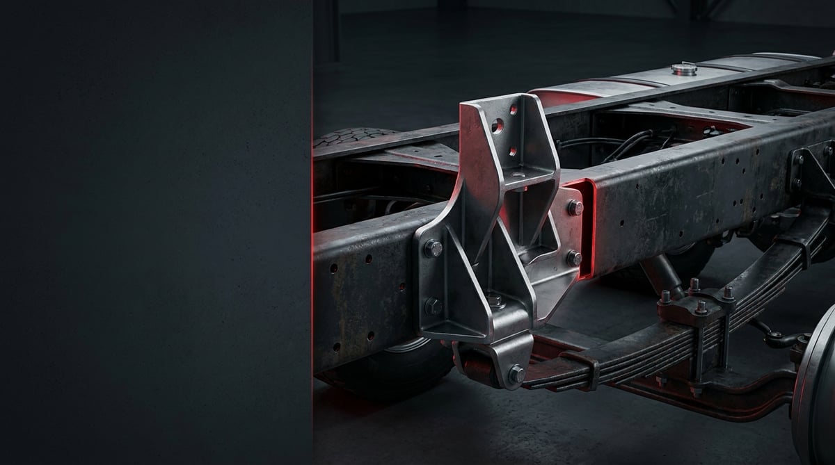
A bracket is the part that works unnoticed but ruins your day the moment it breaks. Most drivers only remember it when they say "there's a rattling noise from underneath"; then the vehicle goes up on the ramp and it turns out the bolt hole in the plate carrying the air tank has torn out, or the dryer bracket has cracked. A chassis mounting bracket is the structural intermediate element that attaches dozens of components to the chassis — from the air brake system to the fuel tank, from the mudguard carrier to the silencer: it carries the load, absorbs vibration and holds the position fixed. This guide covers it in workshop language — what it does, how it fatigues, how to find a crack, how to replace it correctly and how to extend its service life.
E-E-A-T note: This document has been prepared by the VADEN technical team, based on field and product experience with heavy commercial vehicle chassis and air brake system mounting components. The values given here are typical reference ranges; they vary according to chassis section, bracket type, bolt class and year of manufacture. For exact torque, hole spacing and assembly sequence, always refer to the vehicle manufacturer's current service manual. Last updated: July 2026.
For welded repairs on the chassis, welder qualification is certified by examination under ISO 9606.What Is a Chassis Mounting Bracket? Function and Operating Principle
A chassis mounting bracket is a load-bearing mounting element that secures equipment such as air tanks, dryers, valves, fuel tanks, mudguards, silencers and battery boxes to the vehicle's chassis profile (side member or cross member), transferring load and vibration into the chassis.
The operating principle is not as simple as it looks. On a heavy commercial vehicle the chassis constantly twists and flexes while driving; on rough ground and in corners the side members move relative to one another. The bracket's job is to keep the equipment it carries in position throughout this movement while safely distributing the resulting stress. In other words, a bracket does not merely "hold"; it flexes a controlled amount, spreads the load over a wide surface and damps vibration through rubber mounts or clamps. When this balance is disturbed, a fatigue crack begins.
Brackets differ by material and mounting method. Most applications use formed sheet steel (typically 4–10 mm); at high-load points castings or thick plate are used. Attachment to the chassis is made with bolts, with clamps/straps, or by factory welding. In the air brake group, the dryer, four-circuit protection valve and air tank brackets are the most fatigue-prone; they both carry heavy components and absorb vibration coming from the lines.
- Body (carrier sheet or plate): The main element taking the load; its bends and ribs determine rigidity.
- Chassis mounting holes: Must match the side member hole pattern exactly; slotted holes provide assembly tolerance.
- Equipment mounting face: The plane on which the dryer, valve or tank foot seats; flatness is critical.
- Reinforcement rib / gusset: Reduces stress concentration at the bends; cutting it shortens service life.
- Vibration mount / bushing: Rubber or polyurethane; damps micro-movement between bracket and equipment.
- Bolt, nut and washer set: Generally class 8.8 or 10.9, in most applications self-locking or flanged nuts.
- Surface protection: Cataphoretic coating (KTL), powder coating or hot-dip galvanising; the true determinant of corrosion life.
Bolted brackets: the most common and most service-friendly type
These attach to the standard hole row on the side member; the advantage is that in the event of damage they can be replaced without touching the chassis. Their weak point is bolt preload: when torque is lost the joint micro-moves, the hole goes oval and quickly turns into a tear-out. In this type a "loosening bolt" is not a maintenance item — it is an early warning.
Clamp / strap type carriers
Used on cylindrical bodies such as air tanks and fuel tanks. The felt or rubber strip under the clamp prevents both corrosion and fretting wear; when it is crushed or lost, the tank surface rubs directly on metal and weakening from the outside begins.
Welded and cast brackets
At high-load points (stabiliser bar, spring hanger, around the towing gear) factory-welded or cast constructions are found. Intervention here is delicate: unauthorised welding can alter the material structure in the heat-affected zone and create a new crack initiation site. Welding and drilling on the chassis must not be carried out without the manufacturer's bodybuilder guidelines.
| Application area | Typical bracket type | Load character carried | Prominent failure tendency |
|---|---|---|---|
| Air tank carrier (tractor unit / trailer) | Sheet body + clamp/strap | Static weight + vertical vibration | Clamp loosening, loss of felt, fretting corrosion on tank surface |
| Air dryer and valve group (Knorr-Bremse / Wabco type applications) | Formed sheet bracket, bolted | Medium weight + line vibration + thermal cycling | Fatigue crack at bend root, bolt loosening |
| Fuel tank / AdBlue tank console | Heavy sheet console + strap | Variable weight, full-empty cycling | Hole ovalisation, tearing at console corner |
| Silencer / exhaust carrier | Sheet bracket + vibration mount | Thermal expansion + vibration | Mount hardening, paint loss and corrosion from heat |
| Mudguard and spray suppression carrier | Thin sheet arm bracket | Aerodynamic and impact load | Bending, arm fracture, contact with tyre |
| Trailer and semi-trailer equipment consoles (around JOST type couplings) | Heavy sheet / casting | High dynamic load | Weld root cracking, hole tear-out |
Part number verification is essential. With brackets, "looking similar" means nothing. Hole spacing, hole diameter, sheet thickness, bend angle and seating surface vary even within the same model according to year of manufacture, cab type and wheelbase. Before ordering, compare the OE number of the removed part, the vehicle chassis number and the hole dimensions. Forcing a bracket that is a few millimetres out into place concentrates stress at the bolt hole and comes back with a new crack in a short time.
Failure Symptoms and Diagnosis
Bracket failure rarely starts with a sudden break: first comes noise, then a mark appears, then the crack grows. Correct diagnosis means following the path the load travels rather than the area the noise comes from: equipment - bracket - bolt - chassis.
| Symptom | Possible Cause | Check / Verification |
|---|---|---|
| Metallic rattling noise from underneath on rough ground | Micro-movement of the bracket due to a loose bolt or ovalised hole | Raise the vehicle and rock the equipment by hand; if there is movement, check bolt preload and hole roundness |
| Bright ring / fretting mark around the bolt head | Joint has lost torque, surfaces have slipped relative to one another | Check whether the marker line on bolt and nut has shifted; apply check torque with a torque wrench |
| Fine line, paint crack or rust seepage at the bracket bend | Onset of fatigue cracking (stress concentration zone) | Clean the area and inspect with a magnifier; if in doubt, carry out a dye penetrant crack test |
| Visible shift in the position of the air tank or dryer | Clamp loosening or bending of the bracket arm | Check the tension of the equipment on the lines; if there are strain marks on pipes and hoses, the position has shifted |
| Repeated leak at an air line fitting | Bracket movement is continuously straining the line | Verify bracket stability before tightening the fitting; if the leak recurs, the cause is not the joint but the carrier |
| Layered rust and blistering on the bracket-to-chassis contact face | Crevice corrosion caused by moisture and salt | Remove the bolt and open up the surface; if layered rust has caused thickness loss, the bracket must be replaced |
| A second bolt failure in the same area within a short interval | Wrong bolt class, insufficient preload or a fatigued bracket | Check the bolt class (8.8 / 10.9 marking) and washer arrangement; inspect the bracket thoroughly for cracks |
Method for narrowing down the source of the noise
Bracket noises appear at a particular speed or ground type. The most practical method is to grip the equipment with both hands and push and pull it while the vehicle is on the ramp; if the equipment moves a few millimetres on its own, there is play in the joint. The second method is to mark the suspect area with chalk and check the marks after a short road test — friction shows itself immediately.
Where does a crack start, where should you look
A fatigue crack does not start at a random place: it is almost always seen where the geometry changes — at the bend root, at the hole edge, where the weld seam ends and at section reductions. Visual inspection scans these four zones first. Dirt and rust hide cracks; the surface must be opened up with a wire brush before inspection. A fine, straight and directional line on the paint, especially if rust is seeping from its tip, must be taken seriously.
Is the bracket fatigued or has the bolt loosened?
With bolt loosening the surfaces are bright, the hole is still round and torquing solves the problem temporarily. With bracket fatigue, however, the hole has gone oval, the edge has swollen or a line has formed at the bend root; here torquing merely conceals the problem. If the same bolt loosens a second time, it is no longer the bolt but the carrier that should be questioned.
How a crack progresses, how it differs from simple loosening and which findings justify replacement are explained step by step in our chassis bracket crack, loosening and replacement guide.
Further reading
For a plain-language technical overview of this subject, see the reference article on Wikipedia. Always confirm specific figures and procedures against the vehicle manufacturer service data.
Replacement / Installation Steps
Personal protective equipment and safety: The vehicle must be on level, solid ground with the parking brake applied and chocks in place; lifting points must be chosen from the locations indicated by the manufacturer. Never rely on the jack alone — use axle stands. If the bracket of a component connected to the air brake system is to be removed, first exhaust the system pressure — a tank or valve connection under pressure must never be dismantled. Around the exhaust, wait for parts to cool. Safety glasses, gloves and safety footwear are mandatory; there is a risk of parts breaking off when removing rusted bolts. Drilling or welding on the chassis must not be carried out without the manufacturer's bodybuilder guidelines.
- Document the fault: Before dismantling, photograph the bracket's position, the bolt and washer arrangement and the cracked area if present. These records are most useful during reassembly.
- Secure the vehicle: Chocks, axle stands, parking brake and battery isolator; after lifting, visually confirm the vehicle has not settled.
- Depressurise the system: If a bracket belonging to the air brake group is to be removed, drain the tanks and confirm the gauge reads zero. On fuel/AdBlue consoles, lowering the fluid level reduces the weight.
- Support the equipment: Once the bracket is removed, the tank, dryer or box it carries is left free. Support it in advance with a jack, lifting strap or stand; do not strain the connected lines.
- Protect lines and cables: Release the air hoses, fuel lines and wiring harnesses running over the bracket and move them aside; plug open ports.
- Remove the fasteners: Apply penetrating fluid to rusted bolts and wait; choose the patient method rather than forcing. Extract any broken bolt without damaging the chassis hole.
- Inspect the chassis surface and holes: Examine the side member surface for rust, ovalisation, cracks or deformation. If there is damage on the chassis side, replacing the bracket alone is not enough; this must be assessed according to the manufacturer's guidelines.
- Compare the new bracket exactly: Hole spacing, hole diameter, sheet thickness, bend angle and equipment seating face must be identical to the old part. If it does not match, do not fit it; re-verify the reference. Enlarging the hole or "adjusting" the bracket with a hammer creates permanent weakness.
- Complete the surface protection: Clean the rust from the contact faces, cover bare metal with a suitable primer/protective coating; if the manufacturer specifies one, fit the intermediate plate or isolation element.
- Install with new fasteners: Do not reuse locking nuts or deformed bolts. Fit the bolts by hand and position the bracket, then bring them to the torque in the manual in a crosswise, staged sequence. Keep the washer arrangement and bolt length the same as the original.
- Reconnect the equipment and lines: Refit the clamps, mounts and line holders in their original positions; make sure hoses and pipes are not strained and are not rubbing.
- Test and final check: Charge the air system and carry out a leak check, rock the equipment by hand to confirm there is no play. After a short road test, re-check all bolts; carry out one more torque check within the first 500–1,000 km.
Points to Watch (Common Mistakes)
Do not drill holes or weld on the chassis without authorisation. Drilling new holes in the side member or welding on a bracket can alter the stress distribution and lead to permanent damage. Every manufacturer's bodybuilder guidelines define the permitted zones, hole diameters and edge distances. If you cannot access the guidelines, do not carry out the work.
"Repairing" a crack by welding is usually a temporary solution. A fatigue crack is longer than the visible portion, and welding creates a new line of weakness in the heat-affected zone. On brackets with a load-bearing function, the correct approach is to renew the part using the correct reference.
- Enlarging the hole and forcing the part into place: Edge distance is reduced and tear-out becomes almost guaranteed.
- Using the wrong bolt class: Fitting 8.8 instead of 10.9 lowers the preload; in the opposite case there is a risk of over-tightening and brittle failure. Check the class marking on the head.
- Reusing a self-locking nut: The locking feature is largely lost at the first removal.
- Not using a torque wrench: Tightening "as hard as your arm allows" means either a loose or a snapped bolt.
- Omitting the vibration mount: Equipment fitted without a mount transmits vibration directly to the bracket and the chassis; service life is shortened.
- Not fitting the felt under the clamp: Metal-to-metal contact starts wear and corrosion on the air tank surface.
- Forgetting to re-torque after installation: New surfaces bed in and preload drops; if the first check is not carried out, the loosening goes unnoticed.
- Using the bracket as a cable or hose holder: A carrier that has holes drilled in it no longer carries its design load with the same safety margin.
Technical Values and Check Points
The values below are typical / general reference ranges for heavy commercial vehicle chassis mounting components. They vary according to bracket type, sheet thickness, bolt class and manufacturer; for exact values the service manual is definitive.
| Parameter | Typical reference range | Note |
|---|---|---|
| Bracket sheet thickness (general purpose carriers) | approximately 4 – 10 mm | Thicker plate or casting is used on heavy-duty load consoles |
| Bolt class | mostly 8.8 or 10.9 | Verified from the head marking; the class must not be downgraded |
| Hole edge distance (general engineering practice) | typically ≈ 1.5 – 2 times the hole diameter | A smaller distance increases the risk of tear-out |
| Temperature in the exhaust/silencer bracket area | up to approximately 150 – 400 °C | In this area a heat-resistant type is used instead of a rubber mount |
| Air tank operating pressure (equipment carried by the bracket) | approximately 8 – 12.5 bar (≈ 116 – 180 psi) | The system must be fully exhausted before removing the bracket |
| Acceptable free movement of the bracket | in practice close to zero; play felt by hand is not acceptable | Perceptible movement is a sign of preload loss or hole ovalisation |
| First torque check after installation | approximately 500 – 1,000 km | Earlier in heavy site operation |
| Fastener | Typical torque range (class 8.8, dry) | Warning |
|---|---|---|
| M8 bracket bolt | approximately 20 – 28 Nm | Watch for crushing in thin sheet applications |
| M10 bracket bolt | approximately 40 – 55 Nm | Tighten crosswise and in stages |
| M12 bracket bolt | approximately 70 – 95 Nm | The value rises noticeably for class 10.9; consult the manual |
| M16 heavy console bolt | approximately 180 – 240 Nm | On main carrier connections the manufacturer's value must always be used |
| Air tank clamp nut | manufacturer's value | Over-tightening crushes the tank body; the felt must seat properly |
Workshop tip: On every bracket bolt you torque, draw a fine marker line running from the nut across onto the bracket. At the next service, checking whether the line has shifted is far quicker than torque-checking each bolt individually, and it catches loosening before a crack forms.
- At every periodic service, visually scan the air tank, dryer and valve brackets; pay particular attention to the bend root and hole edges.
- Verify that the felt/rubber strip under the clamp is in place and not crushed.
- If there is layered rust blistering on the bracket-to-chassis contact face, remove the bolt and open up the surface.
- Press the vibration mounts by hand and check them for hardening, cracking and oil contact.
- Check whether the hoses and cables running over the bracket show rubbing marks; if there are marks, the bracket position should also be questioned.
- Keep a record of repeated loosening in the same area; a recurring point means it is operating above its design load.
Maintenance and Service Life
Three things determine a bracket's service life: correct installation, corrosion protection and vibration management. When these are in place, a bracket works trouble-free for close to the economic life of the vehicle. When a failure does occur, the cause is generally not a single one; it is accumulated small omissions — salt that was not washed off, a bolt that was not torqued, a mount that was skipped.
- Make visual inspection routine: During work such as an oil change, run a quick scan over the brackets under the chassis; the cost is zero and the return is high.
- Put torque checks on the calendar: After a new installation carry out the first check early, then include it in the service interval.
- Tackle corrosion early: Paint loss and surface rust come before cracking; a small touch-up is cheaper than replacing the bracket.
- Clean off salt and mud build-up: Bracket pockets and the insides of bends hold moisture; an end-of-winter wash extends corrosion life.
- Renew vibration mounts in good time: A hardened mount transmits vibration directly to the bracket and accelerates fatigue.
- Work on a kit basis: When the bracket is renewed, the bolts, nuts, washers, mount and clamp felt should be renewed too; fitting a new bracket with old fasteners is half a job.
- Solve recurring failures at the root cause: If the same bracket cracks a second time, the reason is not the part but excessive load, incorrect installation or lack of damping.
In fleet practice, when the bracket is an item that is "checked to a plan" rather than one that is "replaced when it fails", its cost becomes almost invisible. When it is neglected, however, the moment it breaks it takes the air line, tank or wiring harness next to it with it; the bill goes far beyond that of a single part.
Related categories: Support Bracket · Support Bracket
Application and compatibility: Vehicle compatibility catalogue · Engine compatibility catalogue
Main guide: What Is a Wheel Hub? Wheel Bearing Failure and Symptoms
Tags
Frequently Asked Questions
- Can a chassis mounting bracket be welded if it cracks?
- On brackets with a load-bearing function this is not recommended. A fatigue crack is longer than it appears and the welding heat creates a new weak zone around it. In addition, unauthorised welding on the chassis is contrary to the manufacturer's bodybuilder guidelines. The correct approach is to renew the part using the correct reference.
- The bracket bolts keep loosening, what could be the cause?
- Generally one of three reasons: insufficient preload, a reused locking nut, or a fatigued bracket. If the hole has gone oval, torquing is not the solution. On a second loosening at the same point, check the bracket and the chassis hole as well.
- What happens if the air tank bracket loosens?
- The tank starts to move; the air lines are strained, leaks develop at the fittings and fretting wear begins under the clamp. Movement of a pressurised vessel is also a safety risk; once the symptom is noticed, the vehicle should be taken out of service and the mounting inspected.
- Which bolt class should I use?
- The rule is simple: exactly what was there originally. The 8.8 or 10.9 marking on the head indicates the class. Downgrading the class reduces safety; arbitrarily upgrading it can create a risk of brittle failure. For the exact value and class, the service manual is definitive.
- The bracket hole does not line up with the chassis hole, can I enlarge it?
- No. Enlarging the hole reduces the edge distance and accelerates tear-out; drilling on the chassis, meanwhile, cannot be done outside the zones and dimensions permitted by the manufacturer. If the holes do not line up, the part is most probably the wrong reference; re-verify the correct number.
- How do I tell that a bracket has fatigued?
- Hole ovalisation, a fine directional line at the bend root, rust seeping from the tip of that line, a bright fretting ring around the bolt and repeated loosening are the most reliable signs. In case of doubt, cleaning the surface and carrying out a dye penetrant crack test gives a definitive answer.
- Which other parts should be renewed when replacing a bracket?
- The bolts, self-locking nuts, washer set, vibration mount and clamp felt. A new bracket installed with old fasteners brings the same problem back in a short time. In addition, the corrosion on the contact face must be cleaned off and a protective coating applied.
- How do I select the right bracket?
- Match it using the vehicle chassis number, model year, the equipment to be mounted and the OE number on the removed part. Then physically compare hole spacing, hole diameter, sheet thickness and bend geometry. When these two steps are not carried out together, you run the risk of a part that "looks alike but does not fit".
- How can I confirm on the ramp that the rattle from underneath is coming from a bracket?
- With the vehicle on the ramp, grip the equipment with both hands and push and pull it; if it moves a few millimetres on its own, there is play in the joint. The second method is to chalk-mark the suspect area and check the marks after a short road test, since friction shows itself immediately. Follow the load path rather than the noise: equipment, bracket, bolt, chassis.
- When should I re-torque the bolts after fitting a new bracket?
- Run a short road test straight after installation and re-check every bolt, then torque them once more within the first 500-1,000 km. New surfaces bed in and preload drops, so a skipped first check leaves the loosening unnoticed. After that, include the torque check in the service interval, and take the exact figure from the vehicle manufacturer's current service manual.
Related Articles

Truck Chassis Crack: Causes, Risk Assessment and Weld Repair Limits
What causes a truck chassis crack, how it's inspected and classified, and where stop-drill holes and weld repair reach their limit.
ABS Brake System: How It Works, Warning Light and Faults
Learn how the ABS brake system works on heavy trucks, why the warning light comes on, how to diagnose sensor faults, and the correct replacement steps.
Engine Overheating in Heavy-Duty Trucks: Causes & Fixes
Learn why heavy-duty truck engines overheat, how to read the gauge, step-by-step diagnosis, and how coolant, water pump, thermostat, and fan clutch fail.


