Compressor Cooling Plate & Water Cooling: Faults, Repair & Care
Diagnose, replace and maintain the heavy-truck air compressor cooling plate and water cooling: symptoms, internal-leak testing, torque values and FAQ.
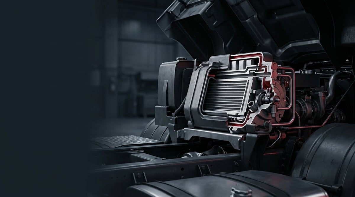
On heavy commercial vehicles, the air compressor runs for hours without interruption under full load, and during this time a significant amount of heat builds up in its body. The key component that carries this heat away is the cooling plate (water-jacketed top cover / cylinder head) that bridges the compressor and the engine cooling circuit, together with its water-cooling passages. In the field, many technicians blame the compressor itself when the real source of the problem is clogging, leakage or gasket failure in this cooling plate. This guide brings together the part's function, typical failure symptoms, correct diagnostic methods, step-by-step replacement and field maintenance, based on heavy commercial vehicle service practice.
This content was prepared by the VADEN technical team. The values below are for general reference; for exact figures such as torque, pressure and temperature, always rely on the OE service manual of the vehicle/compressor. Last updated: September 2026.
Heavy commercial vehicle air brake systems are designed within the framework of ECE R13 (UN/EU braking regulation) and ISO 611.What Is the Compressor Cooling Plate & Water Cooling? Function and Working Principle
The compressor cooling plate is the water-jacketed cast part located on the top cover (cylinder head) of the air compressor, through which the engine coolant flows; it transfers the heat released during compression to the cooling circuit, preventing the compressor and the compressed air from overheating.
On a heavy commercial vehicle, air is compressed in the compressor cylinder from atmospheric pressure to roughly 8–13 bar. By the laws of thermodynamics this compression heats both the air and the metal body; the compressor head can quickly reach the 150–200 °C band. The cooling plate continuously draws this heat with water fed from the engine's main cooling circuit (radiator–thermostat line). This both protects the valve plate and gaskets from thermal damage and lowers the temperature of the compressed air, making it easier for the moisture heading to the air dryer and reservoirs to condense. Insufficient cooling leads to oil coking (carbonization), gasket burn-through and valve plate warping.
- Water-jacketed plate / top cover: Aluminium or cast iron body; inlet–outlet water passages inside.
- Cover gasket (top gasket / plate gasket): A steel-reinforced multi-layer (MLS) or composite gasket separating the water and air passages.
- Water inlet/outlet nipples and hose connections: Fittings connecting to the engine cooling line.
- O-rings and sealing elements: Intermediate elements separating the water–air–oil transitions.
- Valve plate (top group): Directly beneath the plate; directly affected by cooling.
Difference between air-cooled and water-cooled compressors
In light-duty applications and low duty-cycle compressors, the body is cooled by air/fins alone. However, on high duty-cycle heavy commercial vehicles (tractor units, buses, construction machinery) the water-cooled plate is standard, because air cooling alone cannot handle the sustained recharge air and continuous filling load. Water-cooled designs are usually pressure-lubricated with engine oil as well.
Cooling circuit integration
The plate is connected to the engine coolant circuit in series or in parallel. The water is usually taken from the engine block, passes through the compressor plate, and is fed into the thermostat/radiator return line. For this reason, an air pocket, low level or a blocked hose in the engine cooling system also directly disrupts compressor cooling.
OE context and aftermarket structure
Heavy commercial compressors are predominantly Knorr-Bremse, Wabco (ZF), Bendix and Bosch type designs, and their cooling plate / top group geometries vary by engine family (e.g. Mercedes OM4xx/OM5xx, MAN D20/D26, DAF PACCAR MX, Volvo/Renault D-series). VADEN ORIGINAL cooling plate, water pipe and water connector groups are produced as equivalents of these OE types, with the mounting hole pattern, water passage cross-section and gasket surface compatible with the original.
| Compressor type (equivalent) | Typical engine / vehicle family | Cooling | Note |
|---|---|---|---|
| Knorr-Bremse type single cylinder | Mercedes OM457, MAN D20/D26 | Water + oil | Water-jacketed top plate common |
| Wabco / ZF type twin cylinder | DAF MX-13, Volvo D13 | Water + oil | High flow-rate charging |
| Bendix type (BX/Tu-Flo type) | North American heavy tractor units | Water | Separate water inlet/outlet |
| Bosch type | Various buses / trucks | Water + oil | Aluminium plate variant |
Part number verification is essential. Even within the same engine family, the plate/gasket geometry can change depending on the production year and compressor revision. Before ordering, always compare the OE number of the old part, the direction of the water passage and the hole spacing; do not select a part relying on the engine type alone.
Failure Symptoms and Diagnosis
Problems in the cooling plate and water cooling group mostly reveal themselves in three ways: coolant loss, excessive water/oil in the air system, and overheating of the compressor. The table below is the starting point for field diagnosis.
| Symptom | Possible Cause | Check / Verification |
|---|---|---|
| Continuous drop in antifreeze/water level, no external leak | Plate gasket punctured between the water–air passage; internal leak | Pressurized cooling test; check for water/foam when draining the air reservoir |
| Excessive water/emulsion coming from the air reservoir and dryer | Water is crossing to the air side (gasket or cracked plate) | Drain the reservoirs; milky fluid indicates an internal leak |
| Compressor body excessively hot, oil darkened | Water passage blocked; insufficient cooling | Measure inlet/outlet hose temperature difference; check passage flow |
| External water/oil leak from the plate–block joint | Gasket fatigue, bolt loosening, surface warping | Clean, run dry, visually track the leak point |
| Oil film in the coolant / foam in the expansion tank | Oil is leaking into the water jacket (gasket/O-ring) | Observe the expansion tank; analyze the oil–water mixture |
| Pressure build-up time increased, compressor charging continuously | Valve plate leak caused by overheating | Fill-time test; valve plate and plate temperature |
| Leak after freezing/cracking in the cooling hose in winter | Freeze damage in the water passage | Measure antifreeze concentration; look for a crack in the plate body |
Internal leak or external leak?
This is the first distinction. In an external leak you see a trace on the ground/body. In an internal leak the antifreeze decreases without any external trace and water comes from the air reservoir; this is the most typical sign of a crack in the gasket or plate that separates the water and air passages. When an internal leak is suspected, the vehicle must be stopped, because water entering the air system impairs brake performance and the dryer.
Pressurized cooling test
With the engine cold, the cooling system is pressurized with a pump up to the manufacturer's test pressure limit (typically the 1–1.5 bar band, exact value in the vehicle manual). If the pressure drops and there is no external trace, the compressor plate is strongly suspected. The air side of the compressor is removed and the water side is pressurized to confirm bubbles passing from the passage to the air side.
Thermal and flow check
With the engine hot, the water inlet and outlet nipples are measured with a non-contact thermometer. A healthy plate should show a measurable temperature difference between inlet and outlet and free flow. If there is no difference, or if the outlet is excessively hot, passage blockage (scale/corrosion/deposits) should be considered.
Standards and further reading
This subject is governed by the equipment rules for air-braked commercial vehicles. In the United States the federal air brake standard, FMVSS 121 (49 CFR 571.121) defines the reservoirs, protection and timing a compliant system must provide, and Europe applies the equivalent limits of UNECE Regulation No. 13. For further detail, see the illustrated reference guide at airbrakecompressor.com. Always confirm specific figures against the current regulation and the vehicle manufacturer service data.
Readers outside the United States should work from their own national framework: in the United Kingdom the braking system must be maintained under regulation 18 of the Road Vehicles (Construction and Use) Regulations 1986, and in India the governing rules are published by the Ministry of Road Transport and Highways.
Replacement / Installation Steps
PPE and safety: Before the procedure, fully drain the air reservoirs (0 bar in the system), let the engine cool (hot antifreeze scalds), disconnect the negative terminal of the battery. Use protective goggles and gloves. Antifreeze is toxic and cannot be disposed of into the environment; collect it in a suitable container.
- Secure the system: Release the air pressure, drain the coolant to an appropriate level, disconnect the battery and immobilize the vehicle.
- Label the connections: Mark and disconnect the water inlet/outlet hoses, the air line and, if present, the oil feed/return pipes. Photograph the directions.
- Remove the plate: Loosen the top cover/plate bolts in a crossing sequence and in stages. Do not warp the surface by forcing from one side.
- Clean the old gasket and surface: Clean the old gasket residue on the plate and block surface with a soft scraper; do not let debris fall into the water and air passages.
- Check surface flatness: Measure the flatness of the mating surface with a straightedge and feeler gauge; a warped plate causes leaks to recur, renew the part if necessary.
- Check the passages: Verify that the water passages of the new/cleaned plate are open, burr-free and clean.
- Fit the new gasket and O-rings: Paying attention to their direction, fit them dry or with the thin sealant recommended by the manufacturer; do not slide the gasket.
- Seat the plate: Lower the part straight, start the bolts by hand, hold all of them without forcing any bolt.
- Tighten to torque: Apply the manufacturer's specified torque in a crossing (star) sequence and in 2–3 stages. Do not apply full torque in one pass.
- Reconnect the connections: Connect the water, air and oil lines according to the labels; check the clamps.
- Fill and test: Fill the cooling system with the correct antifreeze mixture, bleed it; start the engine and build up pressure, check for leaks and internal leaks (reservoir draining).
Points to Watch (Common Mistakes)
Most common mistake: Tightening the bolts in one direction and at full torque instead of crosswise and in stages. This warps the plate surface and the gasket leaks again shortly.
Second common mistake: Replacing only the gasket and ignoring the water passage blockage. A blocked passage does not solve the cooling; the new gasket burns as well due to excessive heat.
- Letting old gasket residue fall into the water/air passage — the debris goes to the valve plate.
- Using the wrong gasket direction or a double gasket — it disrupts the transition separating water and air.
- Applying too much sealant paste — excess paste enters the passage and narrows the flow.
- Using only water instead of antifreeze — it causes corrosion and freeze damage in winter.
- Running without bleeding — an air pocket creates a hot spot and a false leak impression.
- Reusing a warped/worn plate — a surface out of flatness leaks again.
- Connecting the oil feed/return line reversed — it disrupts the lubrication and cooling balance.
Technical Values and Check Points
The values below are typical/general references for heavy commercial compressor applications. The exact value is always the one stated in the service manual of the vehicle and the compressor.
| Parameter | Typical / general reference range | Note |
|---|---|---|
| System working pressure (cut-out) | ~8–13 bar (≈116–189 psi) | Depends on pressure regulator/valve setting |
| Compressor head working temperature | ~150–200 °C band | Carbonization risk in excessive heat |
| Compressed air outlet temperature (target) | Generally ≤ ~200 °C | If higher, cooling is insufficient |
| Coolant temperature (engine normal) | ~80–95 °C | According to the thermostat range |
| Cooling system test pressure | ~1–1.5 bar | Pressurized leak test |
| Antifreeze concentration | ~40–50% | Freeze/corrosion protection |
| Connection | Typical torque band (general reference) | Application |
|---|---|---|
| Plate / top cover bolts (M8) | ~20–30 Nm | Crosswise, 2–3 stages |
| Plate / top cover bolts (M10) | ~40–55 Nm | Crosswise, 2–3 stages |
| Water nipple / fitting | ~25–40 Nm | Over-tightening cracks it |
Tip: The torque value varies according to the compressor manufacturer and the bolt class. If the value is unknown, rely on the table in the service manual instead of tightening arbitrarily; be especially careful not to strip the threads on an aluminium plate.
- Presence of a water inlet–outlet temperature difference (flow confirmation).
- Whether there is an oil film/foam in the expansion tank.
- Amount of water/emulsion when draining the air reservoir.
- Flatness of the plate mating surface (feeler gauge check).
- Antifreeze level and concentration remaining stable.
- Re-checking the bolt torques after the first 500–1,000 km.
Maintenance and Service Life
The service life of the cooling plate and water cooling group depends largely on the maintenance of the engine cooling system. Clean antifreeze at the correct concentration with corrosion inhibitors prevents deposits and scaling inside the passages, ensuring the plate works trouble-free for years. In dirty systems or those fed with water only, the passages clog, cooling collapses and the gasket burns prematurely.
- Change the antifreeze at the interval recommended by the manufacturer; measure the concentration regularly.
- Periodically check the expansion tank for signs of oil/foam.
- Regularly drain the air dryer and reservoirs to catch an internal leak early.
- Visually inspect the cooling hose, clamps and nipples for cracks/leaks.
- As a rule, renew the gasket and O-rings during a major compressor overhaul.
- Verify the antifreeze freeze-protection level when heading into winter.
When the symptoms are caught early, in most cases changing only the gasket and O-ring set is sufficient; a neglected internal leak, on the other hand, turns into damage to the valve plate, bearing and even the entire compressor, multiplying the cost. That is why "a little antifreeze loss" should not be taken lightly.
With correct diagnosis, correct gasket selection and proper torque, compressor cooling plate problems are solved with confidence. The VADEN ORIGINAL Compressor Cooling Plate and Water Pipe groups are offered in our catalogue in stock, with cooling plate, gasket kit and water pipe solutions compatible with the OE types of heavy commercial vehicle compressors, to keep cooling performance at its original level.
Related categories: Cooling Plate · Water Pipe · Water Connector · Air Suction Pipe · Air Pressure Pipe
Related technical guides: Compressor Piston-Ring & Connecting Rod: Repair Guide · Truck Air Compressor Overhaul Kit: Head, Valve Plate, Gasket · Compressor Crankshaft & Drive Assembly: Failure & Replacement Guide · Compressor Valve & Unloader: Fault, Replacement & Care Guide
Application and compatibility: Vehicle compatibility catalogue · Engine compatibility catalogue
Vehicles and engines mentioned in this guide: MAN D2676 · MAN D2066 · Volvo D13 · DAF MX-13 · Mercedes-Benz OM457
Main guide: Water Pump: Faults, Replacement & Maintenance Guide
Tags
Frequently Asked Questions
- The compressor is losing antifreeze but there is no external leak, why?
- The most likely cause is that the plate gasket separating the water and air passages is leaking internally, or that the plate body is cracked. Since the antifreeze crosses to the air side, you see no external trace; when you drain the air reservoir, water/emulsion comes out. The vehicle should be stopped and diagnosed.
- Why is water and milk-like fluid coming from the air reservoir?
- Normal condensation water is clear; a milky consistency (emulsion) indicates that antifreeze or oil has mixed into the air system. A cooling plate internal leak and an air dryer fault should be evaluated together.
- Is it enough to change only the gasket, or should I replace the whole plate?
- If the plate surface is flat, the passages are open and the body is crack-free, in most cases the gasket and O-ring set is sufficient. If the surface is warped, the passage is blocked or the body is cracked, a complete replacement of the plate is required.
- Is compressor overheating related to the cooling plate?
- Yes. A blocked water passage or weak water flow cannot carry the heat away; the compressor head overheats, the oil carbonizes and the valve plate starts to leak. In case of overheating, the cooling flow should be checked first.
- Can I use only pure water instead of coolant?
- No. Pure water contains no corrosion inhibitor, causes scale and rust in the passages, and cracks the plate by freezing in winter. Antifreeze of the type and concentration specified by the manufacturer must always be used.
- How do I determine the correct bolt torque?
- The exact value is in the compressor/vehicle service manual. As a general reference, a band of ~20–30 Nm can be given for M8 and ~40–55 Nm for M10; however, the crossing sequence and staged tightening are as important as the value itself. Be careful not to strip the threads on an aluminium plate.
- Will the VADEN cooling plate fit my original compressor?
- VADEN ORIGINAL cooling plate and water cooling groups are produced as equivalents of the relevant OE types, with connection and passage geometry compatible with the original. Even so, we recommend verifying before ordering by comparing the OE number of the old part and the direction of the water passage.
- How do I clean the water in the air system after replacement?
- Once the leak is fixed, drain the air reservoirs and the dryer, renew the dryer cartridge if necessary, and observe the system over several fill-drain cycles. When heated water remains in the air system, the risk of corrosion and valve freezing persists.
- Why is a water-cooled plate used on trucks instead of air cooling?
- In light-duty applications and low duty-cycle compressors the body can be cooled by air and fins alone. On a heavy commercial vehicle the compressor runs for hours at full load and the head can reach the 150–200 °C band; air cooling alone cannot handle the sustained recharge air and the continuous filling load. That is why the water-jacketed plate is standard on tractor units, buses and construction machinery, usually together with pressure lubrication from engine oil.
- Should I apply sealant paste when fitting the new plate gasket?
- As a rule the gasket is fitted dry; only the thin sealant recommended by the manufacturer is acceptable. Excess paste enters the passage, narrows the flow and weakens cooling. A double gasket, or a gasket fitted the wrong way round, disrupts the transition that separates water from air. Once seated, do not slide the gasket and do not let old gasket residue fall into the water or air passage, because the debris travels to the valve plate.
Related Articles
Compressor Connection Hardware: Faults, Replacement, Care
How truck air compressor adapters, bolts, plugs and hoses fail, how to diagnose leaks and blockages, replace them correctly and extend service life.
Compressor Repair and Gasket Kit: Faults, Replacement, Care
Diagnosing air compressor gasket failure on trucks: choosing the right repair kit scope, preparing surfaces, torquing correctly and extending seal life.
Compressor Valve & Unloader: Fault, Replacement & Care Guide
Low air pressure on a truck, or a compressor that never cuts out, usually means worn intake and discharge reed valves or a stuck unloader: how to fix it.


