Brake Chamber, Diaphragm & Hose: Faults, Replacement, Care
Learn how to spot a leaking brake chamber, measure push rod stroke, cage the power spring safely and replace the unit and hose without risk on heavy trucks.
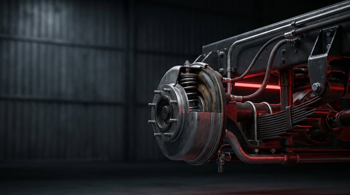
What starts braking on a heavy commercial vehicle is air: pressure reaches the chamber, the diaphragm swells, and the push rod carries the force to the slack adjuster. The least visible yet hardest-working link in this chain is the brake chamber and the flexible hose feeding it. When a vehicle comes in with "the brakes don't hold", "the parking brake won't release" or "it's leaking air", the cause found under the chassis is usually not a valve but a torn diaphragm inside a mud-packed chamber or a hose worn thin by chafing. This guide explains how a brake technician reads the fault, the safe replacement sequence and the maintenance discipline that extends service life.
What Is a Brake Chamber / Diaphragm & Hose? Function and Operating Principle
Brake Chamber / Diaphragm & Hose is the brake actuation group made up of the pneumatic actuator that converts pressure into mechanical thrust and the flexible line that carries this pressure to the chamber. On heavy commercial vehicles, at a typical working pressure of 6–8.5 bar, a Type 20–24 diaphragm chamber produces roughly 8–11 kN of thrust; usable stroke is generally in the 55–75 mm range depending on chamber type.
The same part is known by several names in the field and in catalogues: brake pot, brake actuator, diaphragm chamber, membrane chamber (Membranzylinder in German sources), spring brake chamber, combined chamber, and, for the flexible line running to the wheel, brake hose or air hose. All belong to the same actuation family; whichever name is used to search for it, the selection criteria are identical: axle type, chamber type number, mounting flange and OE reference number.
The operating principle is a direct force conversion. When the brake pedal is applied, the foot valve sends compressed air into the hoses of the relevant circuit. Air fills the pressure chamber and pushes the fabric-reinforced rubber diaphragm; the pressure plate drives the push rod outward, the rod rotates the slack adjuster, and the S-cam or disc brake mechanism presses the lining against the drum or the disc. When the pedal is released, pressure is exhausted and the return spring pulls the diaphragm back to its initial position. The force produced is a simple product: the effective area of the diaphragm times system pressure. That is why, at the same pressure, a Type 24 chamber produces markedly more force than a Type 16, and why the type number is never substituted with "whatever is close".
A spring brake chamber (combined chamber) has a second housing and the logic is reversed. The powerful force spring inside it provides the parking and emergency brake. While there is pressure in the system, air compresses the spring and the brake stays released; when pressure drops or the parking brake is applied, the spring extends and mechanically brakes the vehicle. In other words, the parking brake does not hold with air, it holds in the absence of air. This safety logic is the hardware equivalent of the emergency brake requirement under ECE R13, and it also explains why this part must never be dismantled casually: an uncaged force spring carries lethal energy the moment the housing is opened.
In which OE systems and vehicles is it found?
The type and mounting geometry of the brake chamber / diaphragm & hose group depend far less on the vehicle make than on the brake system family and the axle type built around it. The OE system families most often encountered in the field originate from Knorr-Bremse and Wabco; flange hole pattern, stud length and push rod form differ between drum-braked and disc-braked axles. At vehicle level, Mercedes-Benz Actros and Axor, MAN TGS and TGX, DAF XF and CF, Volvo FH and FM, Scania R and G, Iveco Stralis series along with trailer axles equipped by SAF, BPW and JOST are the applications where chamber replacement is seen most often in the workshop. These names are given only as application examples; even on the same tractor unit, the front axle, rear axle and trailer use different chamber types. The correct part is determined not by a brand name but by axle/chassis code, chamber type number and OE number.
Difference between a single-acting diaphragm chamber and a spring (combined) chamber
A single-acting diaphragm chamber contains only one pressure housing and one diaphragm; it is generally used on front axles, brakes when pressure arrives and releases via the return spring when pressure is cut. Because no mechanical energy is stored inside, removal is safer. A spring (combined) chamber, on the other hand, combines the service housing and the force spring housing in a single body and is standard on drive rear axles and trailers. The mechanical release bolt at the rear of the spring housing allows the brake to be released by hand when there is no air. On most modern products this body is permanently sealed: the spring housing is not serviced, it is replaced complete.
Brake hose, standards and components
The flexible line running to the chamber has to absorb suspension movement between axle and chassis; on heavy commercial vehicles it is produced from reinforced rubber hose or thermoplastic tubing. The relevant standard family includes ISO 7628 (thermoplastic air brake tubing), DIN 74310 (air brake hose and fitting connections) and SAE J1402 (air brake hose) references; the vehicle's entire brake equipment is additionally assessed under ECE R13. Since the applicable standard and dimension class can vary by application, exact data must be verified from the relevant OE catalogue. The main components of the group are as follows:
- Chamber body and cover: the metal housing forming the pressure chamber, joined by a clamp band or by crimping.
- Diaphragm (membrane): fabric-reinforced rubber element; the actual part that converts pressure into force.
- Pressure plate and push rod: the mechanical path transferring force to the slack adjuster.
- Return spring and force spring: the first pulls the diaphragm back to its initial position, the second provides the parking and emergency brake on spring types.
- Mechanical release bolt: the safety element that cages the force spring and releases the brake by hand.
- Clevis, pin and lock nut: the adjustable end connecting the push rod to the slack adjuster.
- Drain holes: the openings that expel moisture entering the housing and must never be blocked.
- Brake hose, fitting and mounting studs: the flexible line carrying the pressure and the elements securing the chamber to the bracket.
| Type (Membranzylinder Typ) | Approx. effective area (cm²) | Typical thrust at 6.5 bar (kN) | Typical total stroke (mm) | Common application |
|---|---|---|---|---|
| Type 12 | approx. 77 | 4.5–5.5 | 50–57 | Light/medium front axle, some trailer applications |
| Type 16 | approx. 103 | 6.0–7.0 | 57–64 | Tractor unit and truck front axle |
| Type 20 | approx. 129 | 7.5–8.8 | 57–64 | Front axle and medium-duty rear axle |
| Type 24 | approx. 155 | 9.0–10.5 | 64–75 | Drive rear axle, trailer axle |
| Type 30 | approx. 194 | 11.5–13.0 | 64–75 | Heavy trailer and special applications |
| Combined (e.g. 20/24, 24/24, 24/30) | Service housing according to type | Service force and spring force are assessed separately | Service stroke according to type | All axles requiring a parking/emergency brake |
How do you recognise a Brake Chamber / Diaphragm & Hose failure?
Brake chamber / diaphragm & hose failures fall into two headings in workshop language: leaking air and failing to produce force. The first is read by ear, the second by the behaviour of the vehicle. The most frequent situation in the field is not a diaphragm bursting all at once, but the drain hole clogging with mud so that moisture trapped inside the housing wears the diaphragm and the spring from within over the years. The table below matches symptoms with likely causes and the method of verification.
| Symptom | Possible cause | Check / verification |
|---|---|---|
| Continuous hissing from the chamber when the brake is pressurised | Torn diaphragm or loss of sealing at the body-to-cover joint | Soapy water bubble test with the system charged and the pedal held down |
| Reservoir pressure slowly falls while the vehicle is parked | Leak at the spring housing or hose connection, fatigued fitting seal | Measuring the pressure drop rate with the engine stopped; isolating circuits to locate the leak |
| Parking brake will not release, the vehicle does not move | Pressure is not reaching the force spring housing: crushed/blocked hose, faulty valve or chamber | Pressure measurement at the spring housing inlet; checking the hose for crushing along its route |
| One wheel bites later than the others, the vehicle pulls to one side under braking | Stroke loss at one chamber, partial diaphragm leak or restriction in the hose | Stroke measurement and comparison per axle; swap-testing the hoses for internal restriction |
| Push rod stroke longer than normal, slack adjuster rotates too far | Lining wear, slack adjuster not working or clevis adjustment lost | Stroke measurement on the rod in pressurised and unpressurised positions; observing adjuster movement |
| Rust, swelling, mud build-up or a broken plug on the chamber body | Blocked drain holes, moisture inside the housing, stone impact damage | Visual inspection; checking that drain holes are clear and that the body is not deformed |
| Cracks, chafe marks or swelling on the hose, or damp dust at the fitting base | Aged rubber, incorrect routing, missing clip, loose fitting | Checking for surface cracks by flexing the hose by hand; tracing the route through full suspension travel |
| The wheel releases slowly after the brake is released, the hub runs hot | Weakened return spring, internal corrosion in the chamber, one-way restriction in the hose | Measuring the release time; comparing wheel temperatures |
Leak testing with soapy water
The fastest and cheapest way of hunting an air leak is still a soapy water solution. The system is brought up to working pressure; the body-to-cover joint, drain holes, fittings and hose ends are wetted, and bubbles show where the leak is. The critical distinction is this: a leak with the pedal released points to the spring housing or the parking line, while a leak with the pedal applied points to the service housing and the diaphragm. Continuous air from the drain hole is the classic sign of an internal diaphragm leak.
Assessing condition by stroke measurement
The most objective indicator of a brake chamber's health is push rod stroke. The measurement is made by marking the rod in the unpressurised position and reading the amount of movement during full braking. Usable stroke is expected to leave a clear margin against total stroke; a stroke approaching the limit points to lining wear or a slack adjuster that is not working. The stroke of the two wheels on an axle should be close to each other. The acceptance limit is specific to the chamber type and the vehicle and is taken from the service manual.
Circuit isolation and hose testing
If there is a pressure drop but the leak cannot be located, the circuits are isolated one by one to narrow the search area. Where a hose is suspected, two checks are made: external inspection for cracks and chafe marks, and internal inspection for restriction. A hose narrowed on the inside looks sound from the outside but lengthens the fill and exhaust time of the chamber; this shows up as one wheel biting or releasing late.
To see the whole circuit that feeds this flexible line, in order from compressor to wheel, our guide how the air brake system works on heavy commercial vehicles follows the chain end to end.
Standards and further reading
This subject is governed by the equipment rules for air-braked commercial vehicles. In the United States the federal air brake standard, FMVSS 121 (49 CFR 571.121) defines the reservoirs, protection and timing a compliant system must provide, and Europe applies the equivalent limits of UNECE Regulation No. 13. For further detail, see the illustrated reference guide at airbrakecompressor.com. Always confirm specific figures against the current regulation and the vehicle manufacturer service data.
Outside the United States the equivalent duties sit in national law. In the United Kingdom, regulation 18 of the Road Vehicles (Construction and Use) Regulations 1986 requires every part of the braking system to be maintained in good working order. In Canada, air brake systems fall under the Motor Vehicle Safety Regulations, which contain CMVSS 121.
How is a Brake Chamber / Diaphragm & Hose replaced? Step by step
- Secure the vehicle: Park on level, solid ground, switch off the ignition, chock the wheels and disconnect the battery isolator. Do not rely on the parking brake — the part you are about to remove is the parking brake itself.
- Exhaust system pressure: Drain the reservoirs and confirm on the gauge that pressure has reached zero. On a spring chamber this step will apply the brake; that is why the next step is mandatory.
- Cage the force spring mechanically: Turn the release bolt at the rear of the spring housing in the direction and to the full extent specified by the manufacturer to cage the spring, and confirm by hand that the brake has released. If the bolt binds, the part is damaged; do not continue by applying force.
- Clean the area: Free the surroundings of the chamber, the flange studs and the fittings from mud, salt and rust using compressed air and a wire brush. Dirty removal both damages the threads and carries particles into the line.
- Mark and disconnect the air lines: Label the lines so the service and parking inlets are not confused, open the fittings while counter-holding the body, and immediately plug the open ports with clean caps.
- Release the push rod connection: Remove the retaining element of the clevis pin, take out the pin and note the adjustment length on the rod. This dimension is the reference for fitting the new part with the correct stroke.
- Remove the chamber and inspect the bracket: Loosen the flange nuts progressively and take out the chamber; combined chambers are heavier than expected, so take the weight in your hand. Check the bracket for cracks, the studs for thread damage, the slack adjuster for play and stiffness — fitting a new chamber to a damaged bracket brings the fault back in short order.
- Verify the new part: Place the new chamber alongside the old one and compare type number, flange stud spacing, push rod length and inlet port position. Make sure the drain holes will face downwards after installation.
- Install and torque: Seat the chamber on the bracket and tighten the flange nuts in a crosswise sequence to the torque specified by the manufacturer. Set up the push rod connection to the dimension you noted, tighten the lock nut and renew the retaining element of the pin. Connect the air lines to the correct inlets.
- Release the spring and set the adjustment: Return the release bolt to the operating position as defined by the manufacturer. Charge the system, check the slack adjuster setting according to the procedure, and measure the stroke to compare it with the other wheel on the axle.
- Test and carry out the final check: Scan all connections with soapy water at full pressure and verify the parking brake by applying and releasing it several times. Carry out a low-speed brake test; after the drive, review the fittings and the stroke value once more.
What are the common mistakes when replacing a Brake Chamber / Diaphragm & Hose?
- Changing the type number: Fitting a different type because "this was on the shelf" upsets axle force distribution and type approval.
- Fitting without measuring push rod length: Incorrect adjustment means either a constantly dragging brake or a wheel that bites late.
- Installing with the drain holes facing upwards: Water entering the housing cannot escape, and the diaphragm and spring corrode from the inside.
- Using the old hose with a new chamber: Fatigued rubber repeats the same failure in short order; hose and chamber must be assessed together.
- Routing the hose taut or where it will chafe: A line that goes tight through full suspension travel cracks at the fitting base within a few thousand kilometres.
- Confusing the service and parking inlets: The brake works in reverse; the parking brake either fails to hold or fails to release.
- Tightening the flange nuts by feel: Insufficient torque leads to loosening, excessive torque to stud and flange deformation.
- Forgetting to return the release bolt to the operating position: The parking brake is left out of action and the vehicle will not hold on a gradient.
- Reusing the safety pin and clip: A fatigued retaining element drops out with vibration and the clevis connection separates.
- Skipping the leak and stroke test after replacement: A small fitting leak comes back as a pressure drop on a long haul.
Brake Chamber / Diaphragm & Hose technical values and inspection points
Brake chamber / diaphragm & hose values listed below are the general reference ranges commonly encountered in heavy commercial vehicle air brake systems. Axle type, chamber type and equipment generation change these ranges; for exact data, refer to the vehicle manufacturer's current service manual.
| Parameter | Typical range (general reference) | Note |
|---|---|---|
| System working pressure | 6.0–8.5 bar (87–123 psi) | The governor cut-out value is vehicle specific |
| Full application pressure of the service brake | Approximately 6.0–8.0 bar | Force increases in direct proportion to pressure |
| Pressure at which the spring brake is fully released | Approximately 5.5–6.5 bar | Below this the brake engages progressively |
| Pressure at which the spring brake starts to engage | Approximately 3.5–4.5 bar | Emergency brake logic; assessed under ECE R13 |
| Force spring parking brake force (Type 24 order of magnitude) | Approximately 9–13 kN | Varies with type and manufacturer |
| Total push rod stroke | 50–75 mm (depending on type) | Type 12–16 in the lower band, Type 24–30 in the upper band |
| Usable stroke margin | A clear portion of total stroke is kept in reserve | The acceptance limit is vehicle specific; taken from the manual |
| Left-right stroke difference on an axle | Kept as small as possible | The greater the difference, the more the vehicle pulls under braking |
| Operating temperature range | Approximately -40 °C to +80 °C | Local temperature near the drum is higher |
| Hose burst safety margin | A safety factor well above working pressure | The standard equivalent is verified from the ISO 7628 / SAE J1402 family |
| Connection point | Typical torque band (general reference) | Application note |
|---|---|---|
| Chamber flange nuts (axle bracket) | 150–210 Nm | Tightened progressively in a crosswise sequence; stud threads must be clean |
| Air line fitting (chamber inlet) | 20–40 Nm | Overtightening damages the fitting body and the sealing face |
| Push rod clevis lock nut | 30–60 Nm | Tightened after the adjustment length has been verified |
| Hose retaining clip bolt | 8–15 Nm | Secures the hose without crushing it; tightened last |
| Mechanical release bolt | Value defined by the manufacturer | Never forced tight; if damaged, the chamber is replaced |
- Is there rust, swelling, denting or impact damage on the chamber body?
- Are the drain holes clear, facing downwards, and are their plugs in place?
- Is a leak audible with the pedal applied and with it released?
- Is push rod stroke within the limit, and is the left-right difference acceptable?
- Are the clevis pin, clip and lock nut sound and secured?
- Are there cracks, swelling or chafe marks on the hose, or damp dust at the fitting base; does the line go tight or chafe through full suspension travel?
- Does the slack adjuster move freely, and is slack adjuster play normal?
- Does the parking brake work without delay in the apply-release test?
How is a Brake Chamber / Diaphragm & Hose maintained and its service life extended?
Brake chamber / diaphragm & hose assemblies have no fixed "replacement interval"; three things determine service life: the dryness of the air, drainage of the housing and installation discipline. A chamber fed with dry air, with clear drain holes and installed to the correct torque, is one of the longest-lived parts on the vehicle. A chamber working in a system that pushes moist air, or buried in mud, comes back to the workshop with a diaphragm leak before the year is out. On routes where road salt is used in winter, corrosion is the single most decisive life-shortening factor observed in the field.
- Air dryer discipline: Replace the dryer cartridge at the manufacturer's interval. Moisture entering the system means corrosion inside the chamber and freezing in winter.
- Reservoir draining: Drain water from the reservoirs regularly; accumulated water is carried along the lines as far as the chamber.
- Keeping the drain holes clear: Check the drain holes in the body at every service and clear mud and ice plugs.
- Periodic leak scanning: Scan all chambers and fittings with soapy water at each service; a small leak caught early does not turn into a roadside breakdown. When washing, do not aim pressurised water directly at the chamber.
- Stroke monitoring: Make stroke measurement a routine. Increasing stroke gives early warning about the lining, the slack adjuster and the chamber.
- Hose routing check: Keep the clips complete and the hose free and clear of chafing; renew a hardened hose before it fails.
- Axle-based approach: Plan chamber replacement as an axle pair rather than a single wheel; this is how brake balance is preserved.
- Monitoring after intervention: After any job involving the brake system, repeat the leak and stroke check over the first few hundred kilometres.
For fleet operators the most efficient approach is to plan the brake chamber not as a single part but as a set together with the hose, the clevis and the mounting elements. On an axle already stripped for a lining or drum job, renewing a fatigued chamber and hose during the same service is far more economical than bringing the vehicle back into the workshop a second time a few months later.
Related categories: Brake Cylinder · Hose
Main guide: Brake Chamber: Fault Diagnosis, Replacement and Maintenance Guide
Tags
Frequently Asked Questions
- Can the vehicle be driven if the brake chamber diaphragm bursts?
- It should not be. A torn diaphragm largely disables the service brake on that wheel and drops system pressure through a continuous air leak; as pressure falls, the spring brakes may engage at an unexpected moment. The vehicle should be brought to a safe stop and taken into service.
- What is the difference between a brake pot and a spring brake chamber?
- The difference is whether or not mechanical energy is stored inside. A single-acting diaphragm chamber (brake pot) operates only the service brake: it brakes when pressure arrives and releases via the return spring when pressure is cut. In a spring (combined) chamber, a powerful force spring in a second housing provides the parking and emergency brake; the brake stays released as long as air pressure compresses the spring. The practical consequence is this: on a single-acting chamber it is enough to exhaust system pressure, whereas on a spring chamber the spring must additionally be caged with the mechanical release bolt. The two cannot be fitted in place of each other.
- How is the brake chamber type determined, and can a Type 24 be fitted instead of a Type 20?
- The type number expresses the effective area of the diaphragm and is part of the vehicle's brake force distribution calculation. Fitting a Type 24 instead of a Type 20 increases force at that wheel, upsets axle balance and electronic brake regulation, and takes the vehicle outside its type approval. The correct type is determined by axle type, the type information on the original chamber and the OE reference number.
- When should the brake chamber hose be replaced?
- The hose is replaced according to its condition rather than its calendar age. If a network of cracks, hardening, swelling, chafe wear or damp dust at the fitting base is visible on the surface, it must be renewed. Keeping the old hose at a point where the chamber is being replaced is usually a false economy; the two should be assessed together.
- If the parking brake will not release, is the chamber at fault?
- Not always. Failure of the parking brake to release can also stem from insufficient pressure reaching the spring housing: a crushed or blocked hose, a faulty park valve or low system pressure produce the same symptom. The correct sequence is to measure pressure at the spring housing inlet first, then eliminate the hose and the valve. If pressure is adequate and the brake still does not release, the chamber is suspect.
- How many kilometres does a brake chamber last before replacement?
- There is no fixed mileage figure. Service life is determined by the dryness of the air, exposure to road salt and mud, whether the drain holes stay clear, and installation quality. The decision should be based on periodic stroke and leak checks, not on mileage.
- Can a spring brake chamber be dismantled and repaired?
- No. The spring housing contains a high-energy force spring and on most modern products it is permanently sealed; attempting to open it carries a risk of severe injury. A spring chamber is not serviced, it is replaced complete. Parts destined for scrap must also be processed according to the safe release procedure described by the manufacturer.
- How long should push rod stroke be?
- Stroke varies with chamber type and vehicle; typical total stroke values lie in the 50–75 mm band, and usable stroke is expected to leave a reserve margin. A stroke approaching the limit generally points to lining wear or a slack adjuster that is not working. Stroke at the right and left wheels of the same axle should be close to each other. The acceptance limit is vehicle specific and is taken from the OE service manual.
- Why does the vehicle pull under braking after brake chamber replacement?
- The most common cause is push rod adjustment: when the clevis length is set differently from before, that wheel bites earlier or later than the other. The second possibility is that the old chamber on the other side of the axle was already weakened; the third is a restriction in the hose. Order of checks: stroke measurement, clevis adjustment, hose inspection.
- How do I choose the right brake chamber?
- The vehicle model alone is not sufficient for selection. Axle type and chassis code, chamber type number, flange stud spacing, push rod length and, where possible, the OE reference number on the old chamber should be used together. A search in the VADEN catalogue can be run on this data: you can reach the list by vehicle and axle application, or search the OE reference number directly to see the matching VADEN part number.
Related Articles

Brake Chamber: Fault Diagnosis, Replacement and Maintenance Guide
Learn what a brake chamber does, how to diagnose air leaks and stroke faults, replace it safely, and maintain it for reliable heavy-duty air brakes.
ABS Brake System: How It Works, Warning Light and Faults
Learn how the ABS brake system works on heavy trucks, why the warning light comes on, how to diagnose sensor faults, and the correct replacement steps.
Air Dryer Purge Valve: Faults, Replacement and Maintenance
How a truck air dryer purge valve works, spotting leak and freezing symptoms, safe step-by-step replacement and keeping the air brake system dry.


