Flywheel Housing: Faults, Replacement & Maintenance Guide
Flywheel housing (bell housing) on heavy trucks: failure symptoms, dial indicator runout checks, step-by-step replacement, torque values and maintenance.
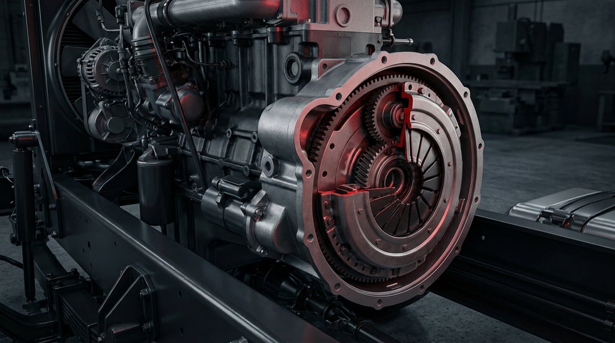
It is one of the most "invisible" components in the field: the thick cast body sitting between the engine and the gearbox, enclosing the clutch and the flywheel. Nobody puts it on a preventive maintenance list — not until a clutch comes out worn on one side, or oil starts dripping from underneath the housing. The flywheel housing (clutch bell housing, bell housing) is not just a cover — it is the reference component that keeps the crankshaft axis and the gearbox input shaft on the same line. Even a misalignment on the order of tenths of a millimetre is paid for by the clutch kit, the release bearing, the input shaft seal and the starter pinion.
E-E-A-T note: This document was prepared by the VADEN technical team, based on field and product experience with heavy commercial vehicle driveline components. The values given here are typical reference ranges; they vary with the engine family, the housing material and the SAE interface class. For exact torque, runout and flatness tolerances, always refer to the vehicle manufacturer's current service manual. Last updated: July 2026.
What Is a Flywheel Housing / Clutch Bell Housing? Function and Operating Principle
The flywheel housing (clutch bell housing) is the load-carrying cast body bolted between the rear face of the engine block and the gearbox case; it encloses the flywheel, the clutch assembly and the starter ring gear, and at the same time determines driveline alignment by centring the gearbox input shaft axis relative to the crankshaft axis.
Although it has no moving parts, it performs three jobs simultaneously. The first is structural: it transfers the weight of the gearbox and the torque reaction into the engine block; on a heavy commercial vehicle this means carrying a mass of several hundred kilograms along with high torsional loads. The second is centring: thanks to the dowels on the face that seats against the block and the spigot (pilot) diameter on which the gearbox lands, the two axes are brought onto the same line. The third is enclosure: the flywheel, the pressure plate, the driven disc and the release bearing all operate inside this body; the starter motor, the speed sensor, the inspection cover and — in most applications — the release mechanism are mounted to it.
On heavy commercial vehicles, housing interfaces are largely designated according to the SAE J617 standard (SAE 1, SAE 2, SAE 3 and so on). The standard defines the bolt circle and the spigot diameter on the block side; the smaller the number, the larger the interface. This allows different gearboxes to be mated to the same engine family.
- Main body (bell): The cast shell joining the block flange to the gearbox flange; it carries the torque reaction and the weight of the gearbox.
- Dowel pins and dowel bores: Position the housing on the block repeatably; they are the true determinant of alignment.
- Gearbox mounting face and spigot diameter: Ensure the input shaft enters the flywheel pilot bearing cleanly.
- Starter motor pocket: Determines the mesh depth and backlash between the starter pinion and the flywheel ring gear.
- Inspection cover and sensor bores: Access window for leak checks; location of the flywheel speed sensor.
- Drain hole: The lower opening through which seal leakage is discharged; it must never be blocked.
- Release mechanism attachments: Fork pivot, hydraulic/pneumatic cylinder bracket, or the concentric cylinder mounting face.
- PTO openings and heat shield elements: Power take-off points, cover gaskets, sheet metal shielding.
Cast iron or aluminium?
Cast iron housings offer high rigidity and good vibration damping; they are still widespread in heavy tractor units and construction applications. Aluminium housings provide a significant weight advantage, but their threads are more sensitive: an M12 thread tightened with excessive torque strips easily, and once bolt preload is lost the joint faces separate. In aluminium, cracks usually start at the corners of the starter pocket and at the bolt bosses; in cast iron, impact-induced fractures are seen mostly in the lower flange area.
Dry housings and wet (oil-bath) applications
In the common truck and bus architecture the clutch is dry; oil finding its way inside the housing is in itself a fault symptom. In some heavy machinery and special-purpose applications, however, an oil-bath clutch or a torque converter is used; there the housing is also an oil volume and the sealing requirement is entirely different. If this distinction is missed during part selection, a component assumed to be "the same housing" arrives with the wrong drain and breather arrangement.
Why alignment (concentricity) matters
The clutch disc slides on the input shaft and is centred between the flywheel and the pressure plate. If the spigot diameter is offset relative to the crankshaft axis, the input shaft is forced into the pilot bearing. The outcome is familiar: one-sided wear on the disc hub, drag during release, early leakage at the input shaft seal, and the complaint "we fitted a new clutch and it did the same again". That is why, in any serious clutch failure, checking the housing faces and runout is not optional — it must be a standard step.
| Application / vehicle class | Typical housing type | Common SAE interface tendency | Prominent damage tendency |
|---|---|---|---|
| Heavy tractor unit (long haul, high torque) | Cast iron, one-piece bell | Large housing, SAE 1 / SAE 0 class | Bolt loosening, flange face separation |
| Distribution truck / medium duty | Aluminium or cast iron | SAE 2 class | Thread stripping in aluminium, starter pocket wear |
| City and coach bus | Predominantly aluminium, heat shielded | SAE 1 – SAE 2 class | Vibration cracking, sensor bore distortion |
| Construction / tipper, off-road use | Cast iron, reinforced flange | SAE 1 class | Stone impact, lower flange fracture, blocked drain |
| Special bodywork with PTO and machinery | Housing with PTO opening or oil bath | Application specific / SAE 2 – SAE 3 | Cover leakage, breather blockage |
Part number verification is essential. The flywheel housing is one of the last components that should ever be chosen "by eye". Even within the same engine family, the bolt circle, spigot diameter, starter pocket angle, sensor bore position, PTO opening and overall depth can differ by year of production. Before ordering, compare the OE number of the removed part, the engine and chassis numbers, the SAE interface class and the mounting side of the starter motor. A depth difference of a few millimetres upsets starter pinion engagement and chews up the flywheel ring gear in short order.
Failure Symptoms and Diagnosis
The flywheel housing does not look like a component that "fails" on its own; its faults usually arrive as complaints about neighbouring parts. The right diagnostic question is this: does this clutch, gearbox or starter complaint originate from the alignment or the integrity of the housing?
| Symptom | Possible Cause | Check / Verification |
|---|---|---|
| Rapidly recurring wear despite a new clutch kit, one-sided wear on the disc | Spigot diameter offset relative to the crankshaft axis; dowel bores gone oval | Measure the radial runout of the spigot diameter and the face runout with a dial indicator; check whether the disc wear pattern is one-sided |
| Metallic rattle from the housing area at pull-away and idle, noise changing with load | Loose flange bolts, cracked or broken bracket; release bearing clearance | With the engine shut down, check bolt torques; open the inspection cover and examine the body for cracks and contact marks |
| Oil dripping from the lower drain hole of the housing | Leaking crankshaft rear seal or gearbox input shaft seal | Distinguish the colour and smell of the oil (engine or gearbox oil); open the cover and observe whether the wetness is at the front or the rear |
| Hard starter engagement, pinion grinding or tooth wear on the flywheel ring gear | Worn/distorted starter pocket, housing of incorrect depth, loose starter bolts | Measure the mesh depth and backlash between the starter pinion and the ring gear; check the flatness of the pocket face |
| Difficult gear changes, clutch not releasing fully | Worn release fork pivot seat, distorted concentric cylinder face | Measure the free movement of the release mechanism and the pivot clearance; check the cylinder mounting face for flatness |
| Unstable speed signal, fault code with performance limitation | Sensor bore distorted or loose; sensor-to-ring gear gap disturbed | Measure the sensor air gap, look for cracks/crushing around the bore, monitor the signal with an oscilloscope |
| Face separation at the gearbox flange, polished marks around bolt holes | Insufficient or excessive torque, repeated removal and refitting, crack initiation | Clean the faces and check flatness with a straightedge and feeler gauge; look for radial marks around the holes |
| Vibration under heavy load, drone varying with engine speed | Loss of rigidity due to cracking; dynamic loss of alignment together with the mounts | Carry out an overall check that also covers the engine and gearbox mounts; correlate the vibration with engine speed and load |
Runout measurement with a dial indicator: the test that ends the argument
When alignment is in doubt, the only objective method is measurement with a dial indicator. Two components are measured: radial runout (the offset of the spigot diameter relative to the crankshaft axis) and axial/face runout (the perpendicularity of the gearbox mounting face to the crankshaft axis). The indicator is attached to the flywheel or the crank flange with a magnetic base and the reading is taken while the crankshaft is turned one full revolution by hand; to keep crankshaft end float out of the measurement, light axial pressure is applied in a constant direction throughout the rotation. If the total indicator reading (TIR) is above the manufacturer's limit, trying to solve the problem by replacing the clutch is a waste of time.
Isolating the source of an oil leak
Oil coming from the housing has two candidates: the crankshaft rear seal at the front, and the gearbox input shaft seal at the rear. In practice the distinction is made by colour and smell; for a definitive answer the inspection cover is removed and the area examined with a light — the direction of the wetness and the spray pattern reveal the source. A blocked crankcase breather can overload the rear seal and cause recurring leaks "when the seal is not at fault"; this point must not be skipped.
Crack detection and face assessment
On a removed housing, cracks are mostly invisible to the naked eye. Once the surface has been thoroughly cleaned, dye penetrant inspection is the most practical method; in critical applications, magnetic particle inspection is preferred for cast iron. The corners of the starter pocket, the bolt bosses, the edges of PTO openings and the lower flange area in particular should be scanned. Even without a crack, a face separation mark is a strong indication that bolt preload has been lost.
Further reading
For a plain-language technical overview of this subject, see the reference article on Wikipedia. Always confirm specific figures and procedures against the vehicle manufacturer service data.
Replacement / Installation Steps
Personal protective equipment and safety: The main risk in this job is weight. On a heavy commercial vehicle the gearbox weighs several hundred kilograms; never support it with improvised arrangements — use a gearbox jack or hoist of adequate capacity together with a safety strap. If the vehicle is to be raised, axle stands are mandatory. Switch off the ignition, isolate the battery master switch, secure the starter circuit; on air systems, drain the reservoirs. Wear a mask against clutch lining dust and never blow the dust away with compressed air. Gloves, safety glasses and steel toe-capped boots are mandatory; if the cab is to be tilted, check the tilt lock.
- Record the diagnosis and secure the vehicle: Write down the runout values, crack findings and the leak source. Then: level ground, parking brake, chocks, battery master switch off; depressurise the air, hydraulic and electrical connections.
- Remove the surrounding components with labelling: Starter motor, speed sensor, release cylinder/fork, harness clips, inspection cover and the heat shield if fitted. Label every connector and union, and take photographs.
- Support and separate the gearbox: Strap the gearbox to the jack, disconnect the propshaft and support brackets, loosen the flange bolts progressively; withdraw it axially without applying side load to the input shaft.
- Remove the clutch assembly and the flywheel: Loosen the pressure plate bolts crosswise and in stages; use an aligning tool so that the disc does not drop. If the flywheel is to be removed, choose a lifting method suited to its weight and protect the crank flange threads.
- Remove the housing and assess the rear seal area: Loosen the bolts in a crosswise sequence and draw the body back axially without forcing the dowel bores. At this stage, always assess the crankshaft rear seal and its carrier if fitted; renewing it while access is open is the right call.
- Clean the block and flange faces: Remove old gasket residue with a non-scoring scraper and eliminate oil and grease traces. Do not use aggressive grinding on aluminium faces. Clean the bolt holes; debris at the bottom of blind holes causes false torque readings.
- Compare the new part one to one: The bolt circle, spigot diameter, overall depth, starter pocket position and angle, sensor bore, drain hole orientation and PTO opening must be identical to the old part. If there is even the smallest difference, do not fit it — verify the reference again.
- Check the dowels and fit the housing: Confirm that the dowel pins are sound and tight in their bores; an ovalised bore will not save the alignment. Seat the body on the dowels, start the bolts by hand and tighten them to the manual torque in stages, crosswise from the centre outwards. If the manufacturer specifies sealant or a gasket, use only the specified type and quantity.
- Measure the alignment after fitting: Taking the crank flange as the reference, re-measure the radial runout of the spigot diameter and the face runout with a dial indicator. If the value is out of limits, remove it and reassess the faces and dowels; do not carry on thinking "it will settle anyway".
- Fit the flywheel, clutch and surrounding components: Fit the flywheel bolts to the manufacturer's sequence and torque (with angle tightening if required). Align the disc with the aligning tool and tighten the pressure plate crosswise and in stages. Pack the release bearing with a light film of grease and fit the starter motor and the sensor with the correct clearance.
- Connect the gearbox and carry out final checks: Seat the gearbox axially without forcing it, never drive the input shaft in with a hammer and never let the unit rest on the input shaft under its own weight. Tighten the flange bolts to torque and reconnect everything. Start the engine and listen at idle, confirm that the clutch releases fully, and after a short road test repeat the leak and torque checks.
Points to Watch (Common Mistakes)
The most expensive mistake: closing it up without measuring the alignment. This entire job is the answer to one question — "are the two axes on the same line?" An assembly carried out without a dial indicator is, at best, down to luck. A brand-new clutch kit fitted while runout is out of limits comes back with the same fault within a few thousand kilometres — and this time it takes the input shaft seal and the pilot bearing with it.
Never let the gearbox hang on the input shaft. This is the second most common mistake in the field. When the jack is lowered while the gearbox is only partly engaged, the entire weight bears on the input shaft and the disc hub; the hub is permanently distorted and the pilot bearing is crushed. The gearbox must remain supported until the flange faces are in full contact and the bolts are tightened.
- Tightening bolts in one pass and in random order: Causes face separation and distortion in a cast body; always tighten crosswise and in stages.
- Excessive torque on an aluminium housing: The number one cause of stripped threads and cracked bosses; use a torque wrench.
- Ignoring the dowel pins: An assembly made with missing, bent or ovalised dowels does not guarantee alignment.
- Blocking the drain hole: Excess sealant blocks the lower drain; the housing collects oil and the lining becomes contaminated.
- Not renewing the crankshaft rear seal while access is open: The most common reason for doing the same job twice; the labour costs many times the price of the seal.
- Not checking starter backlash and sensor gap: A badly seated housing chews up the flywheel ring gear, and a misadjusted sensor generates fault codes that are hard to diagnose.
- Refitting used or single-use bolts: A bolt that has reached its stretch limit will not hold preload.
Technical Values and Check Points
The values below are typical / general reference ranges for heavy commercial vehicle flywheel housing applications. They vary with housing size, material, bolt class and manufacturer; for exact values the service manual is decisive.
| Parameter | Typical reference range | Note |
|---|---|---|
| Spigot diameter radial runout (TIR) | approx. 0.10 – 0.30 mm | Closer to the upper band on large SAE housings; if the limit is exceeded, assess dowels and faces |
| Gearbox mounting face axial runout (TIR) | approx. 0.10 – 0.25 mm | Crankshaft end float must be taken up during measurement |
| Flange face flatness deviation | approx. 0.05 – 0.15 mm | A preliminary check can be made with a straightedge and feeler gauge |
| Starter pinion – flywheel ring gear backlash | approx. 0.3 – 1.0 mm | Application specific; assessed together with mesh depth |
| Speed sensor air gap | approx. 0.5 – 1.5 mm | Varies with sensor type; the manufacturer's value governs |
| Operating temperature inside the housing | approx. 80 – 200 °C | Momentary values at the clutch friction face are higher |
| Condition of the lower drain hole | always open and clean | A blocked drain is the silent cause of oil-contaminated linings |
| Joint | Typical torque range | Warning |
|---|---|---|
| Housing – block bolts (M10) | approx. 45 – 70 Nm | Tighten crosswise, in at least two stages |
| Housing – block bolts (M12) | approx. 85 – 120 Nm | On aluminium housings stay towards the lower band |
| Gearbox – housing flange bolts (M14 – M16) | approx. 150 – 250 Nm | Varies markedly with application class |
| Starter motor mounting bolts | approx. 40 – 70 Nm | Overtightening distorts the pocket face |
| Inspection cover and sheet metal shield bolts | approx. 8 – 25 Nm | Thin sheet metal; tighten without crushing |
| Flywheel bolts | manufacturer's value (usually torque + angle) | Generally single-use; do not reuse |
Field tip: Really clean the faces before measuring. A thin trace of gasket residue or a burr left on the flange produces false runout in the order of 0.10 mm and condemns a perfectly good housing to scrap. Repeat the measurement twice, from different starting angles; if the two readings do not agree, the problem is not in the part but in the set-up.
- Open the inspection cover and check the internal surfaces for oil film, clutch dust sludge and metal swarf.
- Pass a thin wire through the lower drain hole to confirm it is clear; clean it if blocked.
- Look for polishing, crushing and wear steps on the starter pocket mounting face; scan the pocket corners and bolt bosses with penetrant.
- Check the diameter of the dowel pins and their fit in the bores; a pin that comes out easily is suspect.
- Review the engine and gearbox mounts during the same job; a fatigued mount destroys alignment dynamically.
- Re-check the flange bolt torques within the first 500 – 1,000 km after assembly.
Maintenance and Service Life
The flywheel housing is a component dimensioned to last the life of the vehicle; it has no replacement interval. What shortens its life is not wear but three things: incorrect assembly, neglected leaks and impact. With those three under control, the same housing outlives the vehicle; without that control, it ends up as scrap within a few clutch replacements.
- Treat every clutch replacement as an opportunity: Internal cleaning, crack inspection, dowel condition and runout measurement should be a standard part of the clutch job.
- Do not put off leaks: A leaking crankshaft rear seal or input shaft seal contaminates the lining, shortens clutch life and leaves permanent residue inside the body.
- Check the crankcase breather: A blocked breather raises crankcase pressure and overloads the rear seal; the leak returns even after the seal is replaced.
- Keep the drain hole open: It is a few seconds' check during servicing; when skipped, the price is a complete clutch kit.
- Watch driving habits: Slipping the clutch for long periods when pulling away raises the temperature inside the housing considerably; heat fatigues both the lining and the surrounding sealing elements.
- Protect against impact from below: In construction and off-road use, an underbody guard plate largely prevents flange fractures caused by stone impact.
- Assess mounts and supports, and keep records: A fatigued mount produces dynamic loss of alignment; write the measured runout values into the vehicle file and compare them on the next job.
In a well-managed fleet the flywheel housing is almost never on the agenda — and that is proof the job is being done properly. Conversely, if the complaint "the clutch has gone again" keeps repeating, the answer usually lies not in the parts being replaced but in the cast body that carries them.
The flywheel housing is a reference component that is never mentioned again when it is correctly selected and correctly fitted — and that takes every part behind it with it, one by one, when it is not. The VADEN ORIGINAL Flywheel Housing / Clutch Bell Housing product family is held in stock in the catalogue, matched to OE references for heavy commercial vehicle applications; determining the correct reference from your vehicle's engine, chassis and gearbox data — and adding the seals, dowels and bolts to the same list when planning the clutch job — is the shortest route to not doing the same job twice in the field.
Related categories: Flywheel Housing · Flywheel Housing
Related technical guides: Exhaust Manifold: Cracks, Leaks, Replacement & Torque Guide · Engine Cylinder Head Group: Faults, Replacement & Maintenance · Exhaust / Engine Brake: Faults, Replacement & Maintenance Guide · Oil Cooler: Failure Symptoms, Replacement & Maintenance Guide · Truck Oil Pan Group: Faults, Replacement & Maintenance Guide
Application and compatibility: Vehicle compatibility catalogue · Engine compatibility catalogue
Main guide: What Is a Crankshaft? Function, Failure Symptoms and Maintenance
Tags
Frequently Asked Questions
- Are a flywheel housing and a clutch bell housing the same thing?
- Yes, they are different names used in the field for the same part. "Flywheel housing", "clutch bell housing" and simply "bell housing" all describe the cast body between the engine and the gearbox that encloses the flywheel and the clutch. Confusion can arise because some catalogues emphasise the engine side and call it a housing, while others emphasise the gearbox side and call it a bell; verifying with the OE number before ordering is the safest approach.
- There is a crack; can it be repaired by welding?
- The general approach is to avoid weld repair on a load-carrying body that serves as an alignment reference. Welding cast iron requires a special procedure, preheating and controlled cooling; even when it appears successful, thermal distortion can upset the spigot diameter and face flatness. Repair to a non-critical bracket may be possible with expert assessment; where cracks involve the flange, a dowel bore or the spigot diameter, replacing the part is the correct decision.
- I fitted a new clutch but it wore out quickly again; could the housing be the cause?
- Yes; it is one of the most frequently overlooked causes of recurring early clutch failure. If the spigot diameter is offset, the disc is strained on every revolution and wears on one side. Look at the wear pattern on the disc: if the wear is concentrated on one side, or there are polish marks on the hub, misalignment is strongly suspected. A dial indicator runout measurement is needed for a definitive answer.
- Oil is dripping from the lower hole of the housing — which seal is at fault?
- There are two candidates: the crankshaft rear seal and the gearbox input shaft seal. To distinguish them, the inspection cover is opened and the side the wetness comes from is observed; the colour and smell of the oil also help. With crankshaft rear seal leaks, also check the crankcase breather, because a blocked breather destroys the seal over and over again.
- Is it really necessary to drop the gearbox just to replace the housing?
- In practice, yes. As the housing sits between the engine block and the gearbox, access is only possible once the gearbox has been separated. For that reason, when planning the job the most sensible approach — to avoid a second removal — is to assess the clutch kit, release bearing, crankshaft rear seal and input shaft seal at the same time.
- What do numbers such as SAE 1 and SAE 2 mean?
- These are the housing interface dimensions in the SAE J617 standard; they define the bolt circle and the spigot diameter on the block side. The smaller the number, the larger the interface. This standard makes it possible to mate different gearboxes or power units to the same engine; however, a matching interface alone does not guarantee that the part suits the vehicle — depth, starter pocket and sensor position must match as well.
- Is an aluminium housing at a disadvantage compared with cast iron?
- Not in its own application. Aluminium housings provide a weight advantage and are designed with the rigidity calculated for that vehicle. Their disadvantage is low tolerance to service errors: excessive torque, assembly onto a dirty face and forced alignment turn into damage far more quickly in aluminium. With correct torque and clean assembly there is no service life issue.
- How often should I check the housing bolts?
- In normal use no separate interval is required; however, verifying the torques at the first inspection after removal and refitting is recommended. In construction, off-road and high-vibration use, a visual check for loosening and face separation marks at scheduled services is worthwhile. If a new metallic noise is coming from the area, carry out the check without waiting for the service interval.
- How do I measure runout with a dial indicator when alignment is in doubt?
- Measure two values: the radial runout of the spigot diameter relative to the crankshaft axis, and the axial or face runout of the gearbox mounting face. Fix the indicator to the flywheel or crank flange with a magnetic base and read while turning the crankshaft one full revolution by hand. Apply light axial pressure in a constant direction so crankshaft end float does not distort the reading. Above the manufacturer's limit, replacing the clutch solves nothing.
- Why must the lower drain hole of the housing be kept clear?
- Seal leakage is discharged through that hole. If it is blocked, oil collects inside the body, contaminates the clutch lining and the clutch is lost. The usual cause is excess sealant applied during assembly closing the lower drain. Passing a thin wire through it during servicing takes a few seconds; skipping that check can cost a complete clutch kit.
Related Articles

Oil Filter Cap and Housing: Leaks, Cracks and Seal Replacement
Truck engine oil filter cap and housing: why plastic caps crack, O-ring leak causes, bypass valve faults, and correct torque and seal replacement steps.
Piston Rings: Oil Consumption, Compression Loss and Replacement
Ring-related oil consumption and compression loss in truck diesel engines: how rings seal, blow-by and leak-down tests, ring gap and replacement.
Intake Manifold and Intake Pipe: Faults, Diagnosis, Repair
How the intake manifold and charge air pipe work on truck diesel engines, how to spot boost leaks, run a pressure test and fit them leak free.


