Turbo Intake & Exhaust Inlet Pipe: Faults and Replacement
Turbo intake and exhaust inlet pipe faults on trucks: leak symptoms, diagnosis, step-by-step replacement, torque values and maintenance tips from VADEN.
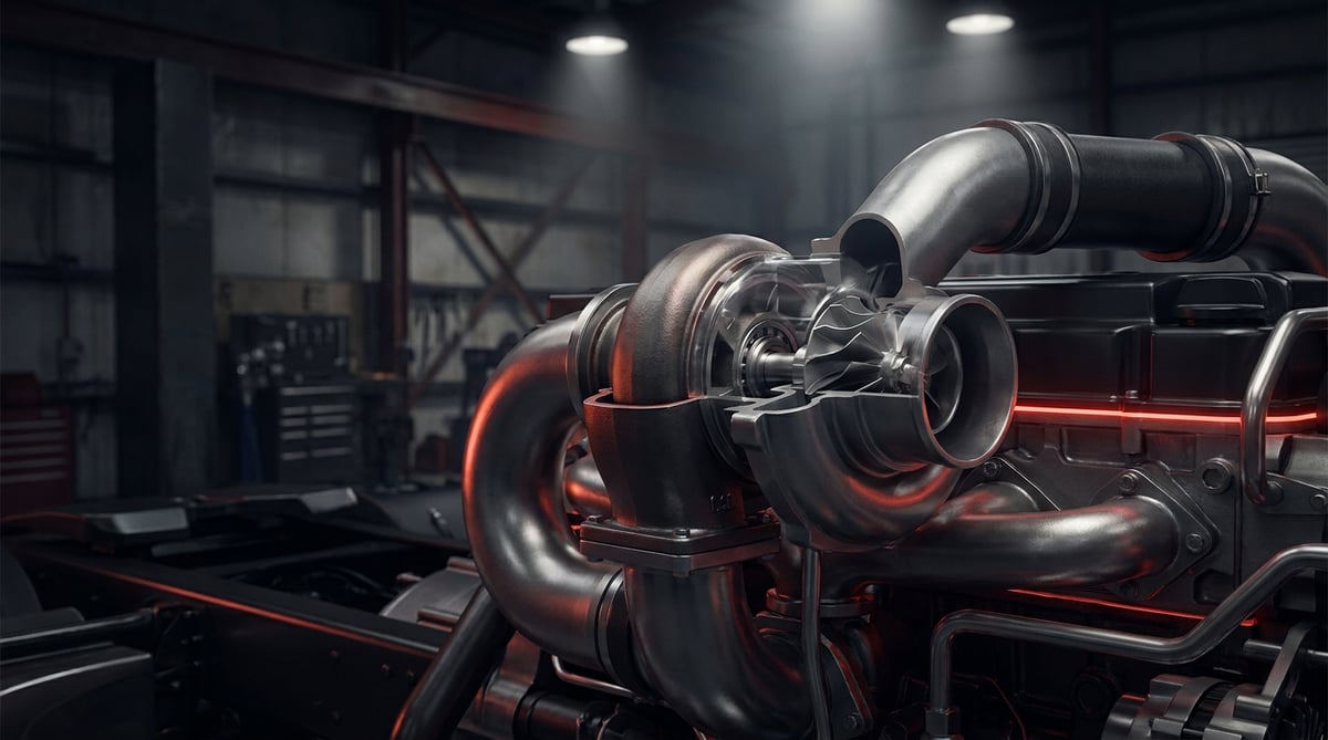
When there is a whistling noise around the turbo of a tractor unit, the vehicle no longer pulls the way it used to under throttle and there are soot marks under the hood, the turbo is usually the first component to be blamed. In the field, however, one of the pipes connected to the turbo is very often behind this picture: either the intake pipe on the compressor side is leaking air, or the exhaust inlet pipe on the turbine side is cracked, its gasket has burnt through or its flange has warped. The turbo is an expensive component; the pipes running to and from it are comparatively cheap, yet a fault in them produces exactly the same symptoms. This guide covers the turbo intake pipe and exhaust inlet (turbo inlet) pipe group on heavy commercial vehicles in plain workshop language: what they do, how they fail, how to tell them apart from other faults, how to replace them correctly and how to extend their service life.
E-E-A-T note: This document was prepared by the VADEN technical team, based on field and manufacturing experience with air and exhaust line products for heavy commercial vehicles. The values given here are typical reference ranges; they vary according to engine family, pipe type and year of manufacture. For exact torque, pressure and temperature values, always refer to the current service manual of the vehicle/engine manufacturer. Last updated: July 2026.
Component sizing is based on the relevant international standard family (ISO/EN/DIN/SAE) and the manufacturer OE specification.What Is a Turbo Intake / Exhaust Inlet Pipe? Function and Operating Principle
The turbo intake pipe is the connecting element that carries clean air from the air filter to the turbo compressor inlet without leakage; the exhaust inlet pipe is the connecting pipe that routes hot gas leaving the exhaust manifold to the turbine inlet of the turbo, working under high temperature and vibration.
The turbo is not a unit that works on its own; it operates at the intersection of four separate lines. On the turbine side, exhaust gas enters and leaves; on the compressor side, clean air is drawn in and delivered under pressure to the intercooler. Each of these lines is connected by its own pipe. The pipe on the intake side works just below atmospheric pressure, that is, under slight vacuum; even the smallest opening there draws unfiltered air inside. The exhaust inlet pipe faces exactly the opposite condition: there is pressurised, very hot gas inside, and a leak to the outside means both power loss and hot gas and soot under the hood.
These two pipes are also mechanically stressed in different ways. The intake pipe usually has a steel, aluminium or composite body with hose and clamp connections at its ends; its typical problem is fatigue cracking and loosening connections. The exhaust inlet pipe, on the other hand, is exposed to a cycle of thermal expansion and contraction: it has one dimension when the engine is cold and lengthens noticeably at full load. For this reason, many applications use a bellows (compensator) type. The bellows absorbs the expansion and the movement of the engine relative to the chassis, protecting the flanges and the turbo housing. Failure of bellows-type pipes usually starts when the bellows can no longer perform its function.
- Pipe body: Steel/aluminium on the intake side, heat-resistant steel or stainless alloy on the exhaust side; any reduction in cross-section directly causes power loss.
- Flanges: The faces bolted to the turbo inlet and to the manifold; their flatness is the key to sealing.
- Bellows / compensator: The flexible section that absorbs thermal expansion and vibration (not present on all types).
- Gasket and sealing element: Metal or graphite gasket on the exhaust side, O-ring or hose bead on the intake side.
- Hoses and clamps: The silicone/rubber part providing the flexible connection in the intake line, and the clamping elements.
- Mounting brackets: Supports that fix the pipe to the engine or chassis; a broken bracket will crack the pipe in a short time.
- Sensor and additional ports: Some pipes have ports for temperature, pressure or an EGR connection.
Compressor side: turbo intake (air inlet) pipe
This is the section between the air filter outlet and the turbo compressor inlet. The pressure here is below atmospheric, so a leak goes inwards rather than outwards. The result is invisible but serious: unfiltered dust reaches the compressor wheel blades directly, wears the blade tips and finishes the turbo prematurely. A small crack in the intake pipe or a loose clamp turns into a turbo bill in the long run.
Turbine side: exhaust inlet (turbo inlet) pipe
This is the section between the exhaust manifold and the turbo turbine inlet. It operates under high temperature, pressurised gas and continuous thermal cycling. A leak here causes a direct loss of power and response because part of the gas driving the turbo is lost; in addition, hot gas escaping from the leak point damages nearby hoses, cables and seals. In some heavy commercial applications, the EGR take-off point is also located on this pipe.
Oil film found inside the pipe in this section does not always point to the turbo; for the possibility of oil carry-over from crankcase ventilation, see the oil separator guide.
The leak sought in this section can just as easily come from where the line begins as from the pipe itself; for leak symptoms on the manifold side, see the exhaust manifold guide.
Bellows (compensator) types and why they became necessary
The engine oscillates on its own mounts, while part of the exhaust line is mounted more rigidly. The resulting difference in movement has to be absorbed somewhere. The bellows-type pipe takes on this task. When the bellows fatigues or stiffens due to soot and corrosion, it can no longer absorb the movement; the stress is then transferred to the flange bolts, the weld seams and, worst of all, to the turbo housing. If there is visible deformation, soot marks or hardening on the bellows, the pipe should be assessed as a whole.
| Pipe type / position | Typical construction | Operating condition | Prominent failure tendency |
|---|---|---|---|
| Turbo intake pipe (filter - compressor) | Steel/aluminium body + hose and clamp | Slight vacuum, close to ambient temperature | Hose cracking, loose clamp, ingestion of unfiltered air |
| Exhaust inlet pipe (manifold - turbine), straight type | Heat-resistant steel, flange at both ends | High temperature, pressurised gas | Flange warping, gasket burn-through, weld cracking |
| Exhaust inlet pipe, bellows type | Flange + metal bellows (compensator) | Thermal expansion and engine oscillation | Bellows fatigue, cracking, hardening |
| Turbo inlet pipe with EGR port | Body with additional flange/port | Soot-laden hot gas | Soot blockage and corrosion around the port |
| Compressor outlet / intercooler connection (adjacent line) | Pipe + silicone hose | Pressurised hot air | Hose tearing, clamp slipping — produces similar symptoms |
Part number verification is essential. Even within the same engine family, pipe length, flange hole spacing, bend angle, the presence of a bellows and the sensor port may vary according to the year of manufacture or the emission level. Before ordering, compare the OE number on the removed part, the vehicle chassis/engine number and the flange geometry. The "it looked similar, we forced it on" approach comes back as a new crack in a short time because of stressed installation.
Failure Symptoms and Diagnosis
Faults in this group are almost always confused with turbo failure. The correct order is this: first verify the sealing of the line, then question the turbo. The table below summarises the symptoms most frequently encountered in the field and the checks that distinguish them.
| Symptom | Possible Cause | Check / Verification |
|---|---|---|
| No power under throttle, does not pull on gradients | Leak in the exhaust inlet pipe; part of the gas feeding the turbine is lost | Clean around the flange and load the engine; look for fresh soot marks and gas blow-by with a light |
| Whistling or hissing noise from the turbo area | Cracked intake pipe, loose clamp or hose separation | Check the connections by hand at idle; block the line and apply a low-pressure leak test |
| Harsh, ticking-like blowing noise from the exhaust area | Flange gasket leaking, bolt loose or missing | Check the bolt torques; look for a dark soot line along the gasket joint |
| Soot marks and blackened surfaces in the engine bay | Hot gas leak; crack in the bellows or weld seam | Clean the surface and, after a short road test, mark the point where the trace reappears |
| Increased fuel consumption and black smoke | Insufficient charge air: intake restriction or a line leak | Read the boost pressure under load; check air filter contamination and intake cross-section |
| Turbo failed again after a short time | Ingress of unfiltered dust or foreign matter from the intake side | Inspect the compressor blade tips of the removed turbo; if there is wear, check the intake line end to end |
| Warning lamp, boost pressure or air mass fault | Deviation between measured and expected values due to a leak | Monitor air mass and boost values in live data, confirm with a line test |
| Leak noise clear when cold, decreasing as it warms up | Micro-crack on the exhaust side that partly closes with thermal expansion | Locate it by listening at the moment of first start-up; inspect without waiting for warm-up |
Leak test: the method that ends the argument
For the intake and charge air line, the most reliable approach is to block the line with suitable adapters and test it at low pressure. When soapy foam is applied, the leak point reveals itself immediately. Do not raise the test pressure above the limit permitted by the manual; otherwise you may damage even a sound hose. On the exhaust side, the most practical method is to clean the surfaces thoroughly, load the engine and then follow the fresh soot trace that forms.
Pipe or turbo? The logic of telling them apart
The order should be: (1) air filter condition and intake restriction, (2) intake pipe and hose connections, (3) exhaust inlet pipe flange and bellows condition, (4) boost pressure measurement, (5) turbo shaft play and wheel inspection. If the turbo shaft play checked by hand is normal, the wheels are clean and there is no oil leak, but there is still no power, suspicion shifts to the pipes and connections. Skipping this sequence and replacing the turbo directly usually results in the vehicle coming back with the same complaint.
Reading soot traces: the leak point writes its own address
An exhaust leak leaves its own evidence. If there is a thin, dark and dry fan-shaped trace around the flange, gas is blowing out from there. If you see a wet trace mixed with oil, the source is different: that points more to a turbo seal or an oil line. Distinguishing whether the trace is dry or oily is the fastest way to get to the right part.
Further reading
For a plain-language technical overview of this subject, see the reference article on Wikipedia. Always confirm specific figures and procedures against the vehicle manufacturer service data.
Replacement / Installation Steps
Personal protective equipment and safety: The exhaust and turbo area stays at high temperature for a long time after the engine is switched off; wait until the engine has cooled down completely before starting work. Use heat-resistant gloves, safety goggles and work clothing. Disconnect the battery isolator and, if the cab is to be tilted, verify the tilt lock. Keep away from open flames when using penetrating spray on seized bolts. Soot dust must not be inhaled; wear a dust mask if necessary. Plug all air and exhaust openings immediately after removal — a single nut or piece of gasket dropped into the turbo inlet will render the turbo completely unusable.
- Complete the diagnostic record: Before deciding on replacement, record the boost pressure measurement, the leak test and a photograph of the leak point. It will be needed for comparison after installation.
- Secure the vehicle: Level ground, parking brake applied, chocks in place, battery isolator off and the engine cooled down.
- Gain access: If cab tilting or removal of a cover/shield is required, follow the manufacturer's procedure. Disconnect and label any hoses, wiring harnesses and sensor connectors that are in the way.
- Mark the position and orientation before removal: Mark the flange orientation, bracket sequence and bellows position. Especially on angled pipes, this step saves considerable time during installation.
- Loosen the bolts gradually and in the correct sequence: The bolts on the exhaust side may be seized due to thermal cycling; apply penetrating spray and let it soak, be patient instead of forcing. A broken bolt makes the job many times bigger.
- Remove the pipe and plug the openings: Immediately close the turbo inlet port, the manifold port and the intake line ends. If you do not have plugs, use clean lint-free material — do not use ordinary rags.
- Clean the mating faces and check flatness: Remove old gasket residue without scratching the surface. Check the flange flatness with a straight edge or square; if there is noticeable warping, even a new pipe will leak.
- Compare the old part with the new part one to one: Length, angle, flange hole spacing, presence of a bellows, sensor port and bracket holes must all match. If there is any difference, do not install it, and verify the reference again.
- Install stress-free with new gaskets and fasteners: A gasket is never reused; on exhaust connections, use the new bolts/nuts specified by the manufacturer or suitably coated fasteners. Do not force the pipe into the holes — it must seat freely.
- Apply the tightening sequence and torque: First fit all bolts by hand and seat the part, then tighten gradually in a crosswise pattern from the centre outwards to the torque given in the manual. Position the clamps correctly on the hose and tighten to the specified torque; overtightening cuts the hose.
- Start, warm up and check: Start the engine and listen for leaks at idle, then bring it up to normal operating temperature. Once the engine has cooled down again, recheck the torque of the exhaust flange bolts and, after a short road test, repeat the leak and boost pressure checks.
Points to Watch Out For (Common Mistakes)
The most expensive mistake: dropping foreign matter into the turbo port. A nut, a piece of gasket or a broken clamp end that falls in while the intake or exhaust port is open will turn the turbo wheels into scrap within seconds. Plug every opening at the moment of removal and inspect the inside of the line with a torch before installation.
Do not carry out stressed installation. Forcing the pipe with a lever to line it up with the holes leaves permanent stress once the bolts are tightened. This stress shows up as a crack in the weld seam or the bellows during the first thermal cycles. If the pipe does not seat without force, there is a wrong reference part, a warped flange or a broken bracket involved.
- Reusing the gasket: A gasket that has been crushed once will leak on the second installation; renew it at every removal.
- Ignoring a broken or missing bracket: An unsupported pipe carries all the vibration through the flange and the weld, and cracks in a short time.
- Applying excessive torque: It warps the flange and strips the thread. Use a torque wrench and do not break the crosswise sequence.
- Breaking a seized bolt by forcing it: Letting penetrating spray soak is always faster than extracting a broken bolt.
- Leaving the intake hose in its aged condition: A hardened, cracked hose should be renewed together with the new pipe.
- Tightening the clamp in the wrong position: A clamp that does not sit on the bead or shoulder of the hose will slip under pressure.
- Skipping the air filter: A blocked filter increases intake vacuum and quickly exposes the weak point in the line.
- Not rechecking torque after thermal cycling: On exhaust connections, a check after the first warm-up prevents the majority of leaks from the outset.
- Only replacing the pipe without looking for the root cause: If the pipe keeps cracking in the same place, the real cause is vibration, a fatigued mount or incorrect line alignment.
Technical Values and Inspection Points
The values below are typical / general reference ranges for turbo air and exhaust lines on heavy commercial vehicles. They vary according to engine family, emission level and manufacturer; the service manual is definitive for exact values.
| Parameter | Typical reference range | Note |
|---|---|---|
| Charge (boost) pressure, full load | approximately 1.5 – 3.0 bar absolute (≈ 22 – 44 psi) | Varies by engine family; staying below the expected value under load indicates a leak or restriction |
| Intake / charge air line leak test pressure | approximately 0.5 – 1.5 bar (do not exceed the manual limit) | High test pressure can damage even a sound hose |
| Air filter intake restriction (vacuum) warning level | typically around 50 – 75 mbar | If the vehicle has a restriction indicator, take that as the reference; as restriction increases, the pipe is stressed too |
| Turbo inlet (exhaust) gas temperature | approximately 500 – 750 °C band; peak values may be higher | Material and gasket selection is based on this temperature |
| Compressor outlet air temperature (before intercooler) | approximately 120 – 200 °C | Decisive in the selection of the intake/charge air hose |
| Flange face flatness tolerance | manufacturer value; generally in the order of tenths of a millimetre | With noticeable warping, the pipe or manifold must be renewed |
| Visual inspection interval | at every general service and at every turbo intervention | Soot traces and bellows condition must always be checked |
| Connection point | Typical torque range | Warning |
|---|---|---|
| Exhaust inlet pipe flange bolt (M8) | approximately 20 – 30 Nm | Tighten crosswise and gradually; recheck after thermal cycling |
| Exhaust inlet pipe flange bolt (M10) | approximately 40 – 60 Nm | Use of new bolts/nuts is recommended |
| Turbo inlet flange nuts | manufacturer value | Excessive torque must not be applied to the turbo housing |
| Intake line hose clamp | approximately 5 – 12 Nm | Overtightening cuts the hose; the clamp position must be correct |
| Pipe support bracket bolt (M8) | approximately 20 – 25 Nm | The bracket must first seat freely, then be tightened |
Field tip: With a suspected leak, clean around the flange until you have a completely dry, trace-free surface, then take the vehicle out for a short loaded run. The fresh soot fan that forms by the time you return points to the leak like an address. For intake leaks that cannot be found visually, a pressurised leak test is the only definitive method.
- Check whether there is crushing, cracking, soot marks or hardening on the bellows.
- Check that all flange bolts are in place and tight, and that none are missing.
- Check the intake hoses for cracking and hardening by bending them by hand.
- Verify that the pipe support brackets are sound and fully fitted.
- If there is wear on the turbo compressor blade tips, check the intake line end to end.
- Check the air filter and the restriction indicator; if restriction is high, the line is under strain too.
- Recheck the connection torques within the first 500 – 1,000 km after fitting a new pipe.
Maintenance and Service Life
Turbo intake and exhaust inlet pipes are long-lasting components when they are installed correctly and their supports are sound. What shortens their life is almost always three things: stressed installation, a missing or broken bracket, and uncontrolled vibration. When neglected gaskets and bolts left loose are added to these, even a perfectly sound pipe will crack far earlier than expected.
- Carry out a visual inspection at every general service: The flange area, weld seams and bellows section can be assessed with a few minutes of looking.
- Do not neglect the engine mounts: A fatigued mount increases the oscillation of the engine and transfers part of the load to the exhaust line.
- Keep to the air filter interval: A restricted filter increases the vacuum on the intake side and accelerates the exposure of the weak point.
- Renew the gasket and bolts as a set: When changing the pipe, the gasket, bolts/nuts and, if necessary, the hose and clamp should be renewed together.
- Assess the pipes during any turbo intervention: Inspecting the pipes while the turbo is removed prevents a second loss of workshop time.
- Record soot and oil traces: A trace that keeps recurring at the same point is a sign of a problem that has not been closed out.
- Make the post-thermal-cycle torque check routine: Especially on a new installation, this check eliminates the majority of leaks from the outset.
- Do not shut the engine down abruptly: Stopping the engine immediately after loaded operation creates a harsh thermal shock in the exhaust line; the short idle cool-down period recommended in the manual is good for both the turbo and the pipes.
In practice, on a well-maintained fleet vehicle, these pipes give a service life close to the long maintenance intervals of the engine. By contrast, on a vehicle with fatigued mounts, missing brackets and one that is patched up with the same gasket at every intervention, the same part gives up much earlier. In other words, the answer to the question "how many kilometres does a pipe last" lies far more in installation quality and line support than in mileage.
Behind a loss of power in the turbo area there is usually not an expensive failure, but a line leak that has not been diagnosed correctly. The VADEN ORIGINAL Turbo Intake / Exhaust Inlet Pipe product family is held in stock in the catalogue, matched to OE references for heavy commercial vehicle applications; determining the correct reference using your vehicle's engine and chassis details and planning the gaskets and fasteners together with it means a job that is finished in a single visit in the field.
Related categories: Pipe · Intake Pipe
Related technical guides: Exhaust Flex Pipe: Faults, Replacement and Maintenance Guide
Application and compatibility: Vehicle compatibility catalogue · Engine compatibility catalogue
Main guide: What Is an EGR Valve? Failure Symptoms and Cleaning (Heavy Commercial Vehicles)
Tags
Frequently Asked Questions
- What happens if the turbo intake pipe leaks?
- A leak on the intake side allows unfiltered air to enter the turbo directly. In the short term this means power loss and a whistling noise; in the long term, wear on the compressor blades and turbo damage. That is why even a small crack in the intake line should not be postponed.
- How do I know if the exhaust inlet pipe has cracked?
- The clearest signs are a harsh blowing noise heard on a cold start, dry soot traces around the flange or weld, power loss and blackening in the engine bay. The most practical method is to clean the surface and, after a short loaded drive, see where the trace reappears.
- Is the problem the turbo or the pipe? How can they be told apart?
- If turbo shaft play is normal, there is no wheel damage and no oil leak but boost pressure is low, suspicion shifts to the line. A leak test on the intake side and following the soot traces on the exhaust side clarify the distinction. Replacing the turbo without ruling out the pipes usually results in the same complaint coming back.
- Is welding a cracked pipe a solution?
- It may be a temporary roadside fix but it is not permanent. On a pipe that operates under thermal cycling, the welded area creates a new weak point and it usually cracks again next to the seam after a short time. On bellows types, repairing the bellows is not practically possible; the part must be renewed.
- Do I have to change the gasket and bolts as well when replacing the pipe?
- The gasket must definitely be renewed; a gasket that has been crushed once will leak on the second installation. For exhaust bolts, using new bolts/nuts is the safest route because of thermal cycling and corrosion. If the manufacturer specifies single-use fasteners, this must be followed.
- I fitted a new pipe but there is still no power, why?
- The most common causes are: a leak continuing at another point in the line (intercooler hose, compressor outlet), a blocked air filter, a dirty or damaged turbo, an incorrect reference part, and a new micro-leak caused by stressed installation. Eliminate these points in order and confirm by measuring boost pressure.
- What is the difference between a bellows pipe and a straight pipe?
- The bellows type absorbs thermal expansion and engine movement, protecting the flanges and the turbo housing. If your vehicle uses a bellows type, fitting a straight pipe in its place is not correct; since the movement cannot be absorbed, the stress is transferred directly to the turbo and the manifold.
- The pipe keeps cracking in the same place, what could be the reason?
- A recurring crack almost always points to a mechanical root cause: a broken or missing support bracket, a fatigued engine mount, a warped flange face or stressed installation. Instead of replacing the part again and again, the support and alignment of the line must be checked.
- Why must the open ports be plugged straight away once the pipe is removed?
- Because the most expensive mistake on this job is dropping foreign matter into the turbo port. A nut, a piece of gasket or a broken clamp end falling into an open intake or exhaust port turns the turbo wheels into scrap within seconds. Close the turbo inlet, the manifold port and the intake line ends at the moment of removal, use clean lint-free material if you have no plugs, and inspect the line inside with a torch before fitting.
- When should I recheck the torque after fitting a new pipe?
- Twice. First, start the engine and bring it to normal operating temperature; once it has cooled down again, recheck the torque of the exhaust flange bolts and repeat the leak and boost pressure checks after a short road test. Second, recheck the connection torques within the first 500 – 1,000 km. This post-thermal-cycle check prevents the majority of leaks, and the service manual is definitive for the exact torque figure.
Related Articles

DPF (Diesel Particulate Filter) Guide: Symptoms & Cleaning
Learn what a DPF is, how passive and active regeneration work, warning signs of clogging, and safe cleaning methods for heavy commercial diesel trucks.
Exhaust Flex Pipe: Faults, Replacement and Maintenance Guide
On a truck a collapsed exhaust flex pipe strains the whole line from turbo to DPF: how the bellows absorbs engine movement, fault signs and replacement.
What Is an Exhaust Manifold? Leak Symptoms and Causes
What is an exhaust manifold and how does it work? Leak symptoms, crack causes, turbo impact and diagnosis steps for heavy-duty trucks.


