Steering Drag Link & Tie Rod: Faults, Replacement, Care
On trucks, steering play usually starts at the drag link and tie rod ball joints, not the box: wear testing, safe replacement and toe alignment afterwards.
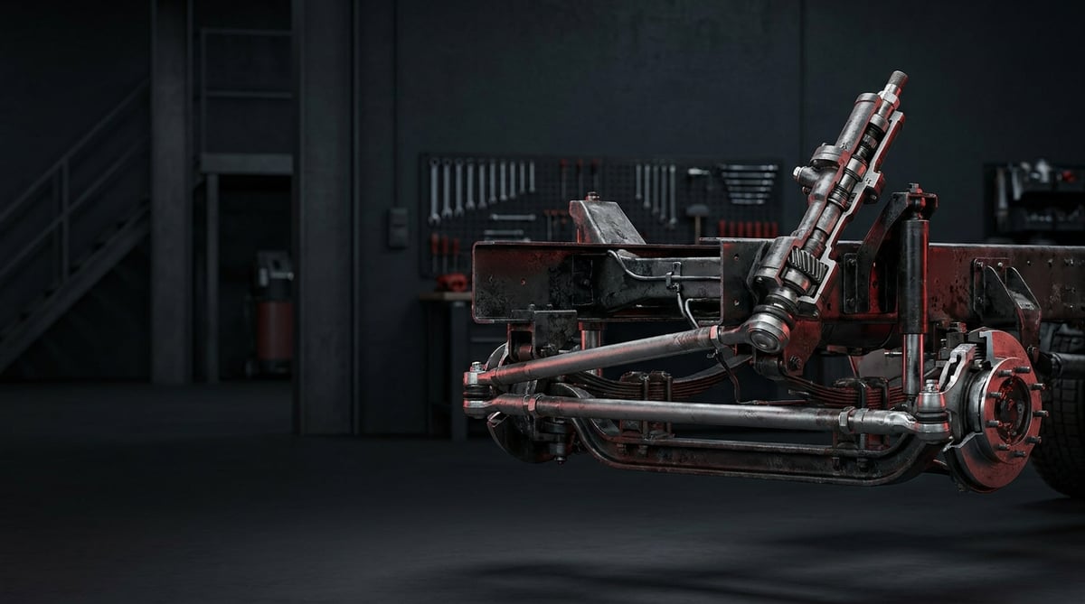
That "one finger of play" felt in a tractor unit's steering wheel usually does not come from the steering box itself, but from the jointed linkage rods between the box output and the wheel. On heavy commercial vehicles, the steering drag link and the tie rod are the connecting elements that physically carry the motion the driver generates at the steering wheel to the front axle and the wheels. On rough ground, the impact of dozens of tonnes of load and the direction-changing forces of manoeuvring are absorbed by these two rods and the ball joints at their ends. When they wear, the vehicle does not fail suddenly; first steering free play and knocking appear, then wandering on the road and irregular tyre wear. This guide covers the operation of the drag link and tie rod system, correct diagnosis of free play, replacement practice and front-end alignment discipline, in the context of OE steering systems (ZF/TRW type) and in the light of the vehicle manufacturer's service specifications.
What Is a Steering Drag Link / Tie Rod? Function and Operating Principle
The steering drag link and tie rod are steel connecting rods with ball joints at their ends that transmit the motion coming from the steering box to the wheels and keep the two front wheels turning parallel to each other.
The steering chain of a heavy commercial vehicle works as follows: the driver turns the steering wheel, the steering column carries the motion to the hydraulically assisted steering box, and the pitman arm at the box output swings. This swing is transferred by the longitudinally mounted drag link to the steering arm of the front wheel on the box side, and that wheel turns — on left-hand drive vehicles this is the left side, on right-hand drive applications the right. The transversely mounted tie rod connects the left and right steering arms to each other; when the wheel on the box side turns, it pulls the opposite wheel along in the same geometry. In this way a single box output steers both wheels in a coordinated manner.
One point of terminology that is frequently confused in the field should be clarified here: the arm to which the drag link and tie rod attach is not a "hub arm". The hub is the part that rotates with the wheel and carries the bearings; the steering rods attach not to the hub but to the steering arm, which is bolted or forged to the axle end / steering knuckle. This guide uses the technically correct term "steering arm".
The main elements that make up the system are:
- Rod body (bar/tube): Forged steel or thick-walled steel tube. Dimensioned to withstand compressive, tensile and bending loads.
- Ball joint: The spherical joint with a tapered pin at the ends of the rod. It accommodates the angular movement required both for steering and for axle articulation. The vast majority of wear occurs here.
- Tapered pin and nut: The tapered fit that locks the joint to the steering arm or pitman arm; it is usually secured with a castle nut and split pin, or with a self-locking nut.
- Dust boot: The elastomer sleeve that retains the joint grease and keeps water and dust out. It should not be confused with a seal; the boot is a flexible cover, while a seal is a separate sealing element. Tearing of the boot is the most common starting point of failure.
- Grease nipple (where fitted): On serviceable types, the nipple through which grease is applied periodically. Sealed-for-life types are produced without a nipple.
- Adjusting clamps and opposite-hand threaded ends (on the tie rod): Thanks to the right/left-hand threads at the two ends of the tie rod tube, the length — and therefore the toe setting — is adjusted by rotating the tube; the clamps lock this setting.
The Difference Between the Drag Link and the Tie Rod
Although both are jointed rods, their functions differ. The drag link carries the steering command from the box to the steering arm; when it wears, dead play at the wheel and delayed response occur. The tie rod maintains the geometric relationship between the two wheels; when it wears, the alignment drifts, the vehicle wanders and the tyres wear irregularly. This distinction guides diagnosis: if there is only steering play, the drag link and box side are examined first; if there is tyre wear, the tie rod side is examined first.
Why Do Ball Joints Wear?
Inside a ball joint, a steel ball runs on a film of grease within a plastic or metal seat. Three factors determine its life: continuity of the grease film, sealing of the boot and impact loading. The moment the boot tears, water, salt and dust get inside; the grease is washed out, the seat wears and play grows rapidly. That is why in practice a joint does not "fatigue and break" — it develops play first — and if that play goes unnoticed, hammering begins in the tapered pin seat.
Twin-Steer Axles (8x4 and Heavy Construction Vehicles)
On tractors and trucks with a single front axle, the steering chain consists of one drag link and one tie rod. However, on twin-steer vehicles such as 8x4 tractors, heavy construction and crane chassis, there is a second steered axle, a relay arm driving that axle, and a second drag link with a second tie rod attached to it. The second axle takes its motion from the first axle through its own linkage chain and works with its own geometry.
The diagnostic implication is clear: a single amount of play felt at the steering wheel may in fact originate from a joint on either axle, and the individual amounts of play add together. For this reason, on twin-steer vehicles the play survey must be carried out separately for both axles; the relay arm bearing and the joints of the second axle must be inspected one by one, just as much as the tie rod and drag link joints of the first axle. Checking only the front axle and replacing parts is the most common cause of wasted service work on twin-steer vehicles. Alignment must also be set separately for both axles, and the coordination between axles must be checked in the sequence specified by the manufacturer.
Type Comparison
| Feature | Steering Drag Link | Tie Rod / Track Rod |
|---|---|---|
| Layout | Longitudinal (box output - steering arm on the box side) | Transverse (left steering arm - right steering arm) |
| Primary function | Transmitting the steering command | Keeping both wheels parallel, holding the toe setting |
| First symptom of wear | Steering free play, delayed response, knocking | Wandering on the road, irregular tyre wear, vibration |
| Length adjustment | Adjustable on some types (varies by vehicle) | Generally adjustable — the toe setting is made here |
| Adjustment after replacement | Steering wheel centre check | Toe alignment mandatory |
| Typical load character | Continuous push-pull, box reaction | Tensile load + road impact |
OE Context: The Steering Box Family Determines the Part Dimensions
On heavy commercial vehicles, the dimensions of the drag link are determined not by the "vehicle make" alone, but by the steering box family used on that vehicle. ZF servocom type and TRW type hydraulically assisted boxes define the position of the pitman arm on the chassis, its swing arc and its output angle differently; when this geometry changes, the overall length of the drag link, the distance between joint centres, the tapered pin size and the working angle of the joint change as well. Two rods that look identical cannot be interchanged simply because the box family differs. Manufacturers such as Mercedes, MAN, DAF, Volvo, Scania, Renault and Iveco define separate OE numbers even within the same model family, according to axle type, wheelbase, chassis height and the number of steered axles. For this reason the correct part must be selected not from the model name, but from the vehicle chassis number or from the OE number on the old part.
For the gear assembly at the centre of this chain, its faults, play adjustment and replacement, see our truck steering gear box guide; this article covers the linkage after the box.
Failure Symptoms and Diagnosis
Failure of steering linkage elements progresses gradually, and its symptoms are easily confused with faults in the suspension, wheel bearing, king pin, steering damper or steering box. The table below is a quick reference for field diagnosis; the distinguishing checks are detailed immediately afterwards.
| Symptom | Possible Cause | Check / Verification |
|---|---|---|
| Increasing dead play at the steering wheel | Wear in the drag link joint, play at the box connection | Two-person "dry-park" test: the joints are watched by hand/eye while the wheel is rocked left and right |
| Knocking/rattling from the front axle area on rough ground | Joint play, loose tapered pin nut | Axial load is applied to the rod with a pry bar and play is sought; nut and split pin checked |
| Vehicle wanders on a straight road, constant correction needed | Tie rod joint wear, drifted toe setting | Toe measurement; radial/axial play test at the tie rod ends |
| One-directional feathering / inner-outer edge wear on the front tyres | Toe out of specification, incorrect tie rod length | Reading the tyre wear pattern + toe measurement |
| Torn joint boot, grease leaked out or dried up | Boot damage, water/dust ingress | Visual inspection; if the boot is torn, the joint's life is effectively over |
| Steering pulls to the left/right under braking | Play in the joints combined with brake imbalance | Mechanical play is eliminated first, then brake balance is assessed |
| Steering vibration at a certain speed (shimmy) | Joint play combined with balance/geometry issues | Play test, tyre balance and axle geometry assessed together |
| Persistent steering vibration at a certain speed | Dead/leaking steering damper, together with joint play | Inspection for oil leakage and loss of damping in the damper |
| Source of play cannot be found on a twin-steer vehicle | Play on the second steered axle or on the relay arm side | The joints of both axles and the relay arm bearing are surveyed separately |
Play Test: The Correct Method
The most reliable method is the dry-park test carried out with the engine running (hydraulic assistance active) and the wheels on the ground: one person rocks the steering wheel left and right through small angles while a second person observes each joint from a safe distance. On a sound joint, the rod and the pin move as a single piece; if there is play, delay, jolting or visible movement occurs in the pin seat. The pry bar test performed with the vehicle raised provides additional confirmation: noticeable movement felt when axial load is applied to the rod is a defect. During the test, hands and feet must not be placed between moving rods.
Isolating the Source: Joint, King Pin or Hub?
Play coming from the front axle is not always tie rod related. If there is movement when the wheel is rocked in the 12–6 o'clock direction, suspicion points to the king pin or the wheel bearing; if there is movement when rocked in the 3–9 o'clock direction, suspicion points to the tie rod/drag link joints. Having one person rock the wheel while the other looks directly at the joint, steering arm and king pin area prevents a sound part from being replaced needlessly.
Ruling Out the Steering Damper
The component most often overlooked in play and shimmy complaints is the steering damper. The damper does not create play; its job is to damp the conversion of road-induced excitation into oscillation in the steering chain. When damping is lost, a small amount of play in the joints that would not produce a complaint on its own turns into persistent vibration within a certain speed band. For this reason, a damper whose body shows oil leakage, which gives no noticeable resistance when compressed by hand, or whose mounting bushes are crushed, must be assessed together with joint play. Suppressing the vibration by replacing only the damper is misleading: the underlying joint play is concealed, not eliminated.
Working Backwards from the Tyre Wear Pattern
The wear pattern on the front tyres often speaks before the measuring equipment does. Rapid one-sided wear on the inner or outer shoulder and a feathered pattern that feels rough in one direction when swept by hand are the classic signs of a toe setting out of specification. In this case, simply turning the tyres is not a solution: joint play must be eliminated first, then the toe must be reset.
Further reading
For a plain-language technical overview of this subject, see the reference article on Wikipedia. Always confirm specific figures and procedures against the vehicle manufacturer service data.
Replacement / Installation Steps
The following sequence is general good practice on heavy diesel vehicles. For torque, disassembly sequence and securing element types specific to the vehicle/axle type, the manufacturer's service manual must always be followed.
- Prepare the vehicle and set the wheels straight: Stop the engine, leave the steering in the straight-ahead position and mark the steering wheel position. This mark will be your reference for the centre check after assembly.
- Measure and document the old part: Before removal, measure the distance between joint centres and note or photograph the position of the adjusting clamps and the number of turns on the thread. Setting the new part to this dimension makes the initial toe adjustment easier.
- Remove the securing element: Remove the split pin (it is not reused) or identify the self-locking nut. When undoing the nut, apply counter-pressure to the taper area if needed so that the pin does not rotate.
- Separate the tapered pin with the correct tool: Use a ball joint separator (puller) of the appropriate size. Do not strike the steering arm, pitman arm or boot with a hammer; the impact widens the taper seat and permanently ruins the neighbouring part and the seating of the new joint. Leaving the nut on a few threads instead of removing it completely prevents the part from dropping when the pin releases.
- Remove the rod, clean and inspect the seats: Free the taper seats of rust, paint and grease residue; a dirty seat does not seat fully and works loose in a short time. If there is ovalling, cracking or hammering marks in the taper bore, replacing the rod alone is not enough — the steering arm / pitman arm must also be assessed. Take this opportunity to check king pin and wheel bearing play.
- Set the new rod to the old dimension: On adjustable types, bring the length of the new rod to the old value you measured; make sure the thread engagement depth at both ends is equal and sufficient. The minimum engagement mark on the thread must not remain outside.
- Seat the joints: Insert the tapered pins into their seats and verify that the boots are fully seated and not folded. Check the angular freedom of movement of the joints, the assembly orientation, and that the rod does not contact the chassis or tyre.
- Tighten the nuts to the manufacturer's torque: Tighten the tapered pin nuts progressively to the manufacturer's value. On applications using a castle nut, if the split pin hole is not aligned after torque has been reached, align it by tightening slightly to the next slot, not by loosening the nut; then always fit a new split pin. Self-locking nuts are single-use.
- Position and tighten the clamps correctly: Position the adjusting clamps at the angle specified by the manufacturer relative to the slot area on the tube; tighten the clamp bolts to the specified torque. An incorrectly positioned clamp can create the start of a crack at the tube end.
- Apply grease and check the boots: On types with grease nipples, lubricate with suitable grease until the boot swells slightly; do not pump enough to burst the boot. Sealed (lubricated-for-life) types are not greased.
- Have the toe alignment set and carry out a road test: When a tie rod or an adjustable drag link is replaced, toe alignment is mandatory. After adjustment, verify that the steering wheel is centred, try full left and full right lock in a safe area, then carry out a road test. After the first 50–100 km, recheck nut torque and split pins.
Ball Joint Separator Types and Correct Selection
The method used to separate the tapered pin is the single step that determines the quality of this job, and the separator type must be chosen accordingly. Pickle fork type separators are driven between two surfaces and forced with a hammer or air hammer; they are fast but almost always cut the boot and destroy the joint. For this reason they should be used only on joints that are already being scrapped and will not be reused. Screw-type (bolted) pullers apply axial, controlled force to the pin; because they protect the boot and the taper seat, they are the standard choice for jobs where the removed part will be reused or where the neighbouring part (steering arm, pitman arm) will stay in place. Hydraulic separators are used on heavy axle applications, on large taper sizes and on seized pins where a screw puller is not enough; because they apply force progressively and repeatably, they eliminate impact risk entirely.
Whatever the type, two rules do not change: the jaw opening and capacity of the separator must suit the taper size of the joint, and when the separator is positioned the force must act directly along the pin axis. A puller of the wrong size applies force to the rod at an angle and can oval the taper seat — producing the same damage as a hammer blow, only slowly. It must not be forgotten that the pin can fly out when tension is released during separation, so the nut should be left on a few threads.
Points to Watch (Common Mistakes)
Most of the mistakes made with this group occur not at the moment of assembly but immediately before and after it: the wrong separation method, skipped alignment and reused securing elements.
- Replacing only the end that has play: The opposite end of the same age usually develops the same fault shortly afterwards; assessment on an axle basis is more economical.
- Fitting the boot crushed or folded: Even on a new part, a folded boot tears within the first few months and ends the joint's life from the outset.
- Neglecting thread engagement depth: If one end is wound too far out during adjustment, engagement decreases; this creates a risk of failure under load.
- Checking only one axle on a twin-steer vehicle: When the second steered axle and the relay arm are not surveyed, the play appears to be eliminated but the complaint persists.
- Not looking for the root cause: Behind a joint that wears early there is usually a torn boot, overloading or disturbed axle geometry; if the root cause is not addressed, the new part will also be consumed early.
- Tightening "by feel" instead of with a torque wrench: With this group, both under- and over-torque are risky; excessive torque strains the taper and the pin, insufficient torque leads to loosening.
Technical Values and Check Points
The values below are typical/general references for heavy commercial vehicles in general; actual figures vary significantly according to vehicle, axle type, taper size and load class. For model-specific values, the manufacturer's service data is definitive.
| Parameter | Typical Range (general reference) | Note |
|---|---|---|
| Acceptable play in the joint | The acceptance criterion is behavioural rather than numerical: the joint and the pin must move as one piece; free movement felt by hand or with a pry bar is a defect. Where a numerical limit exists, it is taken from the manufacturer's service data. | The limit value is set by the manufacturer; inspection criteria vary by country |
| Total toe-in | As a general reference, approximately 0–4 mm (depending on vehicle and axle type) | The exact value is taken from manufacturer data; it directly determines tyre life |
| Boot operating temperature range | Approximately -40 °C to +110/120 °C | Varies by material type; take care where mounted close to exhaust/brake heat |
| Recommended grease class | Generally NLGI 2, EP-additised lithium/lithium complex type | The manufacturer may require a different specification |
| Greasing interval (nipple type) | As a general reference, at periodic service or approximately every 10,000–20,000 km | The interval is shortened in heavy off-road/construction use |
| First check after installation | Torque and securing element check after the first ~50–100 km | Against the possibility of loosening after bedding in |
Typical Torque References (General)
The values below are general references that only give an idea of magnitude; for actual torque always use the vehicle service manual.
| Connection | Typical Range (general reference) | Note |
|---|---|---|
| Small/medium taper joint nut (approximately M16–M20) | ~120–250 Nm | On a castle nut it is tightened further for split pin alignment, never loosened |
| Large taper joint nut (approximately M22–M24 and above) | ~250–400 Nm | Heavy axle applications; the value varies markedly by manufacturer |
| Tie rod adjusting clamp bolt | ~40–80 Nm | Clamp position is set according to the manufacturer's instructions |
| Pitman arm connection | Manufacturer value governs | Mostly model-specific and requires high torque |
Field check points:
- Are all joint boots intact, free of tears and correctly seated?
- Are the tapered pin nuts at torque, and are the split pins new and correctly bent?
- Are the adjusting clamps in the correct position and tight; is the thread engagement depth sufficient?
- Is the steering wheel centred when running straight ahead?
- Is there sufficient clearance between the rod and the tyre/chassis at full left and full right lock?
- On a twin-steer vehicle, have the second axle and the relay arm also been checked?
- Is there oil leakage or loss of damping in the steering damper?
- Has the toe measurement been carried out and recorded?
Maintenance and Service Life
The steering drag link and tie rod are parts replaced according to condition, not according to a calendar. What determines their life is not mileage but the integrity of the boot, greasing discipline, road conditions and loading habits.
- Carry out a visual inspection at every periodic service: A torn boot, leaked grease, rust streaks and a loose nut can be spotted in five minutes; all are early warnings.
- Do not neglect lubrication on nipple types: Grease is both a lubricant and a dirt barrier; new grease that pushes the old grease out also expels water that has crept in.
- Do not put a torn boot on the "we'll look at it later" list: A torn boot starts the countdown for the joint; early intervention is cheaper than complete replacement.
- Use the tyre wear pattern as a maintenance indicator: Irregular wear tells you about geometry and play before you even reach the measuring equipment.
- Assess on an axle basis: Replacing parts of the same age together avoids a second workshop visit and a second alignment charge.
- Check the steering damper during the same service round: Loss of damping produces vibration complaints even with sound joints and leads to unnecessary part replacement.
- Review loading and driving habits: Overloading, mounting kerbs and hitting potholes at speed directly shorten joint life.
With this discipline, steering linkage elements deliver a predictable service life, and failure announces itself in advance through traceable play symptoms rather than sudden breakage. Planned replacement is always cheaper, both in terms of safety and of tyre cost.
The lasting method in steering drag link and tie rod selection is to use three pieces of data together: the OE number, the taper size and the overall length between joint centres. When these three match, the part fits the vehicle's steering geometry from the outset; when they do not, even the highest quality part is the wrong part. For fleets and workshops that encounter different steering boxes and axle types within the same model family, checking these three values against the vehicle chassis number prevents the wrong part from entering the workshop in the first place. The VADEN steering catalogue covers the hydraulic steering pump and steering box groups, and offers a wide reference list on the air brake, disc brake caliper and air compressor side.
The steering drag link and tie rod are safety-critical parts that directly carry the steering safety of a heavy commercial vehicle; material quality, forged construction, joint seat tolerance and boot durability determine both driving safety and the service interval. A replacement matched to OE-equivalent geometry, taper size and durability, used together with the diagnostic, installation and alignment practices in this guide, delivers safe and predictable steering performance. On the VADEN side, the steering range covers hydraulic steering pumps and steering boxes, while the air brake, disc brake caliper and air compressor groups serve the truck, tractor, bus and trailer applications described here.
Related categories: Actuating Lever · Repair Kit
Related technical guides: Hydraulic Steering Pump: Failure, Replacement & Care Guide
Application and compatibility: Vehicle compatibility catalogue · Engine compatibility catalogue
Main guide: Power Steering Pump Failure Symptoms: What to Watch for in Heavy-Duty Commercial Vehicles
Tags
Frequently Asked Questions
- What is the difference between a tie rod and a ball joint?
- The tie rod is the complete bar connecting the two steering arms to each other; the ball joint is the spherical joint at the ends of that bar. In some applications the joint can be replaced separately, whereas on heavy commercial vehicles it is usually the complete rod with integrated joints, or a complete jointed end, that is replaced. Which arrangement applies is determined by vehicle and axle type; part number verification clarifies this distinction.
- What happens when the steering drag link fails?
- The first symptom is increasing dead play at the steering wheel and the command reaching the wheel with a delay. Knocking is heard from the front axle area on rough ground, and at a later stage the vehicle wanders on the road and the driver has to correct constantly. As the play grows, hammering begins in the tapered pin seat; this stage is critical for safety and requires intervention without delay.
- Does the drag link connect to the hub?
- No. The hub is the part that rotates with the wheel and carries the bearings; a steering rod cannot be connected to a rotating element. The steering drag link and tie rod are secured with tapered pins to the steering arm, which is attached to the axle end / steering knuckle. Although the expression "hub arm" is widely used in the field, the correct term is steering arm.
- Is toe alignment essential after a tie rod replacement?
- Yes. Because the tie rod length directly determines the toe setting, alignment is mandatory after replacement. Even if you copy the length of the old part exactly, that is only a starting setting; because joint play has been eliminated, the real geometry has changed. On a vehicle left unaligned, the front tyres wear far faster and more irregularly than expected.
- How does diagnosis change on a twin-steer (8x4) vehicle?
- These vehicles have a second steered axle, a relay arm and a second drag link with a tie rod; both work with their own set of joints. The play felt at the steering wheel is the sum of the two axles, so the survey must be carried out separately for each axle and the relay arm bearing must also be checked. Checking only the first axle and replacing parts leads to the complaint persisting and to unnecessary cost. Toe is also set separately for both axles.
- Can tie rod play cause a vehicle to fail inspection?
- Noticeable play in steering linkage elements is widely regarded as a defect at periodic technical inspections, and depending on its severity the vehicle may fail. The exact limit varies by country and legislation; however, free play that can be felt by hand should in practice be eliminated under all circumstances.
- The joint boot is torn — can only the boot be replaced?
- If the tear is noticed early and no water/dust has entered and the grease is still clean, renewing the boot may be a temporary solution on some types. In practice, however, by the time the tear is noticed the grease has usually been contaminated and the seat has started to wear. If there is the slightest movement in the play test, it is not the boot but the joint or the complete rod that must be replaced.
- At what mileage are tie rods and drag links replaced?
- There is no fixed mileage figure; these parts are replaced on a condition basis. Life is markedly longer in long-distance use and far shorter in construction site and rough road use. The determining factors are the integrity of the boot, greasing discipline and load conditions; the right approach is to check play and boots at every periodic service.
- Is steering play always caused by the tie rod?
- No. Steering play can arise not only from the drag link and tie rod joints but also from internal play in the steering box, steering column joints, king pin bushes or wheel bearing adjustment. A dead steering damper, while it does not create play, turns existing small play into vibration and worsens the picture. For this reason, before replacing any part, a dry-park test should be used to visually confirm at which point the play occurs.
- Should I use a pickle fork or a screw puller to separate a ball joint?
- Use a screw-type puller whenever the removed part will be reused or the neighbouring steering arm or pitman arm stays in place; it applies axial, controlled force and protects the boot and the taper seat. A pickle fork is fast but almost always cuts the boot, so reserve it for joints already being scrapped. Hydraulic separators suit large taper sizes and seized pins. Match the jaw opening to the taper size and keep the force on the pin axis.
Related Articles

What Is a Truck Chassis? Frame Structure, Types and Mounting Parts
How a truck, tractor and trailer chassis is built: ladder frame rails, crossmembers, steel grades, chassis types, the parts bolted to it and what the VIN means.
What Is a Bracket on a Truck? Engine, Chassis and Suspension Brackets
What a bracket does on a truck, the main types from engine brackets and spring hangers to fan and cab brackets, how bushings fit in, and OE-based selection.
What Is a Flywheel? Function, Types and Flywheel Housing Difference
Learn what a truck flywheel does, how the ring gear works, single vs dual-mass flywheel differences, its link to the clutch and how it differs from the housing.


